
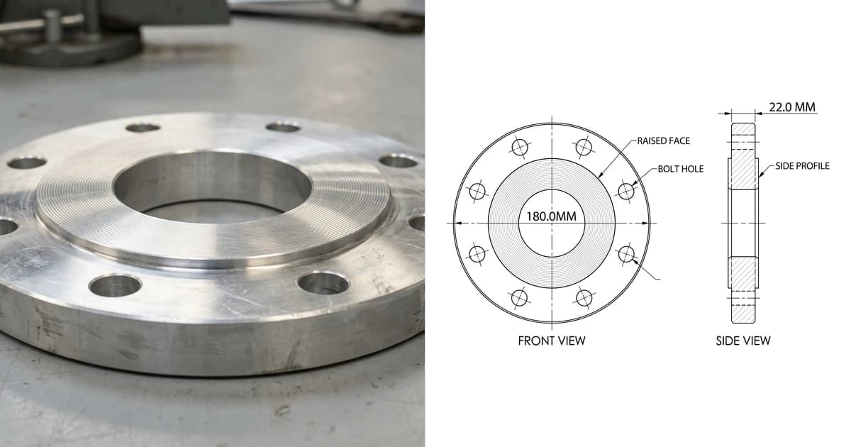
Almost everyone who sends a shop a first drawing gets the same reply, and it is not a quote. It is a list of questions. What material. What tolerance on that bore. Is that surface finished. Which of these two dimensions do you actually care about. The gap between a drawing that gets quoted and one that gets questioned is not artistic skill, and it is not software. It is a short list of information that has to be on the sheet, and this is that list.
Our articles are still written by humans!
Get human written articles in your Google feed.
The short answer
An engineering drawing is a scaled, dimensioned document that specifies how a part or an assembly must be made and how it will be checked. It shows the shape as a set of flat views, and around those views it carries everything the shape itself cannot say: how much the dimensions are allowed to vary, what the part is made from, how the surfaces are finished, and who signed it off.
That last part is what separates it from a sketch or a rendering. A drawing is a controlled document. It has a number, it has a revision, and when two people disagree about whether a part is right, the drawing is what settles it.
A specification, not a picture
The most useful way to think about the whole thing is this: a drawing does not describe the part you designed. It describes every part that would be acceptable. The bore you drew at 62 mm is not a promise that the bore will be 62 mm. It is a promise that the shop will make it close enough to 62 mm for the drawing's tolerance, and that anything inside that band gets paid for.
Once that clicks, most of the conventions stop looking arbitrary. Views exist so there is no shape the drawing could be describing other than yours. Tolerances exist so there is a defined boundary between accepted and rejected. Datums exist so two inspectors in two countries measure the part the same way round. Every rule on the sheet is there to close off an argument that would otherwise happen later, at your expense.
The seven things on every sheet
This is the checklist a shop runs, consciously or not, in the first thirty seconds of opening your file. Anything missing becomes an email. It is on this page rather than behind a download form, so you can read it now and copy the rows if you want them.
What has to be present, and what happens when it is not
Two of those deserve a warning. Units belong in the title block and nowhere else, because a drawing that mixes them is how a part comes back at 25.4 times the size you wanted. And revision matters more than people expect: the most common cause of a wrong part is not a wrong drawing, it is a right drawing at the wrong revision. If you want the longer version of this list with the acceptance criteria attached, we keep one as a manufacturing-ready checklist.
Views, and the one the part decides
The number of views is not a style choice. It is a property of the part. You need exactly as many as it takes to leave no feature ambiguous, and not one more. A flat gasket needs one. A turned shaft usually needs one plus a detail. A bent bracket needs three, because the front tells you nothing about the depth and the side tells you nothing about the hole pattern.
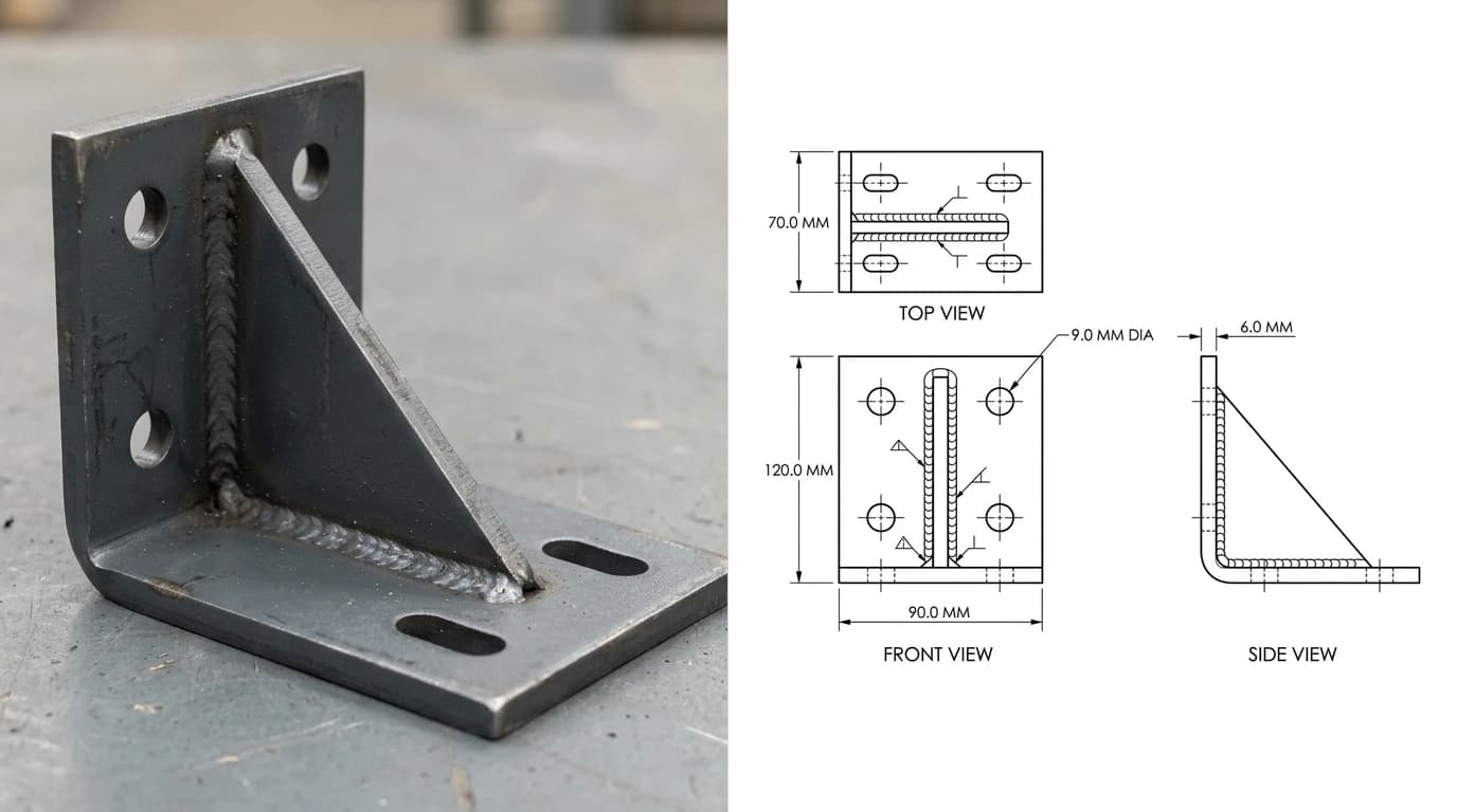
The convention that decides where those views go is projection, and it is the single most dangerous thing on a sheet to leave unstated. In third angle, used in North America, the top view sits above the front view. In first angle, used across most of Europe and Asia, it sits below. The same drawing read under the wrong convention produces a mirrored part that fits nothing, and it is entirely legible until you hold it. We wrote the whole trap up in first angle vs third angle projection.
When the outside is not enough
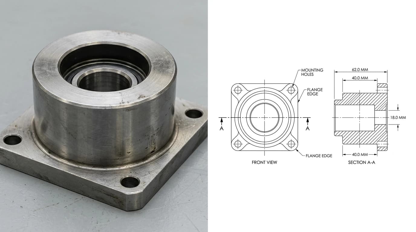
Some parts hide their real geometry inside. You can draw internal features as dashed hidden lines, and for one or two features that is fine, but a stepped bore drawn in dashed lines is unreadable. The answer is a section view: imagine cutting the part along a plane, throw away the near half, and draw what is left. The cut material gets hatched so it is obvious what is solid and what is air.
The dimension that is not a number
A dimension without a tolerance is not a specification, it is a wish. Every real dimension has a permitted band around it, and the only question is whether you stated the band or let someone else choose it for you.
Most sheets handle this in two layers. A general tolerance note covers everything that does not matter much, typically by reference to ISO 2768-m or a small table in the title block. Then the handful of dimensions that actually matter get their own tighter limits written directly on them. That split is deliberate: tolerance is the main lever on price, and tightening every dimension because you were not sure which ones mattered is the most common way to double a quote for nothing.
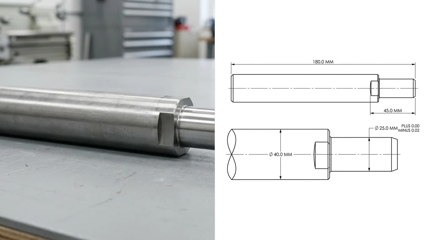
The vocabulary that goes with this is worth learning properly, because it is where drawings get genuinely technical: limits, fits, datums, and the geometric controls such as flatness, position and runout that say things a plus-or-minus number cannot. Our guides on reading tolerances and engineering drawing symbols and GD&T go through both. If you are choosing the numbers rather than reading them, the rules in how to dimension a technical drawing come first.
What the geometry cannot say
There is a category of information that no view and no dimension can carry, and it is the category people forget. A sheet metal part has to say which way it folds and what the bend radius is. A welded assembly has to say the weld type and size at each joint. A threaded hole has to say the thread designation and class, not just a diameter. A plated part has to say the coating and its thickness, and a ground face has to say how smooth, which is the job of the surface finish symbols. None of that is shape, and all of it changes the part.
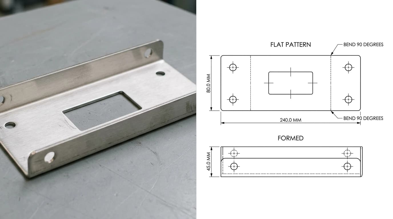
The practical rule: if a decision would change the part and it is not forced by the geometry, it belongs in a note. Machinists are very good at making what you drew. They cannot read what you meant.
Which standard yours follows
Drawings look similar the world over because they are standardised, but there are two families and they differ in ways that matter. Saying which one you followed, in the title block, costs you one line and removes a whole class of misreading.
The standards a drawing actually references, by job
Two practical notes on that table. The one that bites in real life is projection convention, because it follows the standard family: a drawing read under the wrong one produces a mirrored part. And if you are wondering whether the 2D sheet is on its way out, that is what ASME Y14.41 covers: model-based definition, where the tolerances and notes are attached to the 3D model instead of a drawing. It is real, aerospace and automotive use it, and it has not reached the average job shop. If you are sending work to one, send a drawing.
The UK sits slightly apart again with BS 8888, which wraps the ISO set into a single national standard. In practice it points at the same ISO documents, so a drawing marked BS 8888 reads as an ISO drawing.
Engineering, technical, shop or detail
These four get used interchangeably and mostly that is harmless. But they are not synonyms, and the reason they get confused is that they are not even sorted on the same axis. Two of them describe what the drawing covers, and one describes who wrote it and what it is worth contractually.
- Technical drawing is the umbrella: any scaled drawing made to communicate how something is built, mechanical or electrical or architectural or civil. Every engineering drawing is one; most technical drawings are not engineering drawings.
- Engineering drawing is the manufacturing branch of that umbrella. It carries tolerances, material and finish because something is going to be made to it. How one is prepared is governed by
ASME Y14.100in the US. - Detail drawing is a type of engineering drawing, not a different thing.
ASME Y14.24is the standard that formally defines the types, and it splits detail drawings further: a monodetail drawing covers a single part, a multidetail drawing covers several identified parts on one sheet. The others in that family are installation, layout, and the assembly drawing, which works by different rules again: it balloons parts to a list rather than dimensioning them. - Shop drawing is the odd one out, because it is a construction term defined by authorship rather than content. Under the AIA A201 general conditions, shop drawings are prepared by the contractor or a subcontractor or supplier to illustrate part of the work, and the same document is explicit that they are not contract documents. They show how the builder proposes to meet the designer's drawings; they do not replace them. We cover that, and where as-builts sit relative to both, in shop drawings vs construction drawings.
So the one-line version: technical drawing is the umbrella, engineering drawing is its manufacturing branch, detail drawing is a type of engineering drawing, and shop drawing is a contractual role. If someone asks you for a shop drawing and you send them a part drawing, you have answered a different question than the one they asked.
Four reasons a shop sends it back
These four account for most of the round trips, and all four are avoidable before you press send.
- No scale, or a scale that lies. A drawing exported at the wrong page size no longer matches its own stated scale. Dimensions govern, but a shop that spots the mismatch stops and asks rather than trusting either.
- The same feature dimensioned twice. If a chain of dimensions and an overall dimension both define the same distance, they will disagree by the tolerance, and nobody knows which one wins. Dimension it once and let the rest fall out.
- Tolerances applied by reflex. Every dimension at plus or minus 0.01 tells the shop you did not decide which ones matter, and it prices the whole part as though all of them do.
- A drawing sent without geometry, or geometry without a drawing. A PDF alone cannot be cut from; a
STEPalone carries no tolerance or finish. Send both. Which pairing goes with which process is laid out in which CAD file to send a shop.
Three ways to get one made
Which route makes sense depends on one thing: whether the part exists yet.
Draw it yourself
If the part is still an idea, it has to be modelled or drawn before it can be specified, and that means CAD. The drawing then falls out of the model as a set of projected views you dimension. This is the most control and the longest learning curve. Our roundup of free CAD programs covers where to start without paying for a seat.
Hire a draughtsman
Sensible for a one-off assembly or anything that has to carry a professional signature. You are paying for judgment as much as for drafting, and the brief matters: send photographs, measurements and the function of every critical feature, or you will pay for the same conversation twice. We compared the economics in AI vs hiring a draftsman.
Generate it from the part
When the part already exists and the files do not, which is the normal situation for a legacy component, a spare with no supplier or something a customer handed you across a counter, the fastest route is to work from the object itself. Photograph it, measure the features that matter, and let the drawing be produced from that. This is what our own generator does: it takes a photograph and returns dimensioned views exported as DXF, DWG and PDF, which you then check and correct against your own measurements before anything gets cut.
Two honest caveats about that last route, because they decide whether it is right for you. A photograph fixes proportion, not size, so the real numbers still have to come from measuring the part or from a reference object in frame. And nothing generated should go to a shop unreviewed: the tolerances, the material and the finish are engineering decisions about how the part functions, and they are still yours to make. What you save is the drafting, not the specifying.
The bottom line
An engineering drawing is not a better picture of your part. It is the document that decides what counts as correct, and everything on it exists to close a question that would otherwise be asked later. Get the seven items on the sheet, put the tolerance where it earns its cost, write down the things geometry cannot say, and state which standard you followed. Do that and the reply you get is a price, which is the only test that matters.
Frequently asked questions
What is an engineering drawing?
An engineering drawing is a scaled, dimensioned technical document that specifies exactly how a part or assembly must be manufactured and how it will be inspected. It carries the geometry as orthographic views, plus the dimensions, tolerances, material, finish and notes that the geometry alone cannot express. Unlike a sketch or a render, it is a controlled document: it is what a shop quotes against and what an inspector measures against.
What is the difference between an engineering drawing and a technical drawing?
Technical drawing is the broad term for any scaled drawing made to communicate how something is built, including architectural and civil work. An engineering drawing is the subset used for manufactured parts and assemblies, so it carries manufacturing information such as tolerances, surface finish, material and thread callouts. In everyday shop use the two terms are often swapped freely.
What must be included on an engineering drawing?
Seven things: enough orthographic views to describe the shape without ambiguity, the projection convention used, dimensions that locate every feature once, tolerances on the dimensions that matter, the material and its condition, the surface finish and any treatment, and a title block carrying the part number, revision, scale, units and who approved it. If any one of those is missing, someone has to ask a question before they can quote.
What is a leader line in an engineering drawing?
A leader line is a thin line with an arrowhead at one end that points at a feature and carries a note or a dimension at the other end. It is used when the callout will not fit next to the feature itself, for example a hole diameter, a thread specification, a weld symbol or a surface finish requirement. The arrowhead touches the feature it describes, and the text sits on a short horizontal shoulder at the far end.
What is a datum in an engineering drawing?
A datum is a reference feature that other dimensions and geometric tolerances are measured from. It fixes where the inspector puts the part down and where they zero their instrument, so the same drawing measures the same way in two different shops. Datums are labelled with a letter in a box, usually A, B and C, and are chosen for how the part actually functions rather than for drawing convenience.
What is plan view in an engineering drawing?
The plan view is the view looking straight down on the part from above, showing its footprint. In mechanical drawings it is more often called the top view; plan is the term used in construction and civil drawings. It appears directly above or below the front view depending on whether the drawing uses first angle or third angle projection.
Do I still need an engineering drawing if I have a 3D model?
For most machined and fabricated work, yes. A STEP or IGES model carries the exact shape but not the tolerances, surface finish, material condition, thread class, weld sizes or inspection requirements. Shops quote and inspect against the drawing and cut against the model, which is why the usual hand-off is both files together rather than either one alone. The alternative is model-based definition, covered by ASME Y14.41, where tolerances and notes are attached to the 3D model itself. It is established in aerospace and automotive but is still uncommon at a general job shop.
What are the types of engineering drawing?
ASME Y14.24 defines the types formally. The main ones are the detail drawing, which fully documents a part, the assembly drawing, which shows how parts go together, the installation drawing, which shows how the item is fitted in place, and the layout drawing, which carries design development information rather than a final specification. Detail drawings split further into monodetail, covering one part, and multidetail, covering several identified parts on one sheet.
Can you make an engineering drawing from a photo?
Yes, and it is the normal route when the part exists but the original files do not, such as a legacy component or a spare with no supplier. The photograph fixes the shape and proportions, and the real dimensions come from measuring the part with calipers, or from a known reference object placed in the frame. Software then produces the dimensioned views and exports them as DXF, DWG or PDF.
Sources
- ASME Y14.100-2017: Engineering Drawing Practices, the master US standard for how a drawing is prepared
- ASME Y14.24-2020: Types and Applications of Engineering Drawings, which defines detail, assembly, installation and layout drawings
- ASME Y14.5-2018: Dimensioning and Tolerancing, the US GD&T standard
- ISO 128-1:2020: Technical product documentation, general principles of representation
- ISO 129-1:2018: Presentation of dimensions and tolerances, general principles
- ISO 1101:2012: Geometrical product specifications, geometrical tolerancing
- ISO 7200:2004: Technical product documentation, data fields in title blocks
- ISO 2768-1:1989: General tolerances for linear and angular dimensions
- AIA A201-2017: General Conditions of the Contract for Construction, which defines shop drawings at section 3.12