You finished the design, you found a shop, and now a dialog box is asking what format to export. Pick wrong and the best case is a reply asking for a different file, the worst case is a quote based on a misread of your part. The choice is simpler than the long list of extensions makes it look, once you know the one question that splits them all.
First split: are you sending a shape or a drawing?
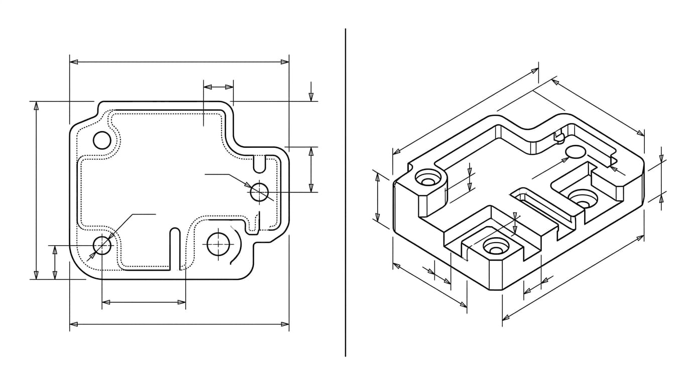
Every format below falls into one of two jobs. Some carry the geometry of the part, the actual 3D shape or 2D profile a machine will follow. Others carry the drawing, the human-readable sheet with dimensions, tolerances, threads and notes, written in a standard set of engineering drawing symbols. They are not interchangeable, and the most common file mistake is sending one when the shop needs the other.
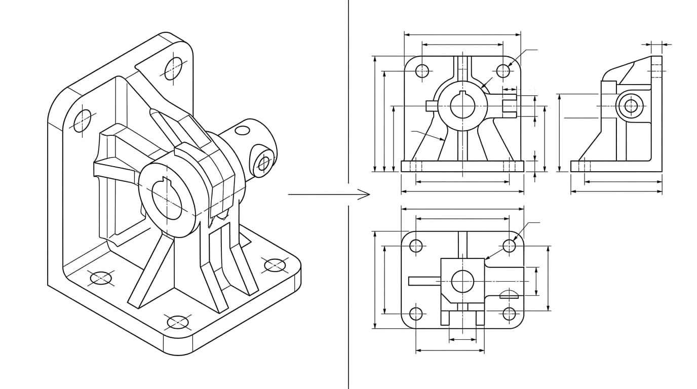
Geometry tells the machine what shape to cut. The drawing tells it how good the result has to be. For anything beyond a simple flat part, a shop needs both, which is the reason 2D drawings have not disappeared in a 3D world. We dug into exactly why in why machine shops still want 2D drawings.
The five formats you will actually meet
- DXF (Drawing Exchange Format). A 2D format that stores flat geometry as lines, arcs and splines. It is the standard for flat-profile cutting and was designed from the start to move between different programs. To make one from an image, use our free image to DXF converter, or compare the options in the best JPG to DXF converters. To take a DXF the other way — into a 3D model — see our CAD workflow guides.
- DWG.AutoCAD's native 2D format. It is everywhere, but it is proprietary and tied to AutoCAD versions, so it can open imperfectly in other software. Fine to keep, riskier to send — we compare the pair in DWG vs DXF.
- STEP (.step or .stp). The ISO standard for sharing exact 3D geometry. It stores true mathematical surfaces, which is what CAM software needs, and it opens in essentially every CAD and manufacturing tool. This is the gold standard for 3D interchange.
- STL. Describes a surface as a mesh of triangles. That is perfect for 3D printing and useless for precision CNC, because a mesh only approximates curves and throws away the exact geometry.
- PDF. The universal way to share the drawing: dimensions, tolerances, finish and notes that a person reads. CAM software cannot machine from it, so it accompanies a geometry file rather than replacing one. If a PDF is all you have and you need geometry out of it, see how to convert a PDF drawing to DXF, and for the head-to-head on when to send a viewable PDF versus an editable DWG, see PDF vs DWG.
Side by side, the differences are easy to see:
DXF vs DWG vs STEP vs STL vs PDF at a glance
| Format | 2D / 3D | What it carries | Best for | Send to a shop? |
|---|---|---|---|---|
DXF | 2D | Flat lines, arcs and splines | Laser, plasma, waterjet, sheet metal | Yes — the portable flat-cut file |
DWG | 2D | The same as DXF, but AutoCAD-native | Editing inside AutoCAD | Prefer DXF instead |
STEP | 3D | Exact surfaces and solids | CNC machining, 3D interchange | Yes — the 3D standard |
STL | 3D | A triangle mesh (approximate) | 3D printing | Only for printing |
PDF | 2D | Dimensions, tolerances and notes — no geometry | The human-readable spec | Yes — always with a geometry file |
Which format by process
Match the file to what the machine actually does:
What to send for each manufacturing process
| Process | Geometry file | Plus the drawing |
|---|---|---|
| Laser, plasma, waterjet (flat) | DXF | PDF if there are tolerances or finishes |
| CNC milling and turning (3D) | STEP | PDF drawing, almost always required |
| Sheet metal (cut and bend) | DXF flat pattern, often a STEP too | PDF with bend and finish notes |
| 3D printing | STL | STEP if the printer accepts it |
The pattern is consistent. Flat work runs on DXF. Solid 3D work runs on STEP. 3D printing runs on STL. And in every case where the result has to hit a tolerance, a PDF drawing rides along to state it. If your job is flat profile cutting, the DXF still has to be laser-ready: see how to prepare a DXF for laser cutting, and if it imports at the wrong scale, why a DXF imports at the wrong size.
Three mistakes that cost a quote
- Sending only a PDF for a machined part. The shop cannot pull exact geometry from a PDF, so they either ask for a STEP or trace it by hand and bill you for the time. Pair the PDF with a geometry file.
- Sending an STL to a CNC shop. The mesh approximates curves, so the machined part inherits the faceting. For CNC, send STEP. Keep STL for the 3D printer.
- Sending a DWG and assuming it opens cleanly. Version mismatches and proprietary quirks mean your DWG may not look the same on the other end. Export a DXF for sharing and your odds improve a lot.
Why experienced people send two files
The habit that prevents nearly all of this is simple: send a geometry file and a drawing together. For a 3D part that is a STEP plus a PDF. For a flat part it is a DXF plus a PDF. The geometry lets the machine cut the shape, and the drawing tells it the tolerances, threads, material and finish that the geometry cannot carry.
That drawing is not paperwork for its own sake. It is the document the shop quotes against and the inspector measures against. A clean, correctly dimensioned PDF, exported to DXF where the process needs it, is exactly the output a tool like TechDraw AI is built to produce. If you want to be sure that sheet is complete before you send it, run it through our manufacturing-ready checklist.
The bottom line
Forget the alphabet soup and remember the logic. Decide whether you are sending shape or a drawing. Match the geometry file to the process: DXF for flat, STEP for 3D, STL for printing. Then send the PDF drawing alongside it so the shop knows not just what to make, but how good it has to be. Do that and your file will quote on the first try instead of the third.
Frequently asked questions
What is the best file format to send to a CNC machine shop?
For 3D machined parts, send a STEP file plus a PDF drawing. STEP carries the exact geometry the shop's CAM software needs, and the PDF carries the tolerances, threads, finish and notes that the geometry cannot express. STEP is the most widely accepted exchange format for CNC machining.
What file format do I need for laser cutting?
DXF. Laser, plasma and waterjet cutting are 2D profile operations, and DXF is the standard format for flat cutting paths. Many shops also accept DWG, but DXF is the more portable choice across different machines and software.
Can a machine shop work from a PDF alone?
Usually not for machining. A PDF is for human eyes: it shows dimensions, tolerances and notes, but CAM software cannot read exact geometry from it. Send a PDF as the drawing and pair it with a STEP file for 3D parts or a DXF for flat parts.
Why is STL not good for CNC machining?
STL describes a surface as a mesh of triangles, which is only an approximation of the real shape. CAM software for CNC needs exact mathematical curves and surfaces, which STL does not store. STL is the standard for 3D printing, not for CNC machining.
Should I send DWG or DXF?
Prefer DXF for sharing. DWG is AutoCAD's proprietary native format and can cause version and compatibility issues between different programs. DXF was created as an exchange format and opens reliably in far more software, which is why it is the safer file to send.