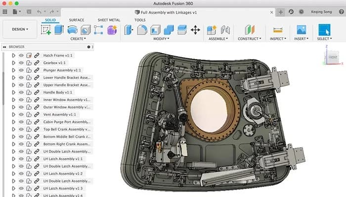
 Autodesk Fusion 360
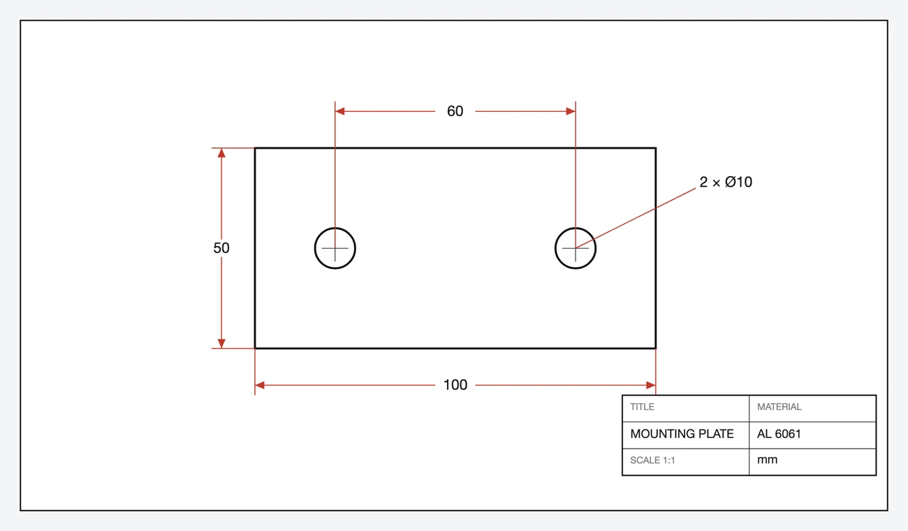
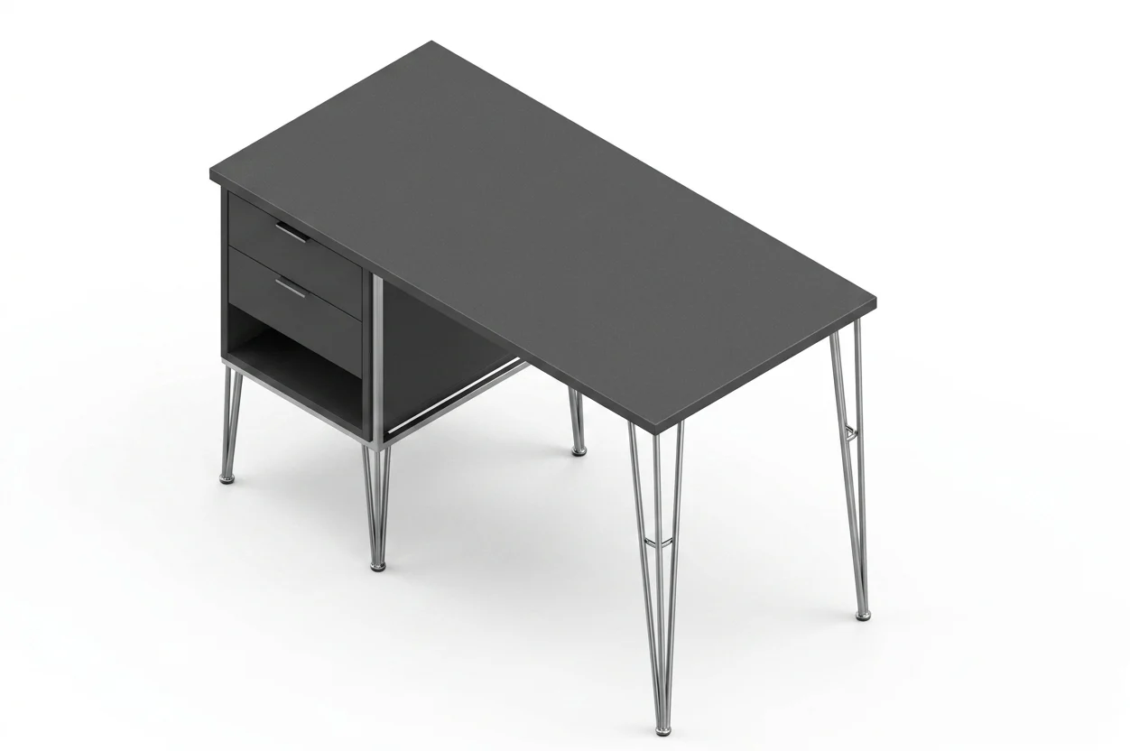
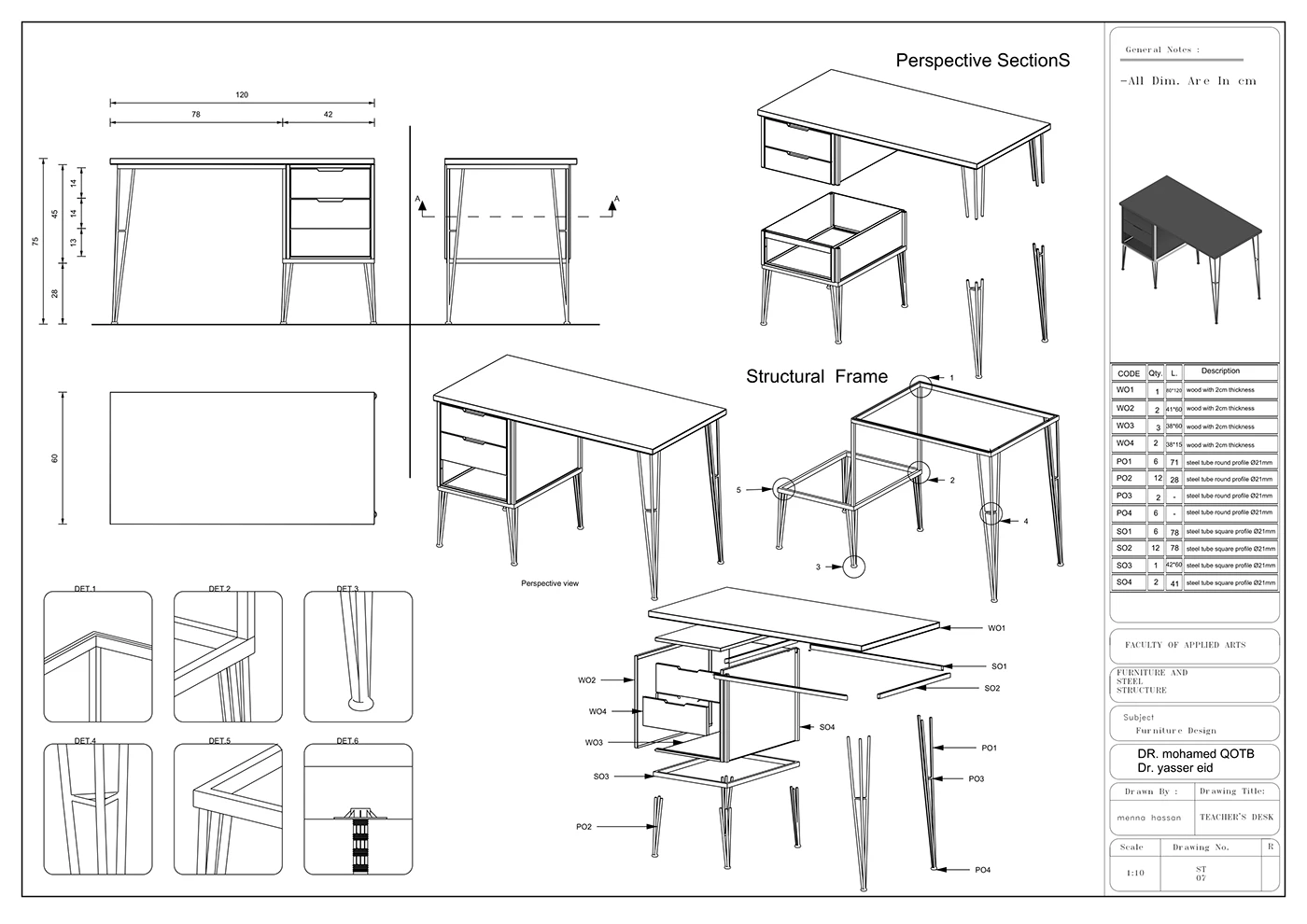
Photograph a discontinued part, get the DXF, revolve or extrude it in Fusion, then redesign or run CAM. No original drawing needed.
A part fails on site, someone snaps a photo, and an engineer has a 3D model to modify the same afternoon.
For laser, waterjet or router work the DXF often goes straight to CAM; Fusion just nests and toolpaths it.
Generate a first 2D concept from a text description, import it, and pressure-test the geometry in Fusion before committing.
Who does what
Division of labour, not redundancy. Each tool owns the half of the job it's actually good at.
| Step in the job | TechDraw AI | Fusion 360 |
|---|---|---|
| Capture from a photo | ✓ | ✗ |
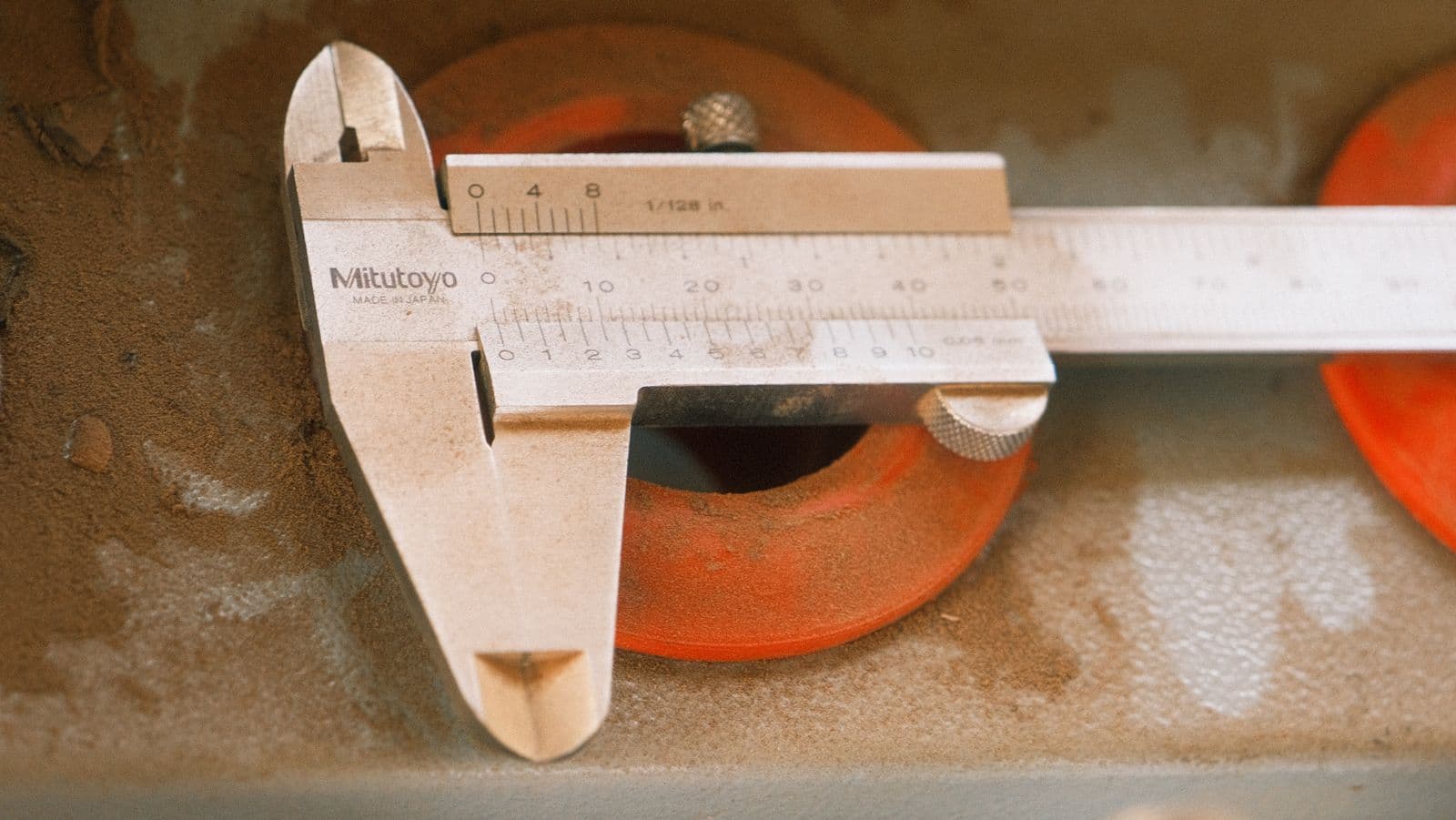
| Real measured dimensions | ✓ | ~ |
| Dimensioned 2D drawing | ✓ | ~ |
| DXF / DWG export | ✓ | ✓ |
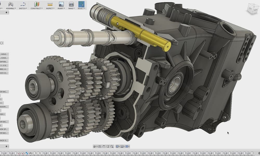
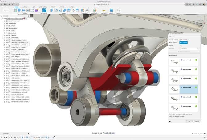
| Parametric 3D body | ✗ | ✓ |
| Assemblies & motion | ✗ | ✓ |
| CAM toolpaths & simulation | ✗ | ✓ |
| Best at | Photo → drawing | Drawing → 3D |
See it for yourself
Drop in a photo of a part. You'll get a dimensioned drawing and a clean DXF, ready for Fusion. No account needed to start.
The five-step handoff
Once you've exported the drawing from TechDraw AI as a DXF, the import into Fusion is short. If your part is flat, like a gasket, bracket or laser plate, the DXF is the production file and you can stop after step 2.
The seam is a DXF. Mind your units, layers and closed loopsand it's a seam you barely notice. Geometry in, parametric body out.
Extrude vs. revolve
The DXF is always a flat 2D profile. How you give it depth depends on the part.
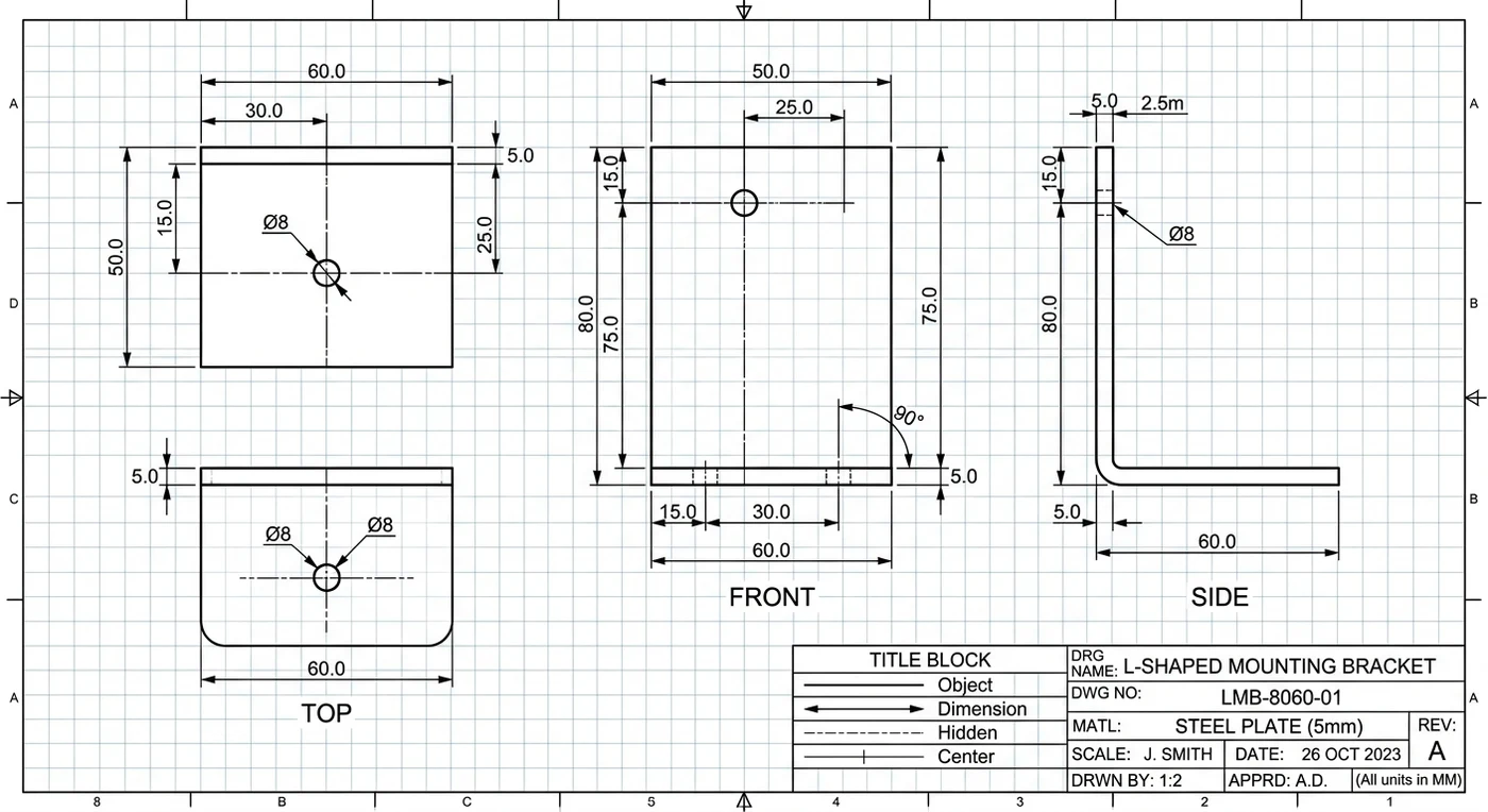
- Brackets, plates, housings, constant cross-section
- Select the closed profile, extrude to thickness
- Closed cut-outs become pockets in the same op
- Import settings can even auto-extrude to a thickness
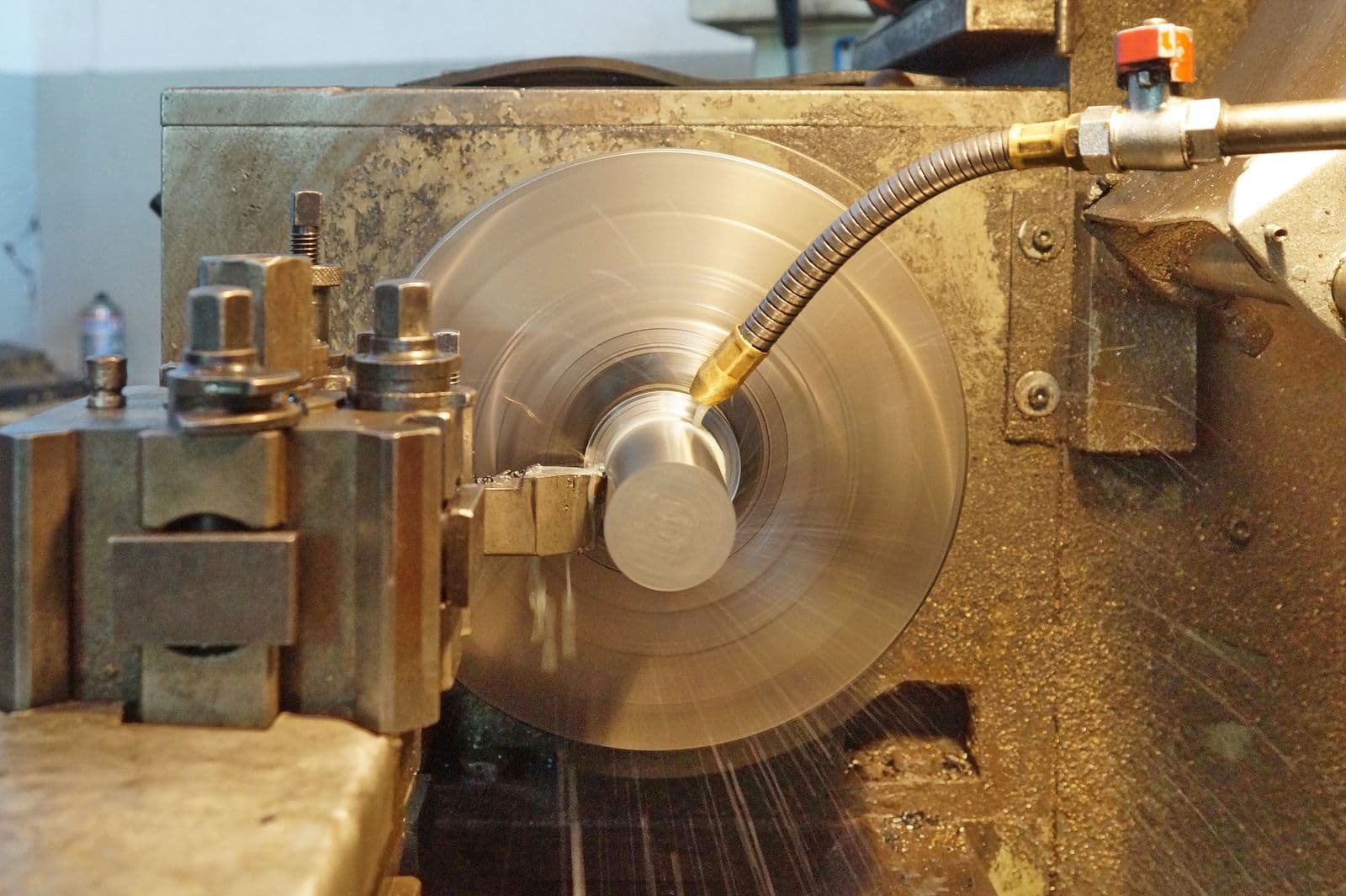
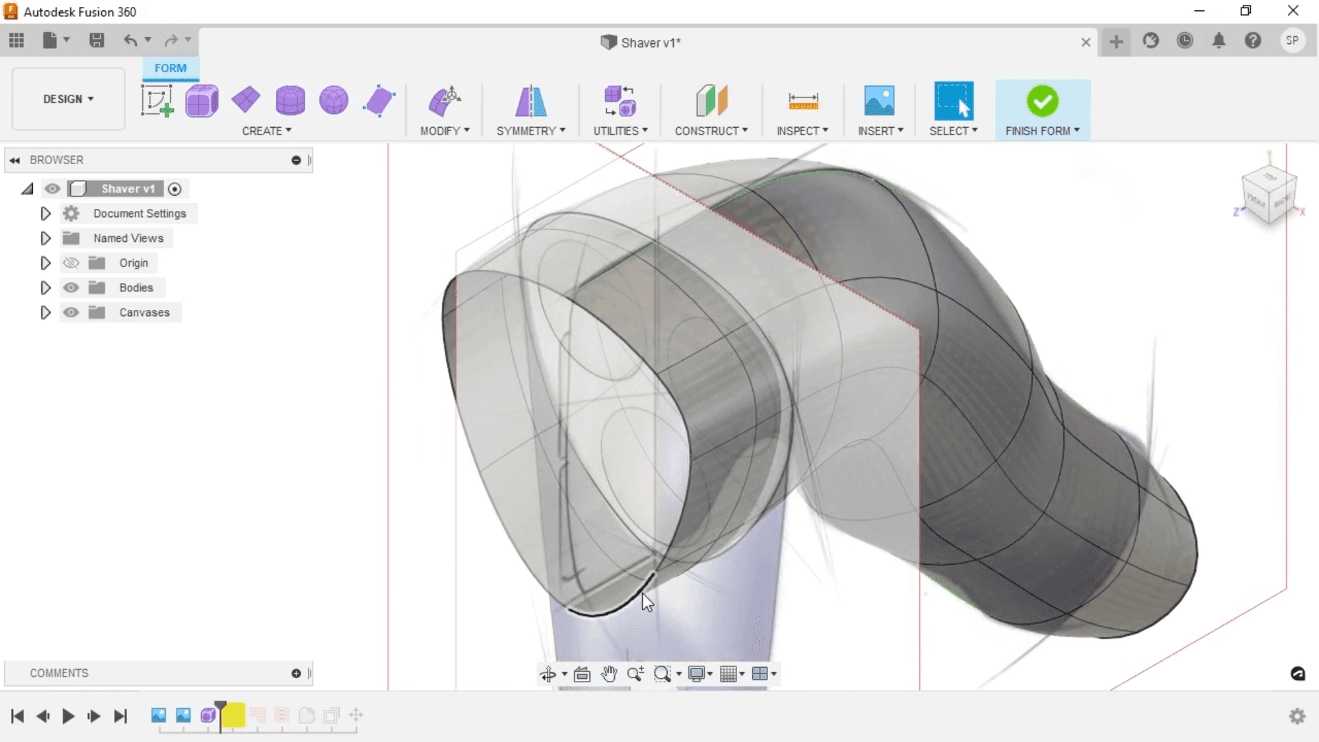
- Shafts, bushings, pulleys, anything round
- Export the half-section profile
- Add a centerline as the axis, revolve 360°
- Fusion has a dedicated DXF-for-turning workflow
Three gotchas that break the import
Almost every “my DXF won't extrude” thread comes down to one of these. Knowing them up front saves the ten minutes.
Cleanest habit: from TechDraw AI, export one DXF of just the profile geometry for modelling, and keep the full dimensioned drawing (or a PDF) open beside Fusion as your spec. The model gets clean lines; you keep the numbers in view.
Where this combo earns its keep
| Job | TechDraw AI | Fusion 360 |
|---|---|---|
| Capture an undocumented part | ||
| Dimension it to real size | ||
| Build the 3D body | ||
| Redesign / modify | ||
| Run CAM / cut it |
Start at the part, end at the 3D model
Generate the dimensioned DXF in minutes, then take it into Fusion. No tracing, no blank canvas. Free to start, no account needed.
Frequently asked questions
Does TechDraw AI replace Fusion 360?
Not at all. They solve different halves of the job. TechDraw AI gets you from a physical part or an idea to a dimensioned 2D drawing and a clean DXF in minutes. Fusion 360 is where that DXF becomes a parametric 3D model, an assembly, a CAM toolpath or a simulation.
How do I get a TechDraw AI drawing into Fusion 360?
Export the drawing as DXF from TechDraw AI, then in Fusion choose Insert › Insert DXF, pick the file, and select the plane to place it on. Fusion brings the geometry in as a sketch you can extrude, revolve or use as a CAM profile.
Why won't my imported DXF extrude in Fusion?
Extrude needs a closed profile. If the region doesn't shade blue when you hover it, there's a gap somewhere. Zoom in, find the open vertices, and close them with a coincident constraint or a trim. A clean export from TechDraw AI is already closed.
Do I lose the dimensions when I import the DXF?
The dimension text comes in on its own DXF layer as annotation, not as live constraints, and that holds for any DXF in any CAD package. Keep that layer for reference and re-apply the dimensions you care about as Fusion sketch constraints.
Does this work for turned (round) parts too?
Yes. For a shaft, bushing or any part with an axis of revolution, import the DXF profile, keep just the half-section, add a centerline, and use Revolve instead of Extrude.