Sheet Metal Drawings& Flat Patterns with AI




1,200+ reviews
Sheet Metal Drawings in three steps
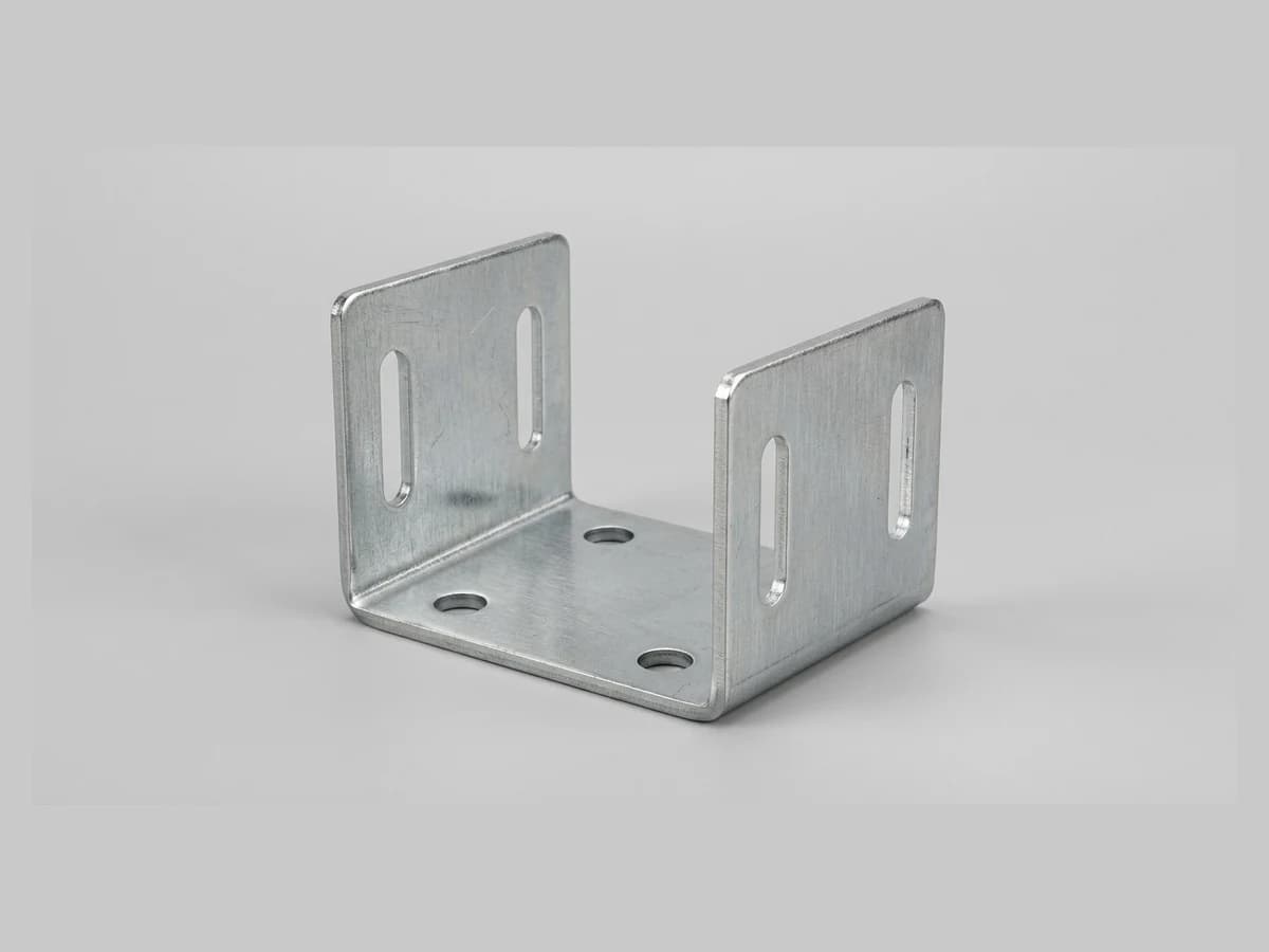
Photograph the part
Shoot the bent bracket, panel or enclosure you need documented, or the flat blank you want to reproduce. Clean edges photograph best.
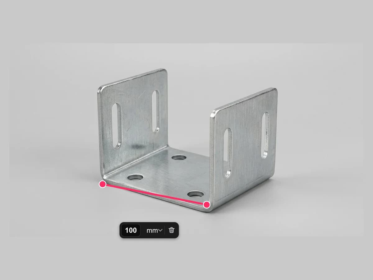
Set the real size
Choose the drawing type and units, then anchor the scale with one measured dimension and the material thickness so the sheet reads true.
Get drawing and flat pattern
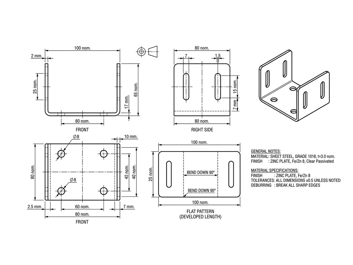
Receive a dimensioned drawing with views, bend lines and a labelled flat pattern, and export the cutting geometry as DXF for the laser, plasma or punch.
From bent part to cut-ready geometry
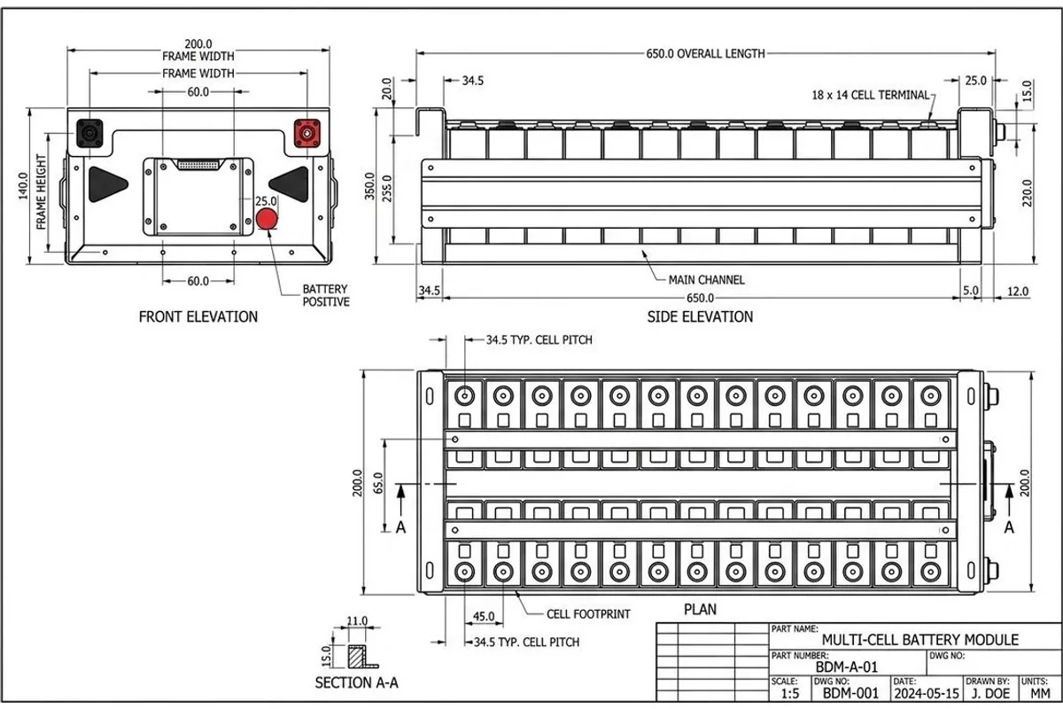
Sheet metal lives in two states at once: the bent part the customer sees and the flat blank the laser cuts. A proper drawing carries both, formed views with bend lines and a dimensioned flat pattern. TechDraw AI drafts that sheet from a photo, anchored to your measured size and thickness, so a bracket someone hands you at the counter becomes a documented, quotable part in minutes.
One honest note: developed lengths depend on your bend allowance, and that depends on your tooling and material. Treat the generated flat pattern as the drafted starting point and confirm the K-factor against your press brake's numbers before cutting a batch. The DXF export goes straight into your nesting software either way.
Fabrications and their flat patterns
Twenty formed parts and the drawing drafted from each photo, bend lines and developed length included. Open one to drag the photo across the sheet.
Fab shops in 40+ countries document their parts with AI.

“My shop foreman asked which drafter made these sheets. It was just me and TechDraw AI lol. Did 3 parts in one afternoon.”

“found a tolerance error my old drawings missed for years. The AI flagged it and fixed the callout automatically.”
“I use this for client handovers now. Upload a part, get fully dimensioned views in 10 minutes. They think I have a whole drafting team.”

“Just started at a furniture workshop and had no idea how to do a cutting list. This generated the whole BOM from one photo. Way faster than I expected.”
“Tested every projection angle in 5 min. love it.”

“pretty impressed honestly. Full orthographic set in under a minute and the dimensioning was spot on.”

“I used to redraw everything by hand. Now I sketch on paper, photograph it, and get clean editable geometry back. Saved me hundredss of hours already.”
“found the GD&T symbols it placed were textbook correct. Nice.”

“Drew up my whole assembly in one evening. Showed my boss and he tought I outsourced it. Nope, just AI.”
“I'm not a draftsman at all but this made me feel like one. Tried an exploded view for a bracket and actualy sent it to the machine shop.”

“Only tool where the title block and standards come out ISO-correct every time. Huge diffrence compared to others.”
“used it to document my dad's workshop jigs. He saw the sheets and was like okay do all of them lol.”

“Been using it for 3 months on a product line. The AI keeps every view and the BOM in sync when I change a dimension. Saved me probably 2000+ hours of rework.”

“genuinely fun to use. The auto-dimensioning is addicting.”
“This replaced my drafting board, my templates, and half my CAD busywork. Not even exagerating.”

“section views that used to take an hour now take seconds. Worth every penny.”
“Changed one hole diameter and it updated across all four views and the parts list instantly. Mind blown.”

“Does in seconds what took me hours in CAD. Clean lines, correct scale. No lerning curve at all.”
“On the free plan and its been enough for my prototyping. Already exported 3 drawings to DXF. Will upgrade when the project scales.”

“Boss approved the drawing on the first pass wich never happens lol. Sent it to production same day.”

“Was redrawing a frame for weeks. Fed the photo into TechDraw and had the full set inmediately. Should have done this first.”

“used it for a tender submission and won the job. Big time saver.”

“upload a render, pick the views, export the sheet. 20 minutes total.”
“Tried 4 or 5 CAD tools before this. The line quality here is noticably better and it actually places dimensions correctly wich none of the others did. Game changer.”

“quick, easy, accurate. Using it for all my fabrication drawings now.”
“My colleagues kept asking who drafted my sheets. Told them it was AI and half the team signed up the same week haha.”
“As a mechanical engineer I was skeptical but this speeds up my workflow so much. Clients get drawings AND a parts list right away.”

“Where was this when I documented my first machine?? Now I run everything through the AI first and export production-ready sheets.”
Frequently asked questions
Can AI make a sheet metal drawing from a photo?+−
Yes. Photograph the bent part, set one measured dimension and the material thickness, and TechDraw AI drafts a dimensioned drawing with formed views, bend lines and a labelled flat pattern, in the conventions a fab shop expects.
Can I get a flat pattern from a photo of a bent part?+−
Yes. The drawing includes an unfolded flat pattern view with bend lines shown as chain lines. Developed lengths depend on bend allowance, which varies with your tooling and material, so confirm the K-factor against your press brake before cutting a production batch.
Can the DXF go straight to a laser or plasma cutter?+−
Yes. Export the cutting geometry as DXF and import it into your nesting or CAM software like any other cut file. Closed contours and real-world scale are exactly what laser, plasma and waterjet tables need, and both are checked before export.
Does it handle bend allowances and K-factors?+−
The flat pattern is drafted with standard assumptions, and honest advice is to treat it as a starting point: bend deduction is a property of your specific press brake, dies and material. Verify the developed length on the first article before running the batch, as you would with any new flat pattern.
What if I only have the flat blank, not the bent part?+−
That works too, and it is simpler: photograph the flat part, anchor the scale, and export the traced geometry as a dimensioned drawing or a DXF. For quick outline tracing of clean flat parts, the free in-browser image to DXF converter handles it without a signup.
What formats does it export for fabrication?+−
DXF for the cutting table and CAM, DWG for CAD, PDF for quotes and the shop floor, SVG for laser workflows. One drawing exports to all of them.
Same engine, a different rulebook
A flat pattern and a furniture cut list are the same job under different rules: read the object, work out the sizes, write the sheet the next machine can act on. These are the other rulebooks it knows.
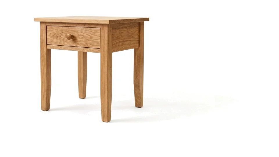
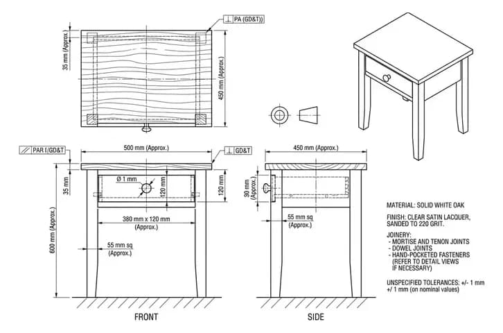
Furniture
Shop drawings with joinery detail, real sizes and a cut list.
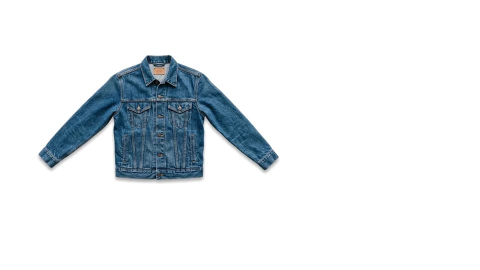
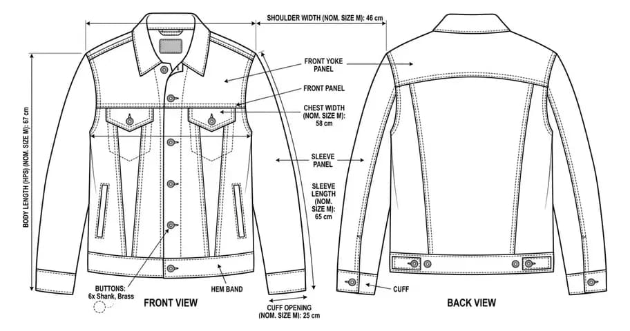
Clothes & Fashion
Front and back flats with the callouts a tech pack needs.
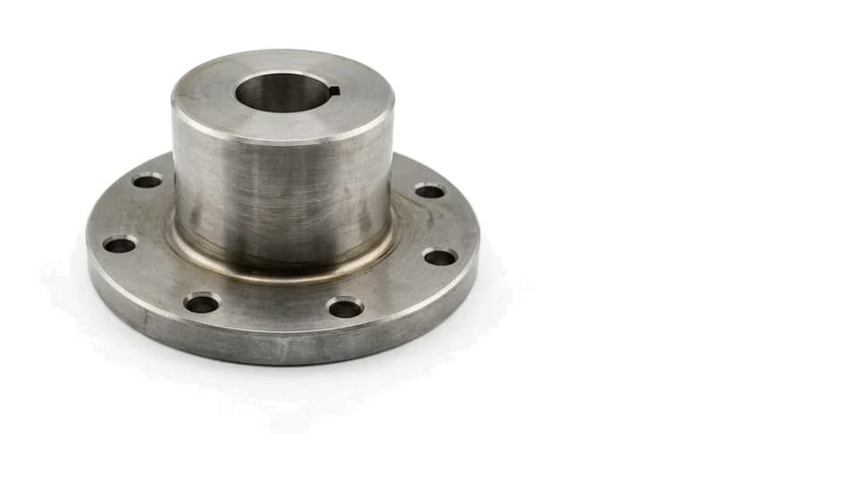
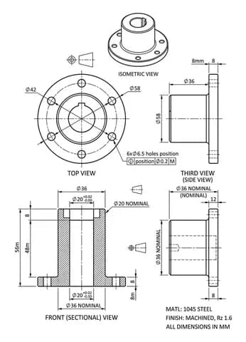
Machine Parts
Views, tolerances and a DXF your machine shop can quote from.
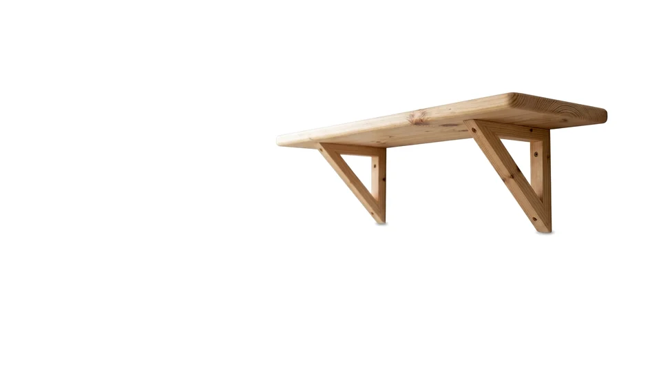
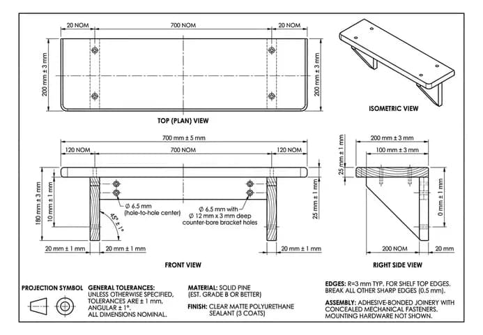
Woodworking
Plans you can build from, or a 1:1 template to print.
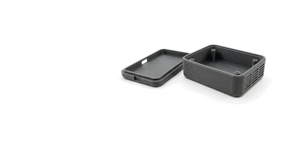
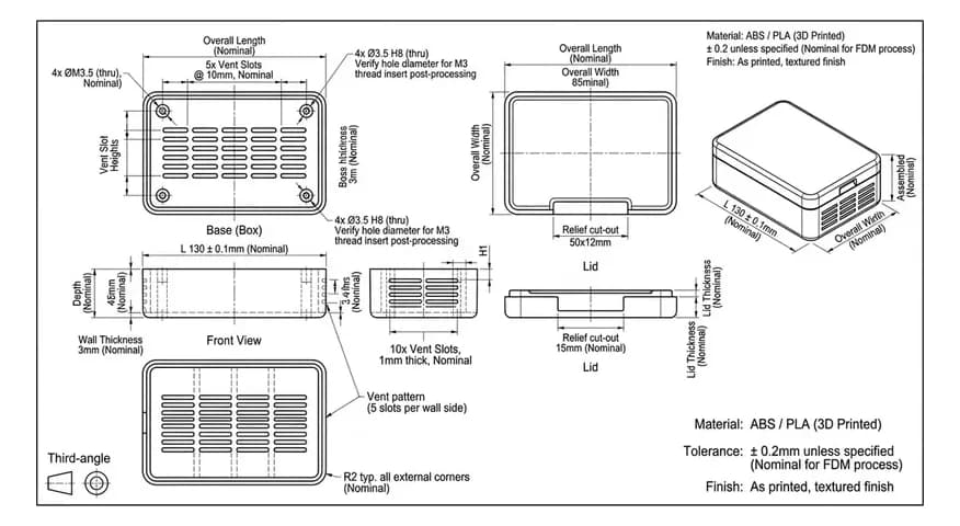
3D Printing
Wall thickness, clearances and fits, checked before you print.
Or start somewhere else. Describe the part in words and get the sheet or a 3D model without a photo, or get the object back as a 3D model from a photograph of it or from the drawing you already have.
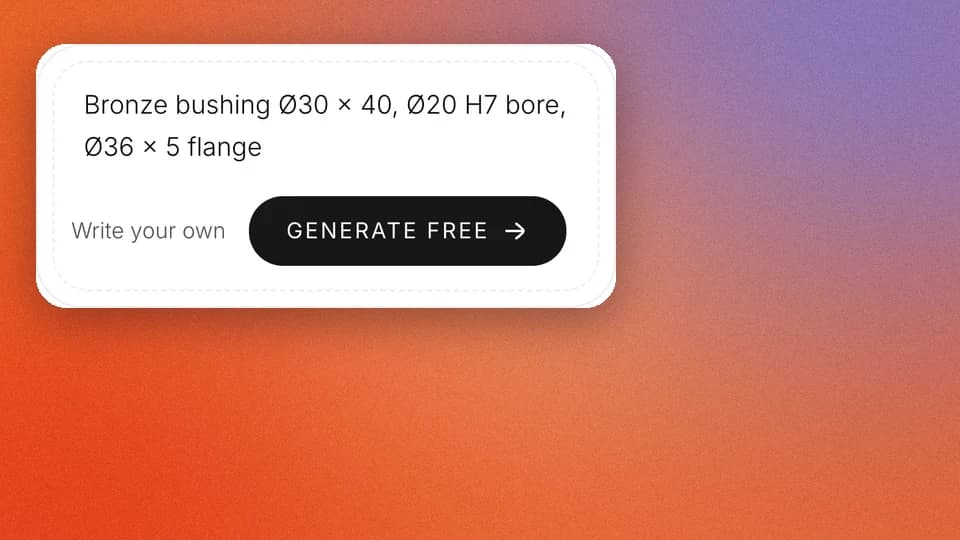
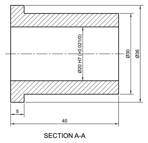
Text to drawing
Describe the part in a sentence. The sheet is computed from your numbers.
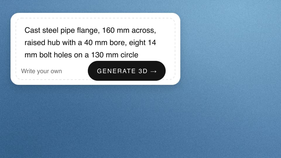
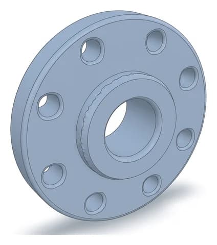
Text to 3D CAD model
Describe the part in a sentence and get it back as a 3D model.
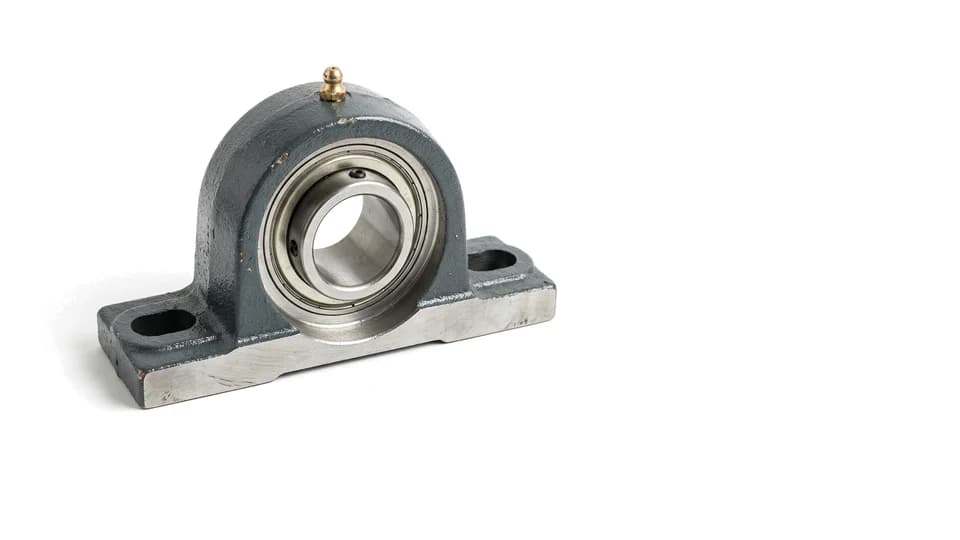
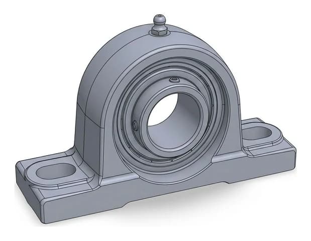
Photo to 3D CAD model
A photograph of the real thing, reconstructed as a mesh you can print.
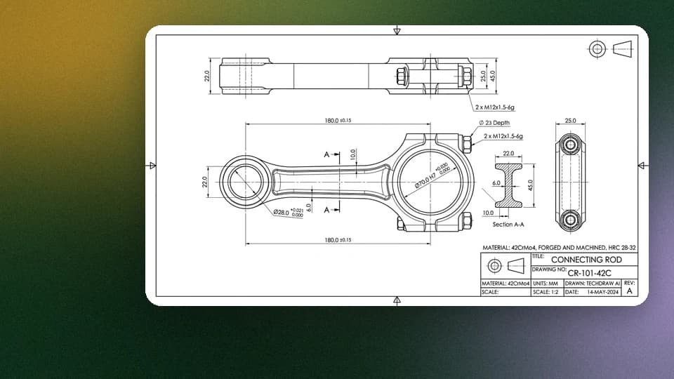
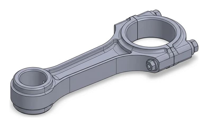
Drawing to 3D CAD model
A DWG, a DXF or a picture of the sheet, rebuilt as a 3D model.