A CNC plasma table does not read your drawing the way you do. It drives a torch along a path, contour by contour, exactly as the file lays them out. So a DXF that looks right on screen can still cut badly: an open outline the torch never closes, a part scaled to a fraction of its size, or a pierce mark sitting on a finished edge. Getting a clean plasma cut is mostly about handing your CAM software a clean DXF, and if you are starting from a photo or a sketch instead of CAD, the rules are refreshingly simple.
What plasma actually wants from a DXF
Plasma cutting is a 2D profile operation, the same family as laser and waterjet: the machine drags a cutting head along a flat sheet of conductive metal and the arc blows through it. It does not care what the part looks like rendered, it only follows vector paths, lines, arcs and polylines. A DXF is the standard way to carry exactly that, which is why every plasma CAM tool opens one. Keep the file to the cut geometry and nothing else:
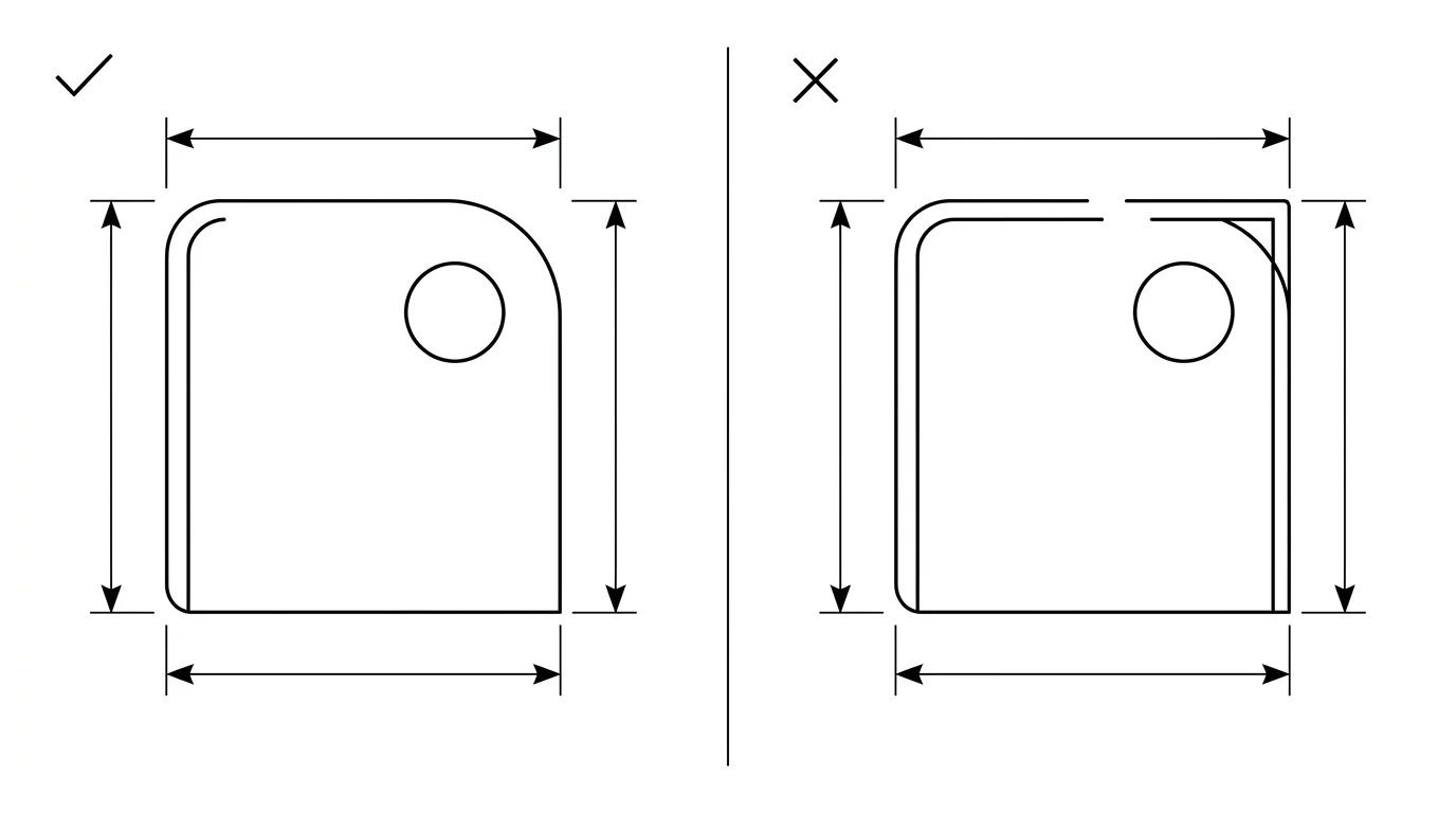
- Every contour is a closed loop. The outer profile and every interior cutout must start and end at the same point. A closed loop tells the CAM software which side is the part and which is scrap, which is what lets it offset the torch for kerf and drop a pierce into the waste. An open path, two endpoints sitting a hair apart, gets read as a stray line and the torch stops, reroutes, or cuts a slit instead of a shape.
- Outline only. Strip dimensions, hatching or fill, construction lines, the title block and any text. None of it is a cut path, and leftover geometry becomes stray pierces in the middle of your sheet.
- Simple entities. Lines, arcs and lightweight polylines import most reliably. Many plasma CAMs choke on splines, so convert curves to polylines or arcs before exporting.
- Units locked to millimetres. A DXF stores plain numbers; the unit is decided on import. Set it explicitly so the part does not arrive 25.4 times too small.
If that list sounds familiar, it is the same discipline behind a laser-ready file. Plasma is more forgiving on fine detail and far less forgiving on heat, but the file rules overlap almost completely, so our guide to preparing a DXF for laser cutting is a good companion read. What changes for plasma is everything downstream of the file, the kerf, the pierce and the torch height, which we get to below.
From a photo or sketch to a plasma DXF
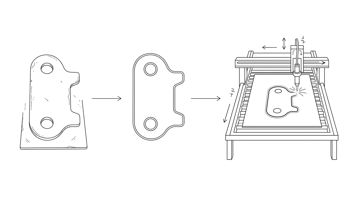
Most plasma work is flat steel you can photograph: a bracket, a gusset plate, a sign, a mounting plate, a gear blank. You do not need to model it in CAD to cut it. You need its outline as vectors at the right size. That is a tracing problem plus a scaling problem, and a photo solves the first while you solve the second.
Here is the honest version of how it works, because the size step is where people get burned. A camera flattens the world and throws away distance, so a 40 mm part up close and a 400 mm part far away can land identical pixels. A bare photo gives you proportions, never millimetres. To turn the trace into a part you can actually cut, you feed in one known length, a tape across the plate, a caliper on one edge, and everything else scales from it. The full reasoning, and how accurate it is, lives in how to get dimensions from a photo.
- Shoot the part square-on. Lay the flat part down, hold the camera at 90° centred over it, fill the frame, and light it evenly so the outline is crisp. Shooting at an angle bends straight edges and scales the part wrong.
- Trace the outline into vectors. Our free image to DXF converter does this in your browser: drop in the photo or a high-contrast sketch, tune the trace, and it gives you closed DXF polylines. It works best on flat line art and clean silhouettes, which is exactly the kind of part plasma cuts.
- Set the real size with one measurement. Anchor the drawing to a single known dimension so the whole outline locks to true scale. This is the step a photo physically cannot do for you, and it is the difference between a cuttable file and a scrap sheet.
- Clean and export the DXF. Close any tiny gaps in the trace, drop duplicate lines, and export in millimetres ready for CAM.
If the trace comes back rough, jagged arcs or stair-stepped curves that would cut ugly, see fixing a jagged vector trace before you commit the sheet. And if you want to compare the tracing tools out there, we ranked the best JPG to DXF converters. For folded steel where the flat pattern matters more than the photo, sheet metal drawings from a photo covers the bend allowance side that a plain plasma profile ignores.
Kerf, lead-ins and pierce points live in CAM, not the DXF
This is the single biggest difference from drawing for a printer, and the thing that trips up people coming from graphic design. Your DXF holds the nominal finished outline. Everything about how the torch actually negotiates that outline is set later, in CAM. Do not try to draw any of it into the file.
- Kerf. The plasma arc has real width and removes a band of metal as it travels, the kerf, typically around
0.8to1.5 mmdepending on amperage, thickness and consumables, much wider than a laser. You draw the part at true size and the CAM software offsets the torch path by half the kerf, inside or outside, so the finished part comes out on dimension. Each material and consumable combo has its own measured kerf value you enter once in CAM. - Lead-in and lead-out. The torch blows a wider hole when it first pierces than it does while running. A lead-in starts that pierce out in the scrap and walks the torch onto the line, so the pierce dimple never lands on the finished edge; the lead-out walks it off again. CAM places these automatically, sized to the material. They are never part of the DXF.
- Pierce points and order. Where the torch pierces, which interior holes cut before the outline, and how parts are nested on the sheet are all CAM decisions. A clean closed outline is what lets the software make them well.
One more plasma-specific piece that has nothing to do with your file but everything to do with the cut: torch height control (THC). Steel warps as it heats and no sheet is perfectly flat, so the THC watches the arc voltage and drives the Z-axis up and down to hold a constant standoff. Get the height wrong and you get bevelled, rounded or undercut edges. It is a machine setting, not a drawing concern, but it is why two operators can cut the same DXF and get different edge quality.
Getting your DXF onto the table: SheetCAM, Fusion and FireControl
It helps to be precise about what each tool in a plasma setup does, because the names get muddled. The DXF is just geometry. It has to become a toolpath and then g-code before the machine can run it. The chain is the same on almost every hobby and pro table:
DXF → CAM (SheetCAM or Fusion 360) → g-code → controller → table
- SheetCAM is the popular dedicated plasma CAM. You import the DXF, set the material and a jet/plasma tool (kerf width, cut speed, pierce delay), add lead-ins, and it posts g-code. It is built for exactly this 2D profile job and is the default for many Langmuir owners.
- Fusion 360 can do the whole job: sketch or import the DXF, then use the Manufacturing workspace to generate the plasma toolpath and post g-code. Autodesk documents exporting a flat face to DXF if you ever go the other way, from a 3D model down to a 2D profile.
- Langmuir FireControl is the controller, not CAM. It runs the g-code your CAM produced and drives the CrossFire or MR-1 table, with the THC managing height. It will not turn a raw DXF into a toolpath, so do your CAM first and load the g-code into FireControl.
For thin sheet, this is also where fine-cut consumables come in: a stiffer, narrower arc that gives a tighter kerf, squarer edges and cleaner detail on material thinner than about 5 mm, at the cost of a lower amperage ceiling. That is a consumable and settings choice in CAM and at the machine, not something your DXF specifies, but it is worth knowing your traced-from-a-photo bracket can come out crisp on 16-gauge if you set it up for fine cut.
Common DXF mistakes that ruin a plasma cut
Almost every bad plasma cut that traces back to the file, rather than the machine, is one of these:
- Open contours. Endpoints that look joined but sit a fraction apart. The CAM cannot tell inside from outside, so it stops or cuts a slit. Join points within a small tolerance before you export.
- Duplicate or overlapping lines. Two paths stacked on each other make the torch cut the same line twice, overheating the edge and widening the kerf. Run a delete-duplicates pass.
- Wrong units. The classic 25.4× error, a part drawn in inches imported as millimetres. Lock the unit, state it, and check one known dimension after import.
- Live text. Lettering on a sign that is still a font relies on software the CAM may not have. Convert every character to closed vector outlines so it cuts as geometry.
- Splines instead of polylines. Some plasma CAMs misread splines and skip or break the path. Convert curves to arcs or polylines with a tight tolerance.
- Stray geometry. Leftover dimensions, layers, construction lines or tiny specks become unwanted pierces. Delete everything that is not a cut path.
Plasma also has hard limits worth saying plainly: it cuts flat, conductive metal only, the kerf and arc make fine detail and very small holes coarse, especially on thicker plate, and it cannot make a 3D shape. It is the right tool for brackets, gussets, signs and plates, the flat profiles you can photograph and trace, and the wrong tool for anything that needs true 3D geometry. If your cut path started as a logo or artwork rather than a steel part, the same trace-then-scale workflow we use for a Glowforge or xTool cut file applies, just exported as a plasma DXF instead.
Frequently asked questions
What file format do plasma tables use?
DXF is the standard. Plasma, like laser and waterjet, is a 2D profile cut, so the machine follows vector paths, and DXF carries those paths as clean lines, arcs and polylines. You import the DXF into CAM software (SheetCAM or Fusion 360), set your cut settings, and it generates the g-code that a controller like Langmuir FireControl runs. DWG and vector PDF work too, but DXF is the safe default.
Can I make a plasma DXF from a photo?
Yes, with one caveat about size. A photo gives you the shape of a flat part, but not its true dimensions, because a small part up close and a large one far away look identical. You trace the outline into vector paths and fix the scale with one real measurement, then export a DXF. It works for flat profiles, signs, brackets and gusset plates, which is exactly what plasma cuts.
Do I need to add kerf to my plasma DXF?
No. Draw the part at its true finished size. The plasma arc removes a band of material, the kerf, typically around 0.8 to 1.5 mm depending on amperage and consumables, and your CAM software offsets the torch path by half that kerf automatically. Kerf, lead-ins, pierce points and torch height are all CAM settings, never drawn into the DXF.
What units should a plasma DXF use?
Set them explicitly, and millimetres are the common choice. A DXF does not strictly enforce a unit, so a file drawn in inches but imported as millimetres comes out 25.4 times too small. Lock the unit before export and check one known dimension in your CAM software before you cut.
Is plasma good for detailed or 3D parts?
Plasma is for flat 2D profiles in conductive metal: brackets, gussets, signs, gears and plates. It cannot make a 3D shape, and its kerf and arc make it coarser than laser, so very fine detail and tiny holes are limited, especially on thicker steel. For thin sheet with crisp detail, fine-cut consumables tighten things up, but for true 3D you need machining, not a flat cut.
Sources
- Langmuir Systems: Software workflow (DXF → CAM → FireControl)
- Langmuir Systems: CAD/CAM with Fusion 360 for plasma
- Langmuir Systems: LS-THC automatic torch height control
- Hypertherm: Torch height control for plasma cutting
- Hypertherm: Cutting thin metals with FineCut consumables (kerf and detail)
- Autodesk: Export a flat profile to DXF for plasma cutting from Fusion
- SheetCAM forum: kerf width is set per tool in CAM, not in the file
- PlasmaSpider forum: lead-ins, lead-outs and pierce damage