 SolidWorks
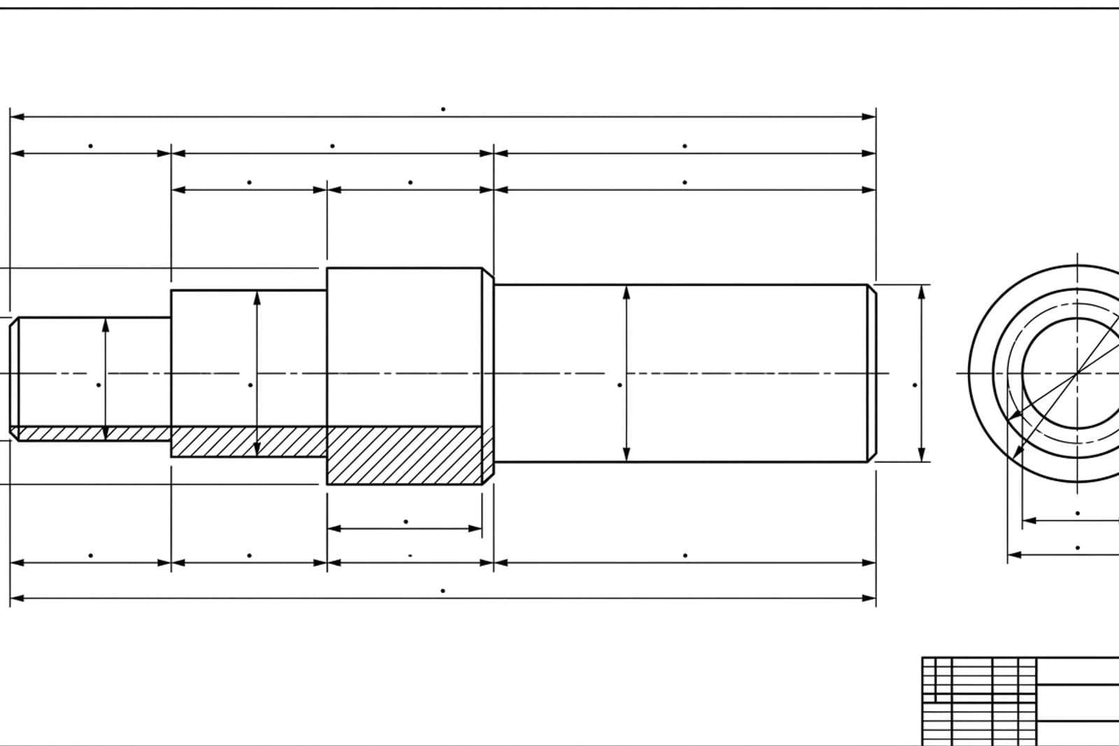
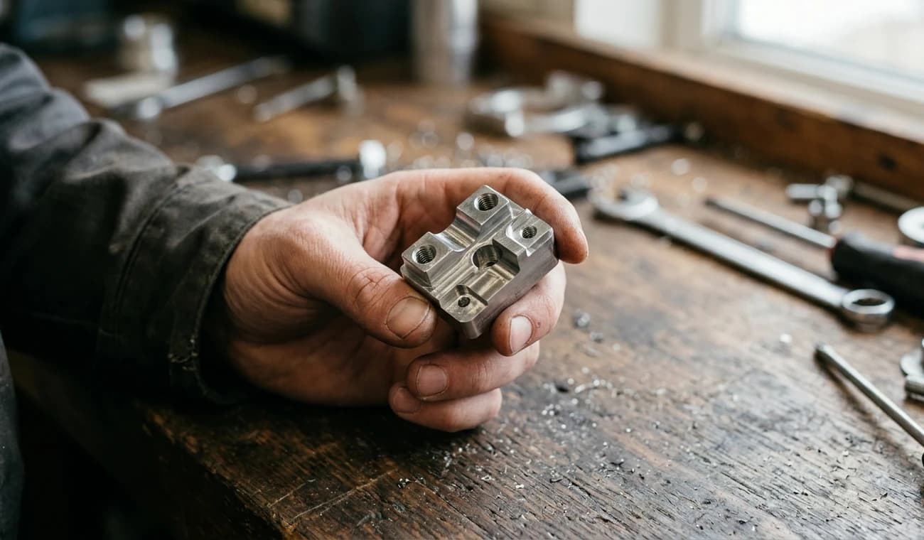
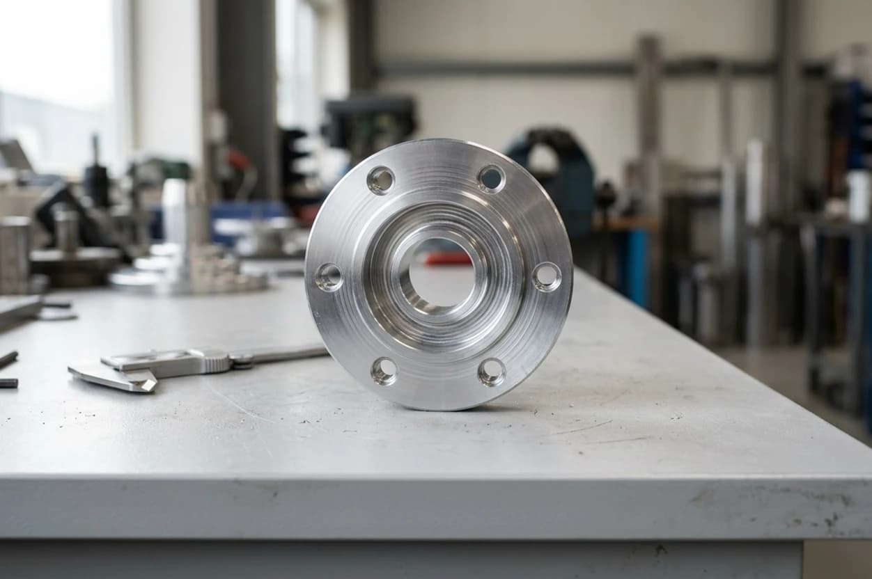
Photograph a discontinued part, get the DXF, extrude or revolve it in SolidWorks, then redesign or detail it. No original model needed.
A part fails on site, someone snaps a photo, and an engineer has a SolidWorks model to modify the same afternoon.
For laser, waterjet or router work the DXF often goes straight to the machine; SolidWorks just confirms and details the geometry.
Generate a first 2D concept from a text description, import it, and pressure-test the geometry in SolidWorks before committing.
Who does what
Division of labour, not redundancy. Each tool owns the half of the job it's actually good at.
| Step in the job | TechDraw AI | SolidWorks |
|---|---|---|
| Capture from a photo | ✓ | ✗ |
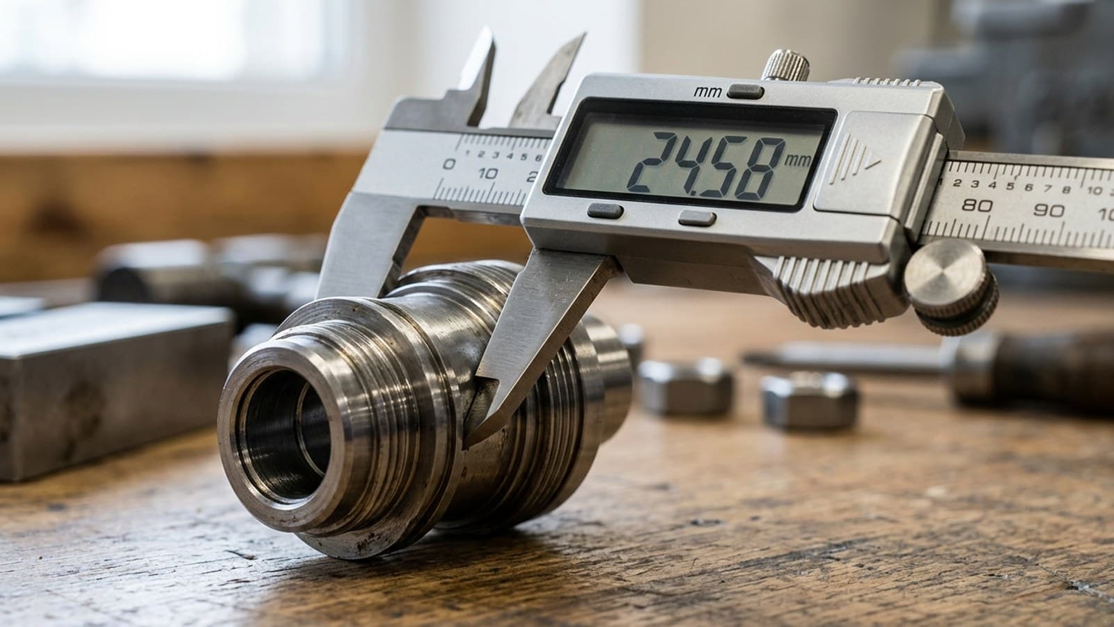
| Real measured dimensions | ✓ | ~ |
| Dimensioned 2D drawing | ✓ | ~ |
| DXF / DWG export | ✓ | ✓ |
| Parametric 3D model | ✗ | ✓ |
| Assemblies & mates | ✗ | ✓ |
| Drawings, GD&T & simulation | ✗ | ✓ |
| Best at | Photo → drawing | Drawing → 3D |
See it for yourself
Drop in a photo of a part. You'll get a dimensioned drawing and a clean DXF, ready for the SolidWorks Import Wizard. No account needed to start.
The five-step handoff
Once you've exported the drawing from TechDraw AI as a DXF, the import into SolidWorks is short. If your part is flat, like a gasket, bracket or laser plate, the DXF is the production file and you can stop after step 2.
The seam is a DXF. Mind your units, layers and closed loopsand it's a seam you barely notice. Geometry in, parametric model out.
Extrude vs. revolve
The DXF is always a flat 2D profile. How you give it depth depends on the part.
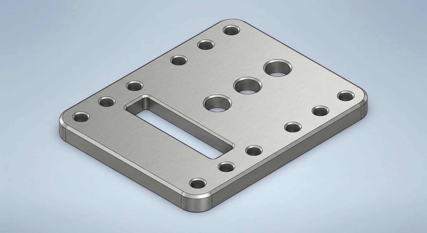
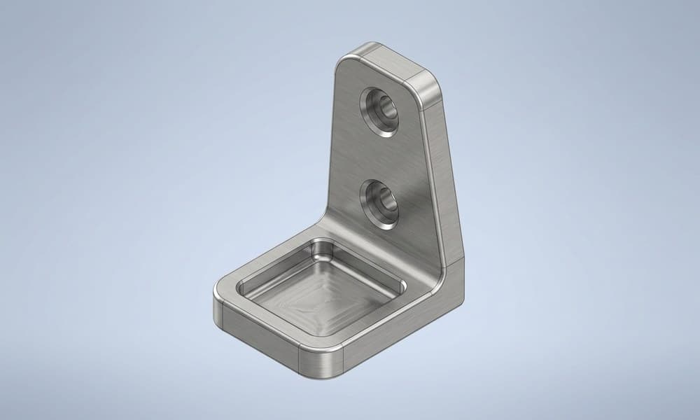
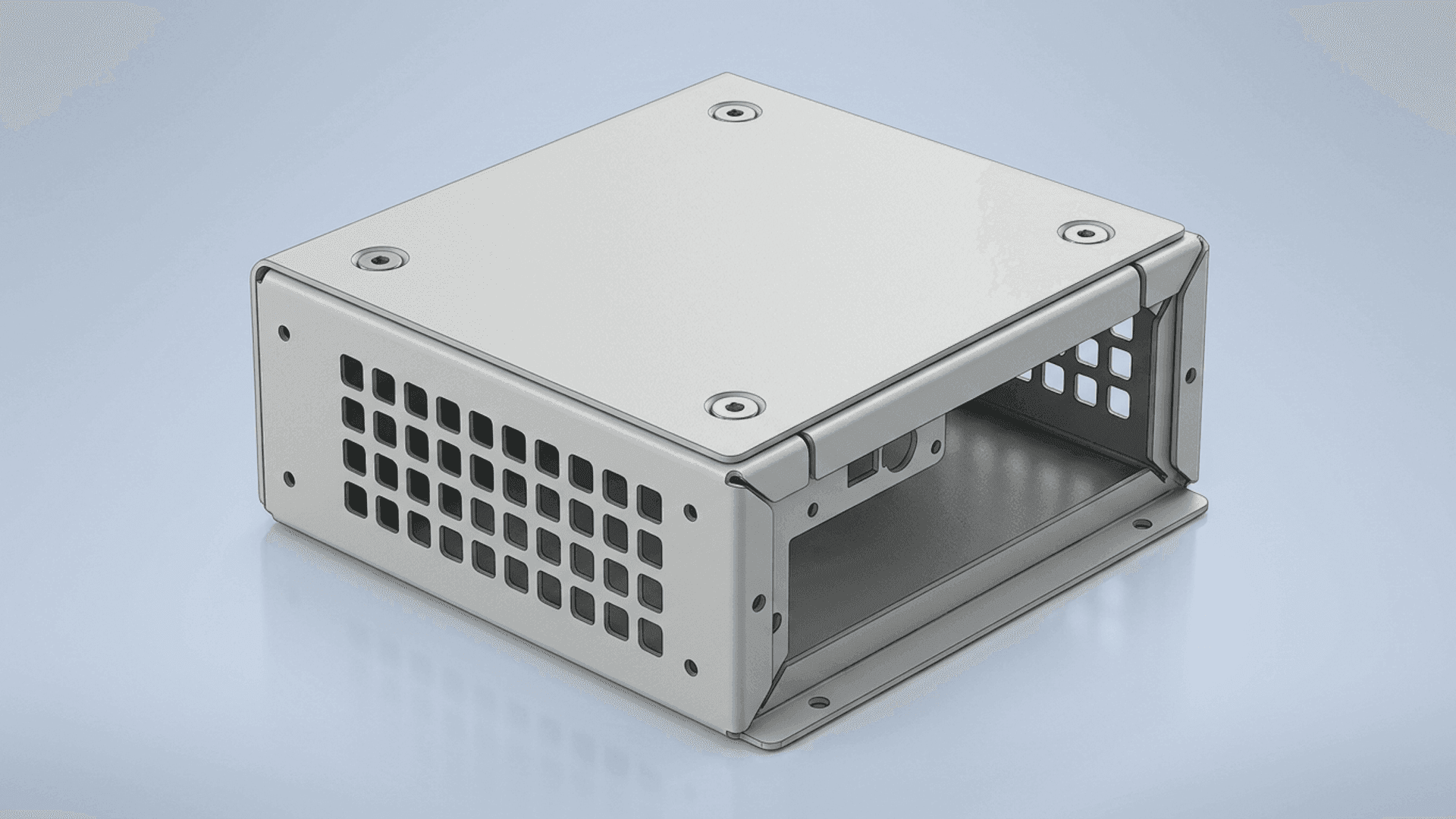
- Brackets, plates, housings, constant cross-section
- Select the closed contour, extrude to thickness
- Closed cut-outs become pockets with Extruded Cut
- Convert Entities pulls the DXF into a fresh sketch
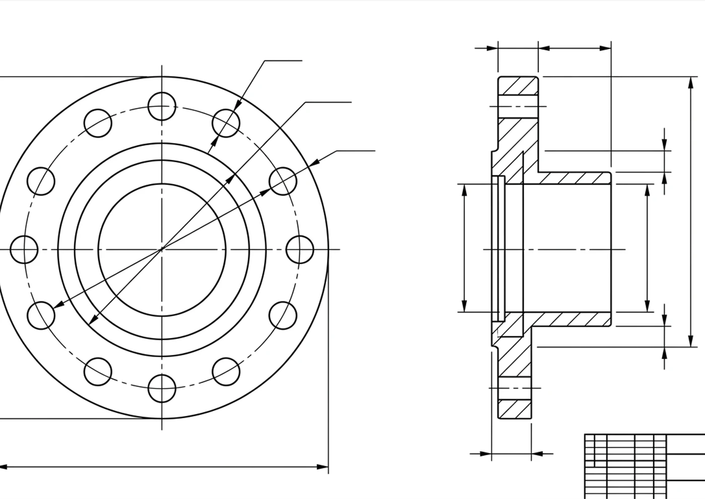
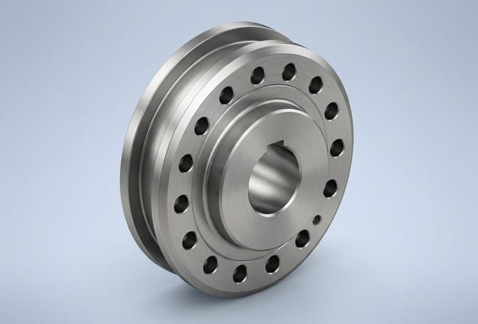
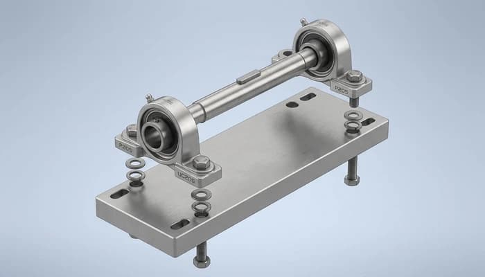
- Shafts, bushings, pulleys, anything round
- Keep just the half-section profile
- Add a centerline as the axis, revolve 360°
- Revolved Cut handles grooves and reliefs
Three gotchas that break the import
Almost every “my DXF won't extrude” thread comes down to one of these. Knowing them up front saves the ten minutes.
Cleanest habit: from TechDraw AI, export one DXF of just the profile geometry for modelling, and keep the full dimensioned drawing (or a PDF) open beside SolidWorks as your spec. The model gets clean lines; you keep the numbers in view.
Where this combo earns its keep
| Job | TechDraw AI | SolidWorks |
|---|---|---|
| Capture an undocumented part | ||
| Dimension it to real size | ||
| Build the 3D model | ||
| Redesign / modify | ||
| Detail drawing & GD&T |
Other CAD workflows
TechDraw AI hands a clean, dimensioned DXF to whatever you model in. Here's the same photo-to-3D handoff written up for other CAD tools.
The full hub: every TechDraw AI photo-to-DXF pairing in one place.
TechDraw AI + Fusion 360Insert the DXF into a Fusion sketch, then extrude or revolve it into a parametric model.
TechDraw AI + OnshapeImport the DXF, Use the curves in a Part Studio and model it in the browser.
TechDraw AI + Shapr3DImport the DXF onto a sketch plane, then Push/Pull or revolve it on iPad or Mac.
TechDraw AI + FreeCADImport the DXF in the Draft workbench, convert it to a sketch, then Pad or Revolve it — free.
TechDraw AI + InventorImport the DXF into a sketch, extrude or revolve it, then drive a production drawing and BOM.
TechDraw AI + SketchUpImport the DXF in SketchUp Pro, explode it to edges, then Push/Pull or Follow Me into a model.
TechDraw AI + TinkercadExport as SVG, import it into Tinkercad in the browser, and extrude it into a printable solid.
TechDraw AI + BlenderImport the DXF or SVG as a curve, convert to mesh, then Solidify or Screw it — free.
TechDraw AI + RhinoImport the DXF as exact curves, Join them, then ExtrudeCrv or Revolve into NURBS surfaces.
Start at the part, end at the 3D model
Generate the dimensioned DXF in minutes, then take it into SolidWorks. No tracing, no blank canvas. Free to start, no account needed.
Frequently asked questions
Does TechDraw AI replace SolidWorks?
Not at all. They solve different halves of the job. TechDraw AI gets you from a physical part or an idea to a dimensioned 2D drawing and a clean DXF in minutes. SolidWorks is where that DXF becomes a parametric 3D model, an assembly, a detailed drawing or a simulation.
How do I open a TechDraw AI drawing in SolidWorks?
Export the drawing as DXF from TechDraw AI, then in SolidWorks choose File › Open and select the DXF. The DXF/DWG Import Wizard opens: pick 'Import to a new part as a 2D sketch', set the units, and finish. The geometry lands as a sketch you can extrude, revolve, detail or use as a cut profile.
Why won't my imported DXF extrude in SolidWorks?
Extruded Boss/Base needs a closed contour. If the Contour Select Tool won't pick a region, two endpoints that look joined aren't. Run Tools › Sketch Tools › Repair Sketch to find the gaps and remove duplicate or overlapping entities. A clean export from TechDraw AI is already closed, so this mostly bites hand-traced DXFs.
Do I lose the dimensions when I import the DXF?
The dimension text comes in on its own layer as sketch text and annotation, not as driving dimensions, and that holds for any DXF in any CAD package. Keep that layer for reference and re-apply the Smart Dimensions you care about as SolidWorks sketch relations.
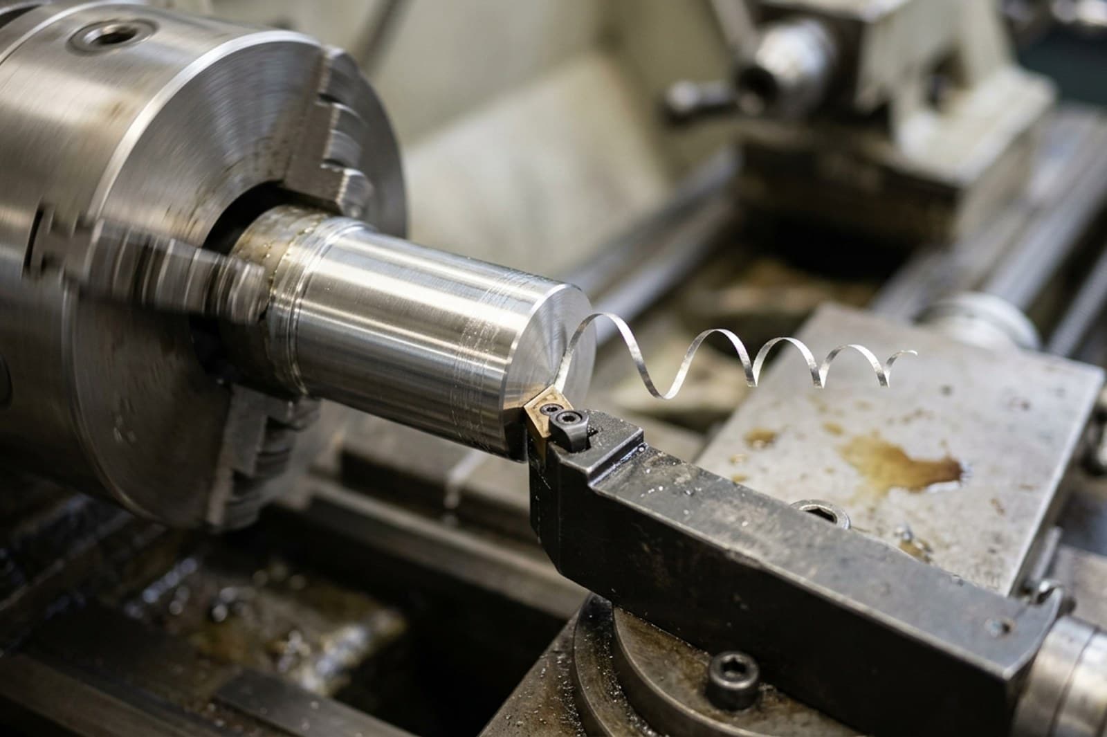
Does this work for turned (round) parts too?
Yes. For a shaft, bushing or any part with an axis of revolution, import the DXF profile, keep just the half-section, add a centerline as the axis, and use Revolved Boss/Base instead of Extruded Boss/Base.