"Image to CAD" sounds solved: drop in a JPG, get a CAD file out. The conversion is real. The trap is what you think you are getting. Most tools that rank for this search trace an outline, and a traced outline has no size, no scale, and nothing a machine shop can cut from. This is the route to a drawing you can actually build from.
The short answer
You can turn a JPG into a CAD drawing, but only a tool that ties the image to a real measurement gives you something you can manufacture from. Plain raster-to-vector converters trace the edges in your image and hand back a clean, completely sizeless vector outline. You can do exactly that with our free image to DXF converter, and we line up the alternatives in the best JPG to DXF converters, and converting a JPG to CAD drills into the trace-versus-redraw decision for a photo specifically. The question that decides whether your file is useful is blunt: can a machinist trust a dimension off it?The rest of this guide is about getting to "yes."
Raster vs vector vs CAD: what is actually measurable
Three different things get called "a CAD file," and they sit on a ladder of how far you can trust them. Knowing your rung is most of the battle.
Raster (JPG, PNG): pixels, no real units
A photo is a grid of pixels. A pixel has no physical size, and nothing in a JPG says "this edge is 60 mm." Raster carries no inherent dimension or scale. It is a picture of a part, not a description of one.
Vector (SVG, DXF): math paths, scalable but not sized
Vectorizing turns those pixels into mathematical paths (lines, arcs, polylines) that scale forever without blur. Real geometry, but relative: a DXF stores exact coordinates, yet those numbers only mean millimetres once you tie them to the real world. Until then the same file can be scaled to any size, which is precisely why it is not yet trustworthy.
Parametric CAD (DWG model, STEP): true geometry
At the top sits true CAD: geometry with assigned real units, and for STEP, exact solid math. This is the manufacturable level. Every workable image-to-CAD recipe is really about walking your photo up this ladder, and the step most tools quietly skip is adding a reference measurement.
How image-to-CAD conversion really works
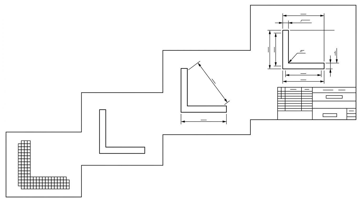
Under the hood, a raster-to-vector converter does edge detection and tracing: it finds the lines in your image and redraws them as vector entities, literally tracing over the pixels with paths. Clean, high-contrast line art traces beautifully. A busy photo full of shadows and reflections traces into a tangle you spend an afternoon cleaning up.
Even a perfect trace, though, reproduces the proportions in pixels, not millimetres. And here is the physics no converter can engineer around. A single photograph cannot reveal the absolute size of an object. Under perspective projection a 40 mm bracket photographed up close and a 400 mm bracket photographed from far away produce the same pixels. The research is blunt about it: this ambiguity is "inherent to the projective nature of image formation," and resolving it requires a known reference in the scene. So a JPG-to-DXF outline is dimensionless because the size was never in the photo to begin with.
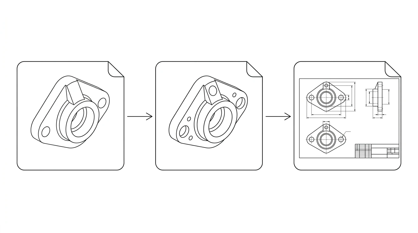
Photo to a real CAD drawing, step by step
- Take the right photo. Shoot straight on, camera parallel to the face you care about. Angles bend straight edges and distort proportions. Fill the frame, use even light, and keep a high-contrast plain background so the edges read cleanly.
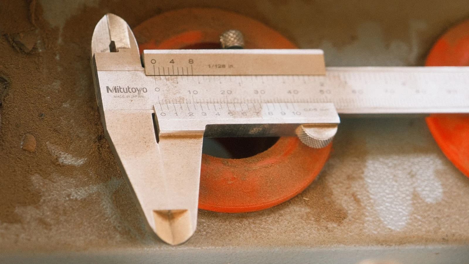
- Add a known reference. Measure one feature with a caliper, or lay a ruler in the shot. That single known length is what turns shape into size.
- Convert to vector geometry. Trace the image to clean paths (outlines, holes, symmetry), dropping noise and closing gaps.
- Scale to the reference, then dimension. Tie the geometry to your known measurement so the whole drawing is to scale, and add the dimensions — plus any tolerances or GD&T symbols — that make it manufacturable.
- Clean up. Close open paths, merge duplicate lines, and delete stray artifacts so the file is CAD-clean rather than a heap of fragments.
- Export the right format. DXF for 2D and sheet metal, DWG if your recipient lives in AutoCAD, PDF for a human to read.
DXF vs DWG vs STEP: which file does a shop want?
Exporting the wrong format is a quiet way to slow a quote down. For a part recovered from a photo, the choice is usually clear.
Choosing a CAD file format from a photo-based drawing
| Format | Dimension | Best for | From a photo? |
|---|---|---|---|
| DXF | 2D | Laser, CNC router, sheet metal, universal exchange | Yes, the right default |
| DWG | 2D / 3D | Recipients working natively in AutoCAD | Yes (2D) |
| STEP | 3D | 3D CNC, the standard for solid geometry | No, needs true 3D capture |
DXF is the open, neutral 2D format Autodesk introduced with AutoCAD in 1982, which is why almost every CAM package and cutting machine reads it. STEP is the standard for 3D, but a single photo cannot produce honest 3D solid geometry, so it is out of scope for a photo-to-2D job. More on this in CAD file formats for manufacturing, and on the DXF route specifically in how to convert an image to DXF.
What "image to CAD" tools can't do
Read this before you trust any converted file.
- Cosmetic vectorizing is not a measurable drawing. A traced outline with no reference is shape at an unknown scale.
- AI "stylized" output is not manufacturable. Tools that render a photo into blueprint art produce a picture, not geometry. We watched one invent a 2.5-metre dimension on an 80 mm part in our ChatGPT test.
- No reference means no scale. The better tool docs admit a photo-realistic trace is unsuitable for most practical uses without redrawing and scaling it.
- One photo is not 3D. Internal bores, the far side and true depth are invisible to a single image. A 2D drawing is the ceiling.
For the wider map of which tool does which job, see the best AI technical drawing tools.
How TechDraw AI does it differently
TechDraw AI is an AI image to CAD converter built around the step the tracers skip. You photograph the part and enter one real measurement. The AI reads the topology, lays out orthographic views, and scales the whole drawing to your reference so every dimension is anchored to reality instead of to pixels. You confirm the dimensions that carry your design intent, then export a dimensioned DXF, DWG, SVG or PDF a shop can quote against.
And because the export is a clean DXF, the drawing doubles as the seed of a 3D model. Our CAD workflow guides walk through importing it into Fusion 360, FreeCAD or Shapr3D and extruding it into a parametric part.
It stays honest about the ceiling: a measurable 2D drawing, not a magic 3D STEP solid conjured from one photo. That is the line between a file that looks like CAD and one you can build from. The reasoning runs deeper in from photo to manufacturing drawing, and the quick walkthrough lives in how to convert a photo into a technical drawing.
Starting from a rough sketch rather than a photo? The sketch to CNC-ready DXF workflow covers that path, and cleaning up a jagged trace covers getting smooth vectors out of any image.
Frequently asked questions
Can you convert a photo (not a drawing) of a real part to a CAD file?
Yes, with one caveat that decides everything: the conversion gives you the shape, not the size. A photo has no inherent scale, so a traced or AI-generated outline is dimensionless until you anchor it to one known measurement. With a reference dimension you get a real, to-scale CAD drawing; without one you get a nice-looking outline you cannot manufacture from.
Is a JPG-to-DXF conversion accurate and to scale?
The geometry tracing can be clean, but it is not automatically to scale. Vectorizing a JPG reproduces the proportions in pixels, not real-world units — the output can be scaled to any size, which is exactly the problem. It only becomes accurate once you assign a real unit using a known reference dimension in the image.
How do I convert a JPG to DXF for free?
Free raster-to-vector tools like Vectorizer.AI, Convertio or Inkscape's trace will turn a high-contrast JPG into a DXF outline. They work best on clean line art and logos, not busy photos, and they give you shape only — no dimensions, no scale. For a measurable drawing you need a tool that adds a reference measurement and dimensioning.
What is the difference between DXF and DWG?
DWG is Autodesk's native, proprietary CAD format; DXF (Drawing Interchange Format) is the open, neutral format Autodesk publishes so other software can read the same geometry. For 2D and sheet-metal work, DXF is the safe universal deliverable; DWG is best when the recipient is working in AutoCAD.
Can you get a 3D STEP file from a single photo?
Not really. A single 2D photo cannot capture true 3D geometry — it cannot see the far side, internal features or absolute depth. Tools that claim a full STEP solid from one photo are guessing. For a flat or 2.5D part, a dimensioned 2D DXF is the right and achievable deliverable.
Sources
- Single View Metrology in the Wild (ECCV 2020) — scale is unrecoverable from one image without a known reference
- Scan2CAD — Converting Raster to Vector: An Introduction
- Scan2CAD — Converting Photos to CAD: what is (and isn't) possible
- Vectorizer.AI — JPG to DXF Converter (vector output has no native size)
- 3ERP — CAD File Formats for CNC Machining (DXF, DWG, STEP explained)
- AutoCAD DXF — format history and structure (Wikipedia)
- Library of Congress — DXF (AutoCAD Drawing Interchange Format), ASCII variant