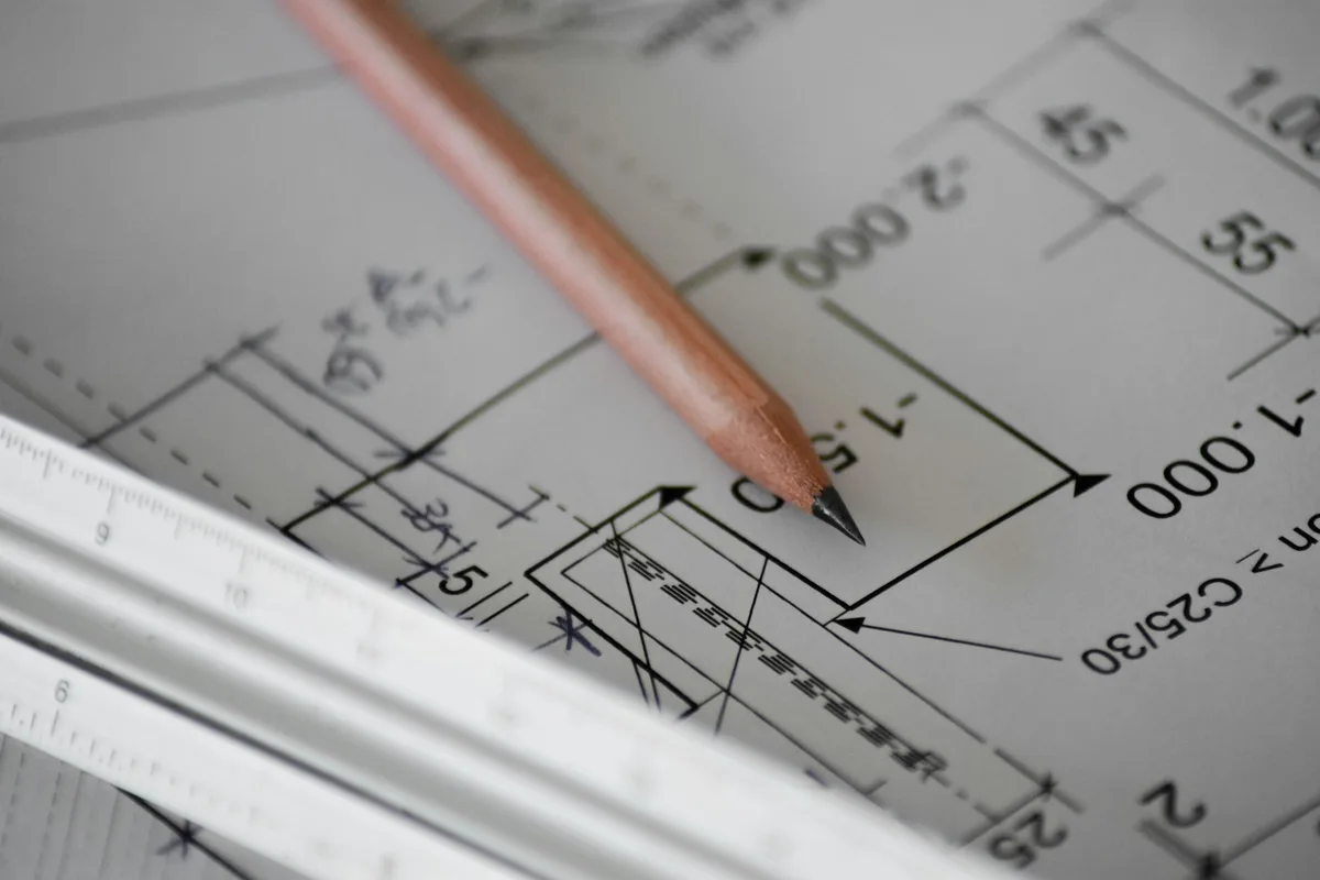
You sketched a bracket, a sign, a bracket plate or a one-off part on paper, and now you want a machine to cut it. The gap between that pencil line and a CNC router is smaller than it looks, but it is real: the machine cannot read your drawing, only a precise set of paths. This is the workflow that gets you from paper to a clean, cuttable DXF, step by step, without owning a full CAD seat.
Why a sketch isn't a CNC file
A CNC router, laser or plasma cutter does one thing: it drives a tool along paths. Those paths are vector geometry, lines, arcs and closed contours, with real coordinates. A sketch on paper, or a photo of it, is the opposite: a field of pixels or ink with no concept of a line the machine can follow. So “turning a sketch into a CNC file” really means three things in sequence: capture the drawing as an image, trace that image into vectors, and save those vectors as a DXFthe machine's software can read.
DXF is the format to aim for because it was built as an exchange format and opens in nearly every CAM and CAD tool. If you want the wider picture of where DXF sits next to DWG, STEP and PDF, see which file to send your manufacturer and the difference between DWG and DXF. For now, DXF is the target.
1. Draw it so it traces well
The single biggest lever on the final result is the sketch itself. A tracer follows the boundary between dark and light, so the cleaner that boundary, the cleaner the vectors. A few habits make a large difference:
- Dark pen, white paper. A fine felt-tip or a black marker on plain white traces far better than faint pencil. High contrast is everything.
- Close every shape you want to cut. A profile the machine cuts out has to be a closed loop. If two lines should meet at a corner, make them actually meet on paper.
- Keep lines clean and single. Avoid sketchy, double-stroked outlines and shading. The tracer reads every stray mark as geometry, so a scribbled fill becomes dozens of junk paths.
- Use a straightedge for straight edges. Anything you want straight or circular, draw with a ruler or a template. A wobbly freehand line traces as a wobbly cut.
2. Photograph or scan it cleanly
Next, get the sketch into the computer as an image. A flatbed scan is the gold standard because it is flat, evenly lit and distortion-free, but a phone photo works well if you respect a few rules:
- Shoot straight down. Hold the camera parallel to the paper. An angled shot adds perspective distortion, and that distortion ends up in the part you cut.
- Light it evenly. Diffuse daylight is ideal. Make sure no shadow, especially your own, falls across the drawing, and avoid glare from a single harsh lamp.
- Fill the frame. Get the paper to fill most of the shot so the lines have enough resolution to trace, then crop to just the drawing.
- Keep it sharp. A blurry photo blurs the edges, and soft edges trace into ragged contours. Tap to focus before you shoot.
Phone photos often land as HEIC or JPG, which is fine. The tracing step accepts ordinary image formats; what matters is contrast and sharpness, not the file type.
3. Trace it into vectors and DXF
This is the conversion that does the real work: turning the image into vector outlines and exporting a DXF. You have two practical routes.
The fast route is an automatic tracer. Our free image to DXF converter runs in your browser: drop in the photo or scan of your sketch, tune the trace threshold until the outline is crisp, and download closed DXF polylines. It is built for exactly this hand-off, from a high-contrast line drawing to cuttable vectors, with nothing to install. The same approach is covered from the image side in image to CAD, and we compare the dedicated tools in the best JPG to DXF converters.
The manual route is to trace by hand in a vector editor such as Inkscape (free) or Adobe Illustrator. You can auto-trace the bitmap and then redraw or correct paths with the pen tool, then export DXF. This gives you the most control and is worth it when the auto-trace fights a messy sketch, but it is slower and has a learning curve.
4. Clean up the DXF
A freshly traced DXF almost always needs a tidy-up before a machine should touch it. The same rules apply whether you traced automatically or by hand:
- Close open contours. Any profile you want cut out must be a closed loop. Tracers sometimes leave a tiny gap where two endpoints nearly meet; join them.
- Delete duplicate and stray lines. Overlapping paths make the tool cut the same line twice, and stray specks from paper texture become tiny unwanted cuts. Remove them.
- Simplify the geometry. Auto-tracing can produce hundreds of nodes on a curve that needs ten. Smoothing and reducing nodes gives a cleaner cut and a smaller file.
- Prefer simple entities. Lines, arcs, circles and polylines import most reliably. If your editor exports splines, many CAM tools handle them, but converting to polylines removes any doubt.
If your final operation is laser, plasma or waterjet rather than a router, the file rules are nearly identical; we cover them in depth in how to prepare a DXF for laser cutting.
5. Set the real size
This is the step people skip, and it is the one that scraps material. A traced DXF captures the shape of your sketch, but it has no idea how big the real part is, because your drawing was never to scale. The contours come in at whatever size the tracer guessed.
Before you cut, set the geometry to its true dimensions. The reliable way is to pick one feature you know the real measurement of, a hole spacing, an overall width, an edge length, and scale the whole drawing until that feature reads correctly. Then confirm the units: a DXF does not strictly enforce millimetres versus inches, so a file meant to be 100 mm can open as 100 inches if the unit is wrong.
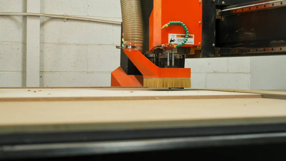
6. From DXF to toolpath
The DXF is not what the machine runs. The controller runs G-code, the line-by-line instructions for where the tool moves, how fast and how deep. Turning your DXF into G-code is the job of CAM software, which ships with most machines (Carbide Create, Easel, LightBurn, VCarve and similar). In CAM you:
- Import the DXF and confirm it came in at the right size.
- Choose the operation for each contour: profile cut, pocket, engrave or score.
- Set the tool, depth, feeds and speeds for your material and bit.
- Decide where the tool runs relative to the line, inside, outside or on it, so the part comes out the right size.
- Generate the G-code and send it to the machine.
That tool-offset choice matters: cut on the outside of a line for an outer profile, the inside for a hole, or the part will be off by the tool radius. For more on what a manufacturer or shop expects when you hand off a file, see what makes a drawing manufacturing-ready.
Where this works and where it doesn't
Be honest with yourself about what a traced sketch can and cannot do, because it sets your expectations correctly.
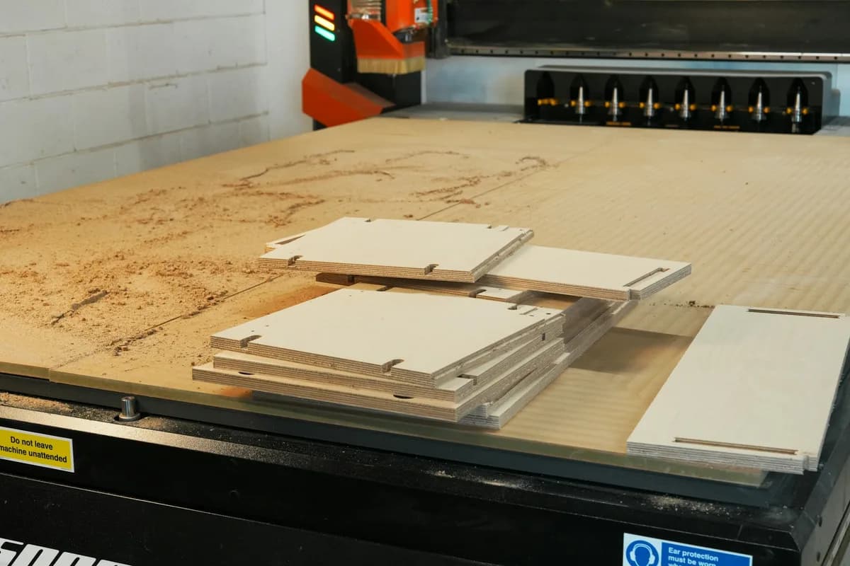
It works well for outline-driven parts: signs, brackets, gaskets, templates, decorative panels, enclosure faces, anything defined mostly by its 2D profile. If the shape is the point, tracing is the fastest path from idea to cut part, and it is exactly what this workflow is for.
It struggles when precision is the point. A traced outline is only as accurate as your drawing and your scaling. For parts with tight tolerances, mating features, exact hole positions or anything that must fit another component, you want a real measured drawing, not a trace. That means building the geometry in CAD with true dimensions, or reverse-engineering the part from measurements. The trace gives you a shape; engineering gives you a part that fits. Knowing which one you need is half the battle, and going from a photo to a manufacturing drawing walks through the higher-precision end of this.
The full workflow at a glance
Run through this and you will have a file the machine can cut:
- Redraw clean in dark pen on white, closed shapes, straightedge for straight lines.
- Capture with a straight-on, sharp, evenly lit photo or a scan.
- Trace the image into closed vector contours and export a DXF.
- Clean up: close loops, delete duplicates, simplify nodes, prefer simple entities.
- Scale to one known dimension and confirm the units.
- CAM: import, assign operations, set the tool offset, generate G-code.
- Sanity-check the size on the machine before you commit a full sheet.
The hardest-looking step, the trace, is the one you can hand off. Drop a photo of your sketch into the image to DXF converter and you will have closed vectors to clean up in under a minute, then it is just scale and cut.
Frequently asked questions
Can you CNC a hand-drawn sketch?
Not directly. A CNC machine follows toolpaths built from vector geometry, and a sketch on paper is just ink. To cut it, you trace the sketch into vector outlines, export a DXF, set the real dimensions, then generate a toolpath in CAM software. The drawing is the starting point, not the file the machine reads.
How do I convert a hand sketch to a DXF file?
Photograph or scan the sketch as a clean, high-contrast image, then trace it into vector contours and export a DXF. A free in-browser tool can do the tracing step, or you can trace by hand in Inkscape or Illustrator. After exporting, set the units and real size, because a traced DXF carries the shape but not the scale.
What file format does a CNC machine need?
Most 2D CNC routers, lasers, plasma and waterjet cutters read DXF, and the machine's CAM software turns that DXF into G-code, the actual instructions the controller runs. DXF is the safest format to aim for because it is an open exchange format that nearly every CAM program imports. Some workflows accept SVG or DWG instead.
Can I use a photo of my sketch instead of a scan?
Yes. A phone photo works as long as it is sharp, evenly lit and shot straight on, with no shadow falling across the paper. A flatbed scan is cleaner, but a good photo of a dark-pen drawing on white paper traces almost as well. Avoid angled shots, because perspective distorts the geometry you are about to cut.
Do I need CAD software to CNC a sketch?
You need something to produce vectors and something to generate the toolpath, but neither has to be full CAD. You can trace the sketch with a converter or a vector editor, then load the DXF into the CAM software that ships with most machines. Full CAD only becomes worth it when you need exact dimensions, tolerances or parametric edits rather than a traced outline.