
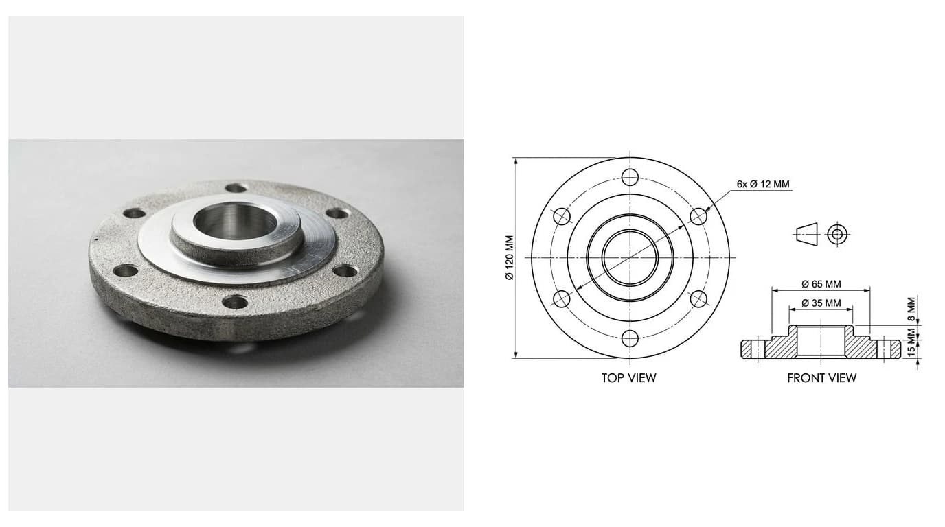
“JPG to DWG” sounds like a file conversion, the way a JPG turns into a PNG. It is not one. A JPG is a grid of coloured pixels. A DWG is a database of lines, arcs and dimensions with real units attached to them. Nothing in your photo is a line yet, so something has to rebuild the picture as geometry first, and then give that geometry a size the picture never carried. Do both and AutoCAD opens a drawing you can dimension, edit and quote from. Skip either one and you get a fuzzy outline sitting at the wrong scale.
Our articles are still written by humans!
Get human written articles in your Google feed.
Convert your JPG to DWG right here
Open the full converter pageDrop a file here. It never leaves your browser.
PNG, JPG, WebP, GIF, BMP, HEIC, TIFF, AVIF · any size · free · DWG or DXF · works best on clean line art, logos and high contrast shapes
The short answer
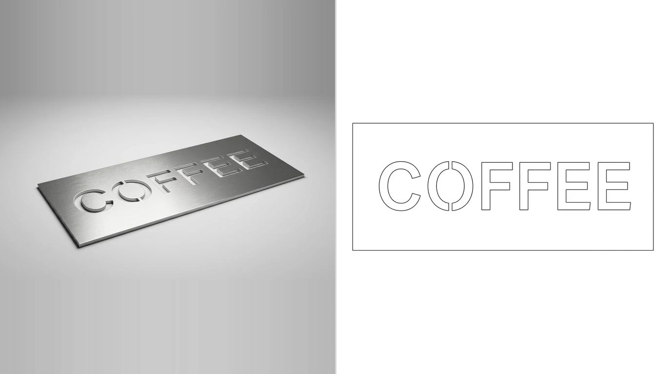
Look at the JPG first, because it decides the whole job. If the JPG is already a drawing, a scanned blueprint, a floor plan, a logo or flat line art, then a raster to vector converter or a careful manual trace gets you faithful linework, and saving that as DWG is a genuine conversion. You still have to set the real scale afterwards, but the shapes are honest.
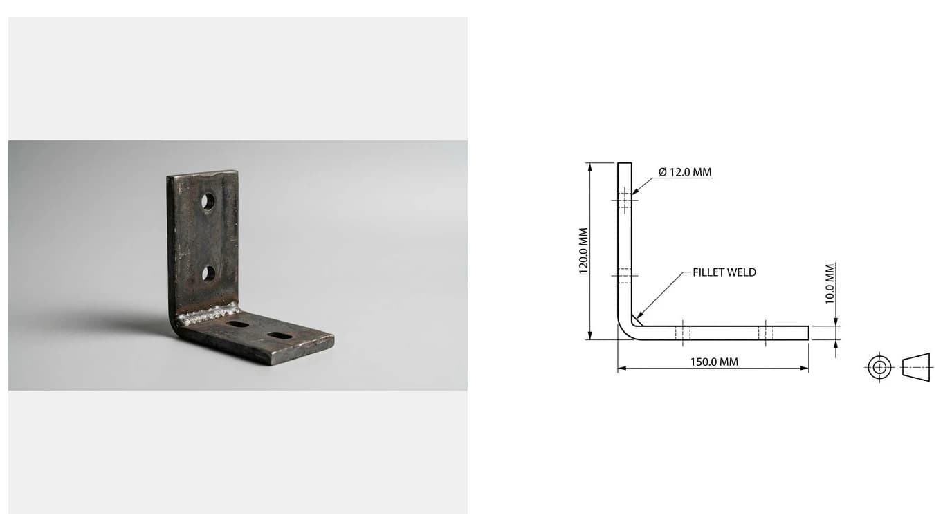
If the JPG is a photograph of a physical object, a trace gives you the outline of one silhouette from one angle, with no inner features, no hidden detail and no sizes. That is not a drawing, it is a shadow. To get a DWG worth sending you have to rebuild the part as orthographic views and anchor those views to a measurement you take off the real thing. Our AI technical drawing generator does exactly that step, and the rest of this page is about knowing which of the two situations you are actually in.
What a DWG stores that a JPG does not
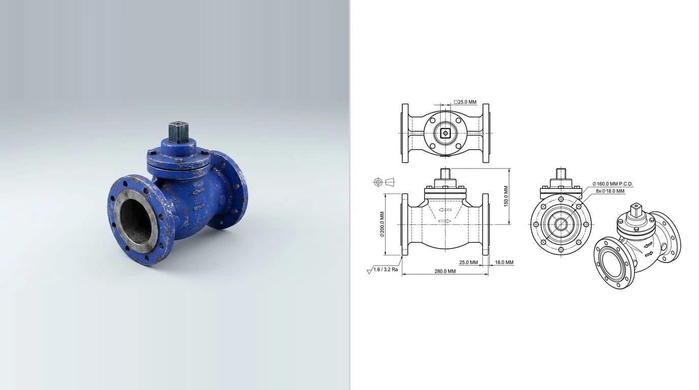
DWG is AutoCAD's native format and it has been around since 1982. Inside it is not a picture at all. It is a structured database: lines, arcs, circles and polylines with coordinates, plus layers, blocks, text, and dimension objects that stay associated with the geometry they measure. Change a line and the dimension attached to it updates. That association is the thing you are actually buying when someone asks for a DWG rather than a picture.
A JPG has none of that. It is a rectangle of colour values, compressed with a method built for photographs, which throws away the detail your eye is least likely to miss. That works beautifully for holiday snaps and works against you here, because the detail it throws away lives exactly where the edges are. For the wider map of which format each machine and shop expects, see CAD file formats for manufacturing.
Drawing or photograph? The fork
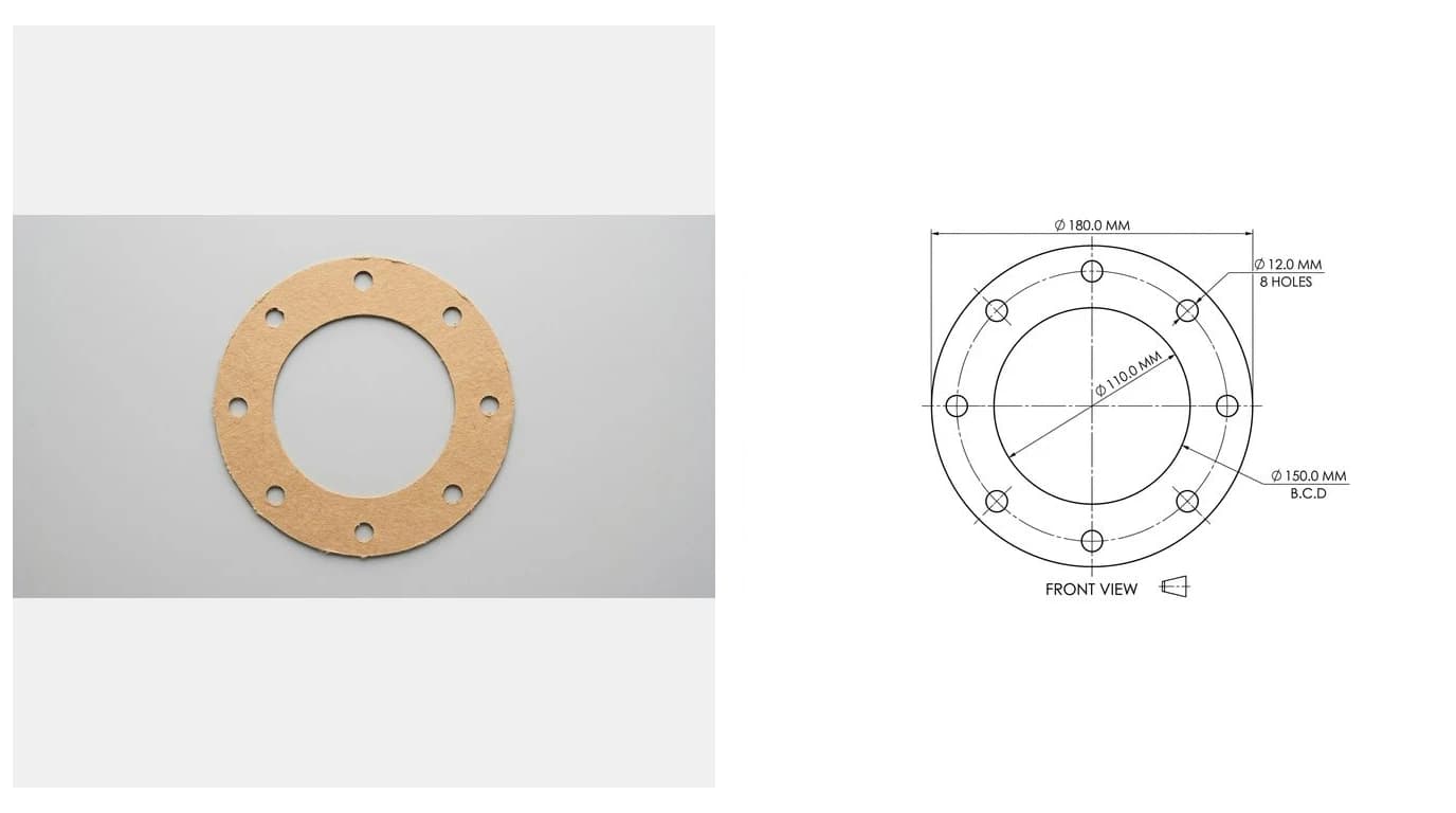
This is the single decision that determines whether your conversion works, and most people skip it. A flat gasket photographed straight down is nearly a drawing already. Every edge that matters is in one plane, facing the camera, with nothing hidden behind anything else. Trace that and you get real geometry, because there was no third dimension to lose.
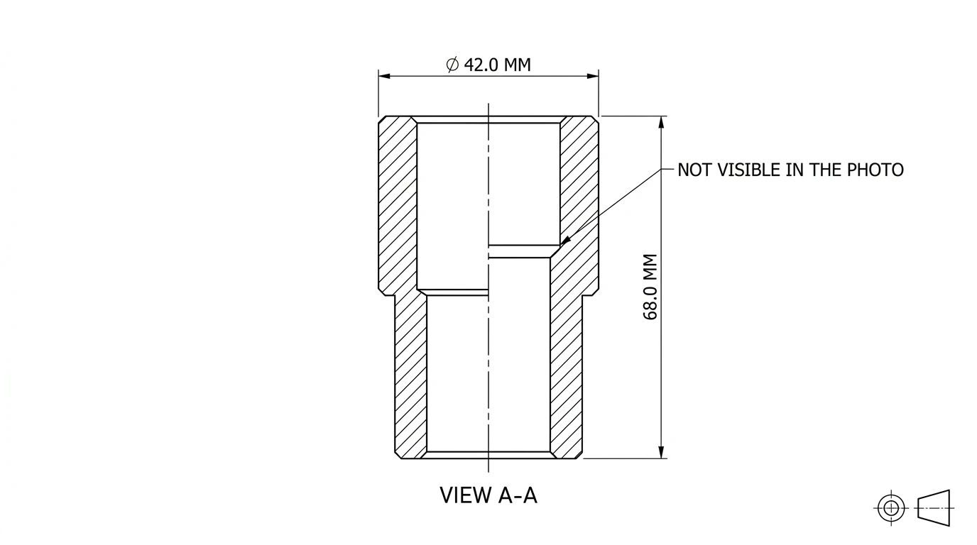
Now photograph a bushing standing on a bench. The camera sees an outside diameter and the top face. It cannot see the bore stepping down inside, the chamfer on the far end, or the wall thickness. No tracer recovers those, because they were never in the pixels. A person who knows what the part is has to put them there, which is why measuring the part properly is not an optional extra step.
Three routes from JPG to DWG
There are only three, and they suit different inputs. Picking the wrong one is how people end up with a DWG full of jagged doubled lines.
1. Attach and trace inside AutoCAD
Use ATTACH to bring the JPG in as an underlay, scale it to a known dimension, then draw over it on a separate layer with LINE, PLINE and ARC. Slow, fully under your control, and the result is native DWG with no conversion artifacts at all. This is the right route when accuracy matters more than time and the source is a drawing. The full walkthrough is in image to AutoCAD.
2. Automatic raster to vector
Tools like the Raster Design toolset, Scan2CAD or the free Inkscape trace the image and hand back vectors. Fast, and genuinely good on clean high contrast line art. On a photograph it follows shadows and compression noise as if they were edges, which is where the jagged output comes from. If your trace came back rough, fixing a jagged vector trace covers the cleanup. For a straight in browser version of this route there is our JPG to DXF converter, which downloads as either DXF or DWG. The same tool has its own page for a JPEG or a PNG if that is what you are starting from.
3. Rebuild it as a measured drawing
Instead of copying the outline, this route reads the object, lays out front, top and side views, and ties every length to one reference measurement you supply. You get hidden detail, real dimensions and a drawing a shop can quote against, which is the whole difference between a picture of a part and a drawing of one.
Which route fits which JPG
Getting the size right
This is where most JPG to DWG conversions quietly fail. A pixel is not a millimetre and never was, so whatever lands in AutoCAD arrives at a size the tool invented. It will look completely convincing. It will also be wrong, and nothing about the file tells you by how much.
The fix is always the same and it always needs you. Measure one real feature on the object with a caliper or a rule, ideally the longest one you can measure accurately, then scale the whole drawing until that feature matches. In AutoCAD that is SCALE, then R for Reference, click the two ends of the known feature, and type the true length. Because the proportions were already right, every other dimension follows from that one number.
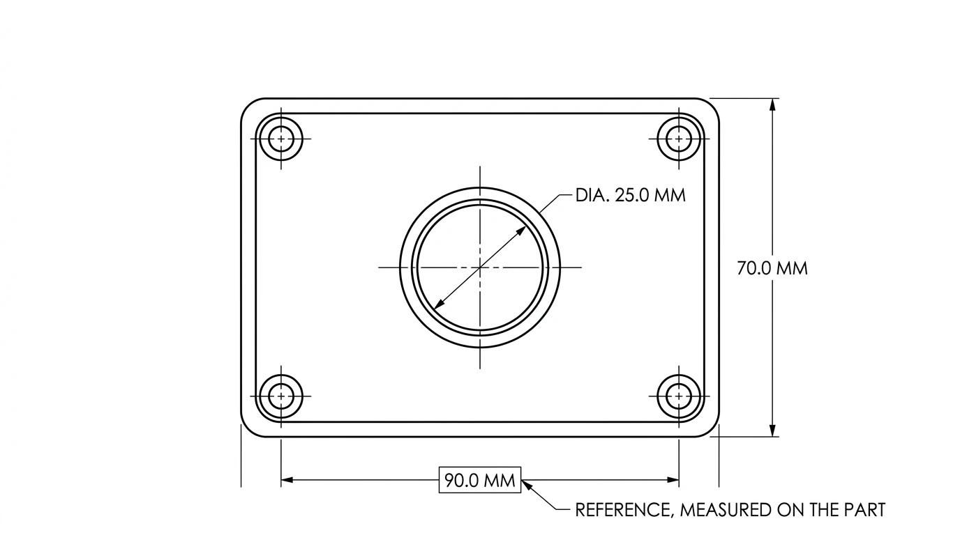
Pick the reference on a feature that is crisp, flat to the camera and undamaged. A worn face or a rounded edge gives you a soft number, and every dimension on the sheet then inherits that softness. Getting dimensions from a photo goes through choosing a good reference in detail, and if a file turns up undersized downstream, why a DXF imports at the wrong size is the same problem seen from the other end.
The DWG version trap
DWG is not one format, it is a family of them, and Autodesk revises it every few releases. The rule that catches people is that DWG is backwards compatible but not forwards compatible. A 2026 seat opens a 2007 file without complaint. A 2018 seat may simply refuse a file saved in the newest format, usually with an unhelpful message that makes it sound as though the file is damaged.
So when the DWG is leaving your machine, save down. AutoCAD 2013 or 2018 format opens practically everywhere and costs you nothing on a 2D part drawing, because none of the newer features are in play. Ask the recipient which release they run if you can, and if you cannot, older is the safer guess.
Should you ask for DWG at all?
Worth a moment, because plenty of people ask for DWG out of habit when DXF would serve them better. DWG is the right answer when the file is going back into AutoCAD or another Autodesk product, since it is native and keeps the most fidelity. DXF is the right answer when the file is going to a laser, plasma, waterjet or CNC shop, because cutting software reads DXF almost universally and often prefers an older R12 flavour.
The good news is that this is a handoff decision rather than a quality one. Any tool worth using exports both from the same drawing, so you can send DWG to the designer and DXF to the cutter without redoing anything. DWG vs DXF has the full comparison, including what each format keeps and drops.
Before you send it
Run these five checks before the DWG leaves your machine. Every one of them costs a minute and each catches a failure that is expensive later.
- Measure one feature in the file and confirm it matches the real object. If it does not, nothing else on the sheet is trustworthy.
- Check the units. Open the drawing and confirm it is in millimetres or inches deliberately, not by accident. A drawing at 25.4 times the intended size is the classic symptom.
- Look for doubled lines. Tracing artifacts often stack two nearly identical polylines on top of each other.
OVERKILLremoves them andPURGEclears the unused layers a converter leaves behind. - Confirm closed profiles if anything is going to be cut. An outline that looks closed on screen but has a gap of a hundredth of a millimetre will stop a cutter.
- Save down a version or two so the recipient can actually open it.
None of this is difficult, it is just the part that gets skipped when a conversion looked like it worked. The picture came out the other side, the shapes are right, and it is genuinely easy to forget that the one thing a JPG never contained was how big any of it is. Anchor that, and the rest of the file is honest.
Frequently asked questions
How do I convert a JPG to a DWG file?
It depends on what the JPG shows. If it is already a drawing, a logo or clean line art, run it through a raster to vector converter and save the result as DWG, or attach it in AutoCAD and trace over it. If it is a photograph of a real object, tracing only copies the silhouette, so you rebuild the part as a dimensioned drawing anchored to one measurement you take yourself, then export DWG. Decide which of the two you have before you pick a tool, because that choice drives everything after it.
Can I convert a JPG to DWG for free?
Yes, with limits. Inkscape traces a clean JPG into vectors for free and exports DXF, which AutoCAD opens and saves as DWG in one step. Free web converters handle a one off file. What none of them give you is real size or dimensions, because a JPG never contained those numbers. Free is genuinely fine for a logo or a scanned drawing. For a part you intend to manufacture it usually is not.
Can AutoCAD open a JPG directly?
AutoCAD can attach a JPG as a raster underlay with the ATTACH command, but that only places the picture in the drawing. The pixels stay pixels. Nothing becomes a line you can dimension or snap to until you trace over it yourself, or run the image through automatic vectorizing with the Raster Design toolset or a third party tool and import the result.
Why is my DWG the wrong size after converting a JPG?
Because a JPG has no units. It is a grid of pixels, so a converter can only reproduce the shape, not how big it is in millimetres. The DWG arrives at whatever scale the tool guessed. Fix it by measuring one feature on the real object, then scaling the whole drawing until that feature matches, using the SCALE command and its Reference option. Do it before anyone quotes or cuts from the file.
Is there an AI that converts a JPG to DWG?
Yes, and it works differently from a tracer. Instead of following the visible outline, it reads the object in the photo, lays out orthographic views, and ties every length to one reference measurement you type in, then exports DWG, DXF, SVG or PDF. That is the part a tracer cannot do, because a tracer has no way of knowing what the object is or how large it is.
What DWG version should I export?
When in doubt, an older release such as AutoCAD 2013 or 2018. DWG is backwards compatible but not forwards compatible, so a newer seat opens an old file happily while an older seat may refuse a brand new one. Most export dialogs let you pick. Older is the safer handoff, and you lose nothing on a simple 2D part drawing.
Should I convert my JPG to DWG or to DXF?
DWG if the file is going back into AutoCAD or another Autodesk product, since it is the native format. DXF if it is going to a laser, plasma or CNC shop, because cutting software reads DXF almost universally. Any decent tool exports both from the same drawing, so this is a handoff decision rather than a conversion quality decision.