
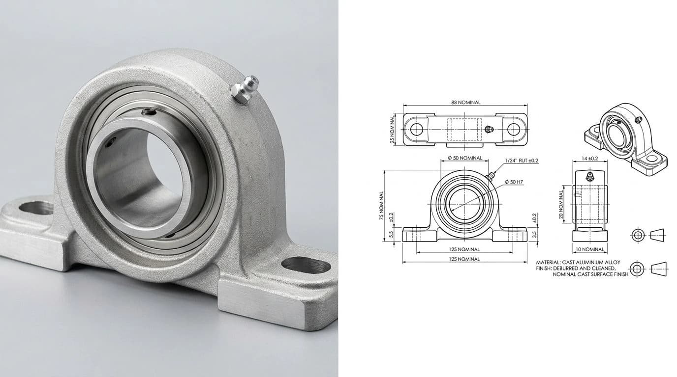
A DWG is what most people actually need at the end of an image conversion, because it is the file AutoCAD and half the drafting world treat as home. The problem is that an image and a DWG store completely different things. A picture is a grid of coloured pixels. A DWG is a database of lines, arcs, layers and dimensions with real units attached. So “image to DWG” was never a format swap like JPG to PNG. Something, a tracer, a converter, a drafter or an AI, has to rebuild the picture as geometry first. This guide walks through the three ways that happens, what a usable DWG has to contain, and the two traps, scale and version, that ruin most first attempts.
Our articles are still written by humans!
Get human written articles in your Google feed.
Convert your image to DWG right here
Open the full converter pageDrop a file here. It never leaves your browser.
PNG, JPG, WebP, GIF, BMP, HEIC, TIFF, AVIF · any size · free · DWG or DXF · works best on clean line art, logos and high contrast shapes
The short answer
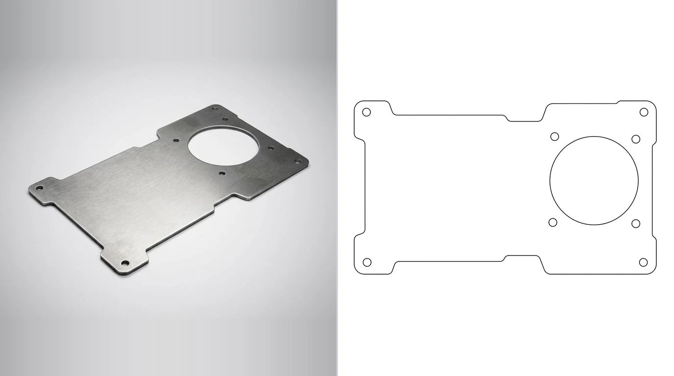
Look at your image first, because it decides everything. If it is already a drawing, a scanned blueprint, a floor plan, a logo or clean line art, then a raster-to-vector converter or a careful manual trace gets you faithful linework, and saving that as DWG is trivial. If it is a photo of a real object, a bracket in your hand, a hinge on a machine, a part you need to remake, then tracing gives you a distorted outline at a meaningless scale, and what you actually want is a tool that rebuilds the part as a dimensioned technical drawing and exports it as DWG. The broader version of this decision, across every CAD format rather than DWG specifically, lives in image to CAD: turn a JPG into a drawing you can manufacture.
What a DWG actually stores
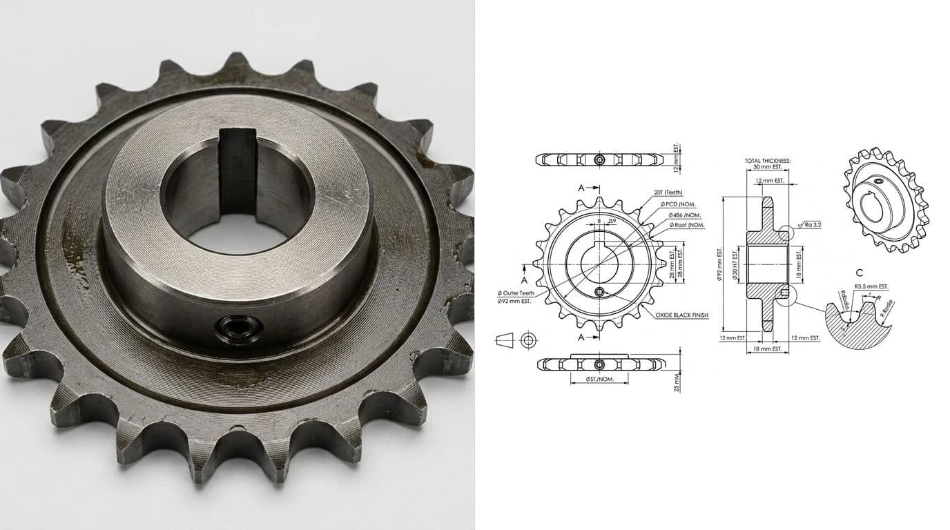
DWG is Autodesk's native drawing database, the binary format AutoCAD has saved to since 1982. Inside one file live the model space geometry, lines, polylines, arcs, circles and splines, plus layers, blocks, text styles, dimension styles, layouts and the drawing units. That last part matters most here: a DWG knows whether a line is 40 millimetres or 40 inches long. A JPG, PNG or HEIC photo knows nothing of the kind. It stores the colour of each pixel and, at best, a note about which camera took it.
That gap is why every “image to DWG converter” is really a geometry factory in disguise. Something has to decide where the edges are, turn them into lines and arcs, and pick a scale. The three routes below differ only in who does that work: you, an algorithm that follows pixels, or an AI that understands the part.
Three routes from image to DWG
1. Trace it by hand in CAD
Attach the image as an underlay in AutoCAD or any free CAD package, scale it to one known dimension, and draw over it on a fresh layer. Slowest route, cleanest result, and every line is deliberately yours. The full command-by-command walkthrough is in image to AutoCAD: convert a photo to DWG/DXF, which covers ATTACH, reference scaling and layer discipline inside AutoCAD itself.
2. Auto-vectorize, then save as DWG
Raster-to-vector software finds the edges for you and outputs linework, usually as DXF that any CAD program saves on to DWG in one step. This shines on scanned drawings, floor plans and logos, where the artwork already is the geometry. It fails quietly on photos, where it traces shadows, perspective tilt and JPG compression halos as if they were edges. If your trace comes out jagged or doubled, why a traced image looks jagged and how to fix it covers the cleanup, and the converter shootout in the best JPG to DXF converters applies one-to-one here, since DWG is one save away from DXF.
3. Rebuild it as a dimensioned drawing with AI
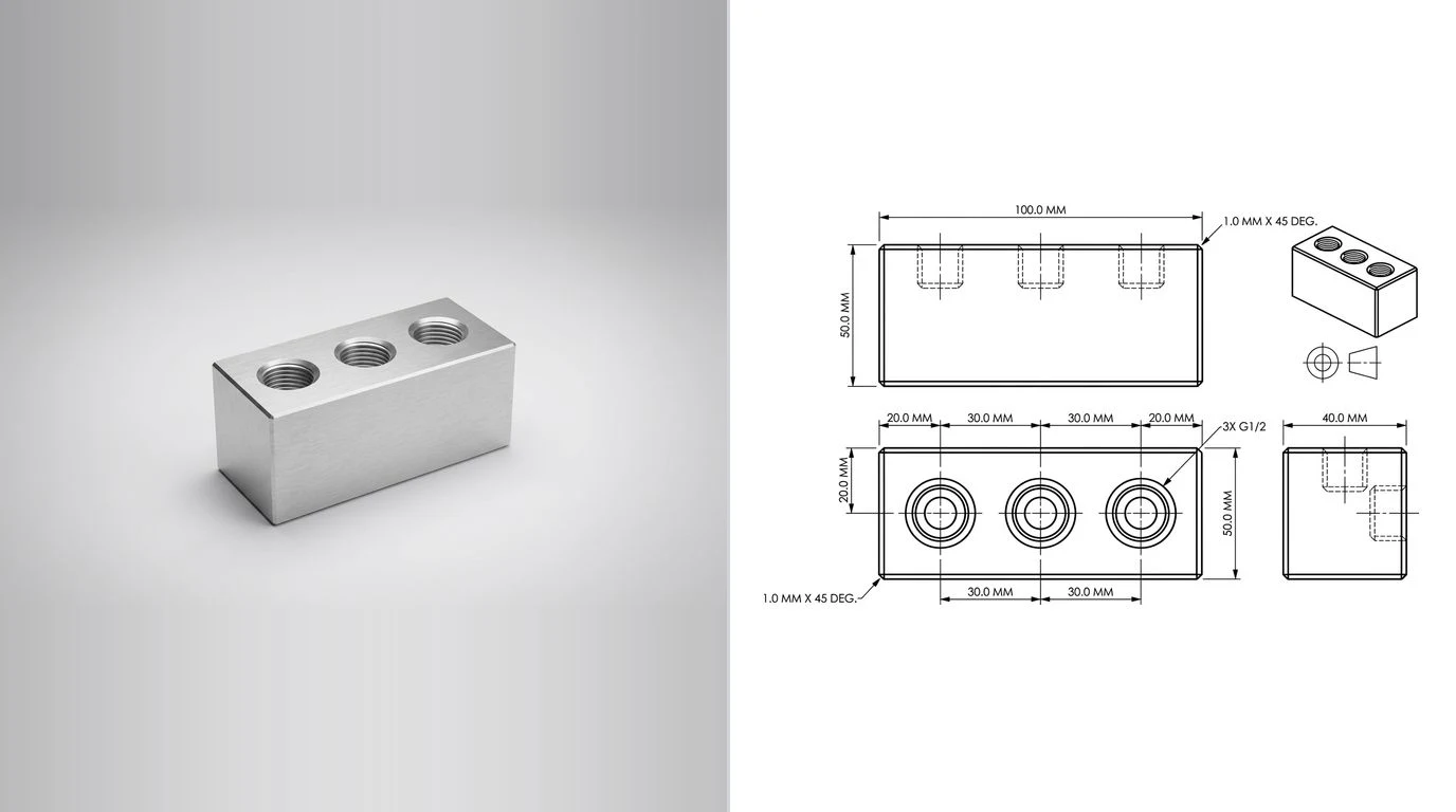
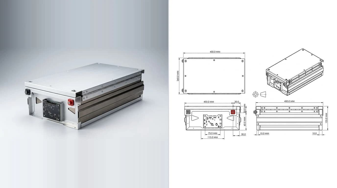
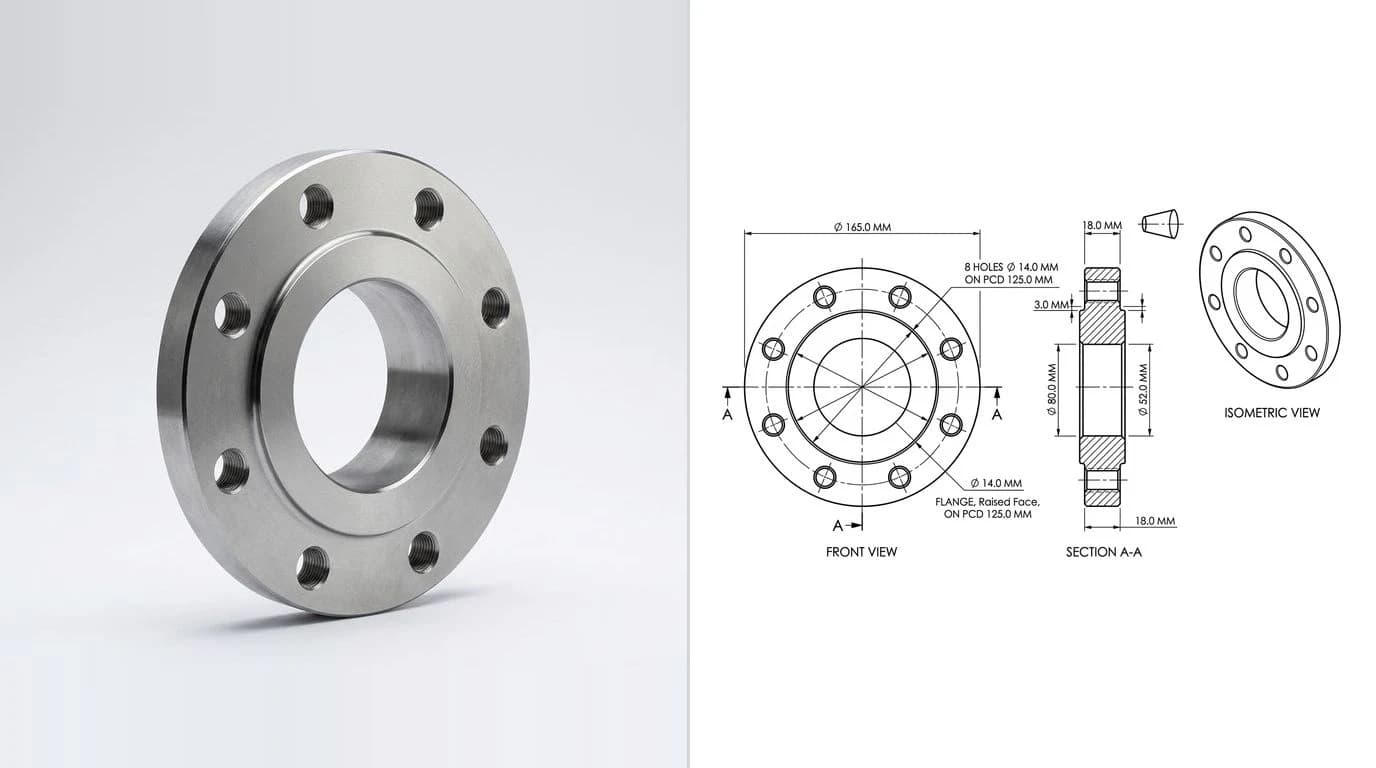
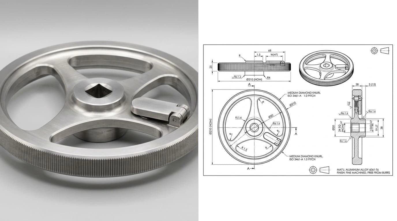
For a photo of a physical part, the first two routes stop at an outline. An AI rebuild goes the other way round: it reads the part in the photo, reconstructs proper orthographic views, dimensions them against one reference measurement you type in, and exports the result as DWG, DXF, SVG or PDF. You get a drawing with real sizes instead of a silhouette with none. That is the gap our AI technical drawing generator exists to close, and the rest of this page keeps score on where each route wins.
What a usable DWG must contain
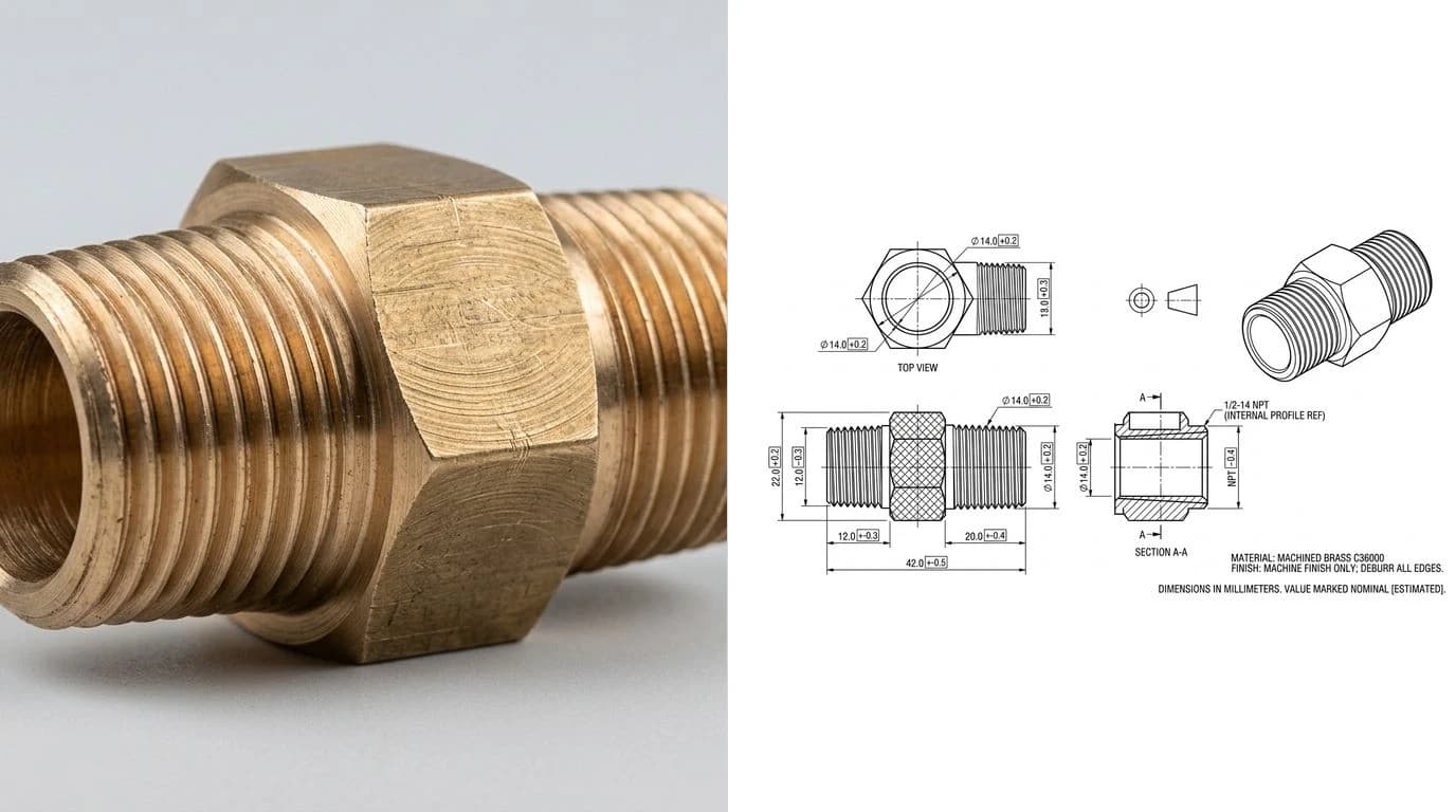
“It opens in AutoCAD” is a low bar. A DWG someone can actually edit, quote or manufacture from needs a few things a raw trace never has, and this list is what separates a conversion from a drawing:
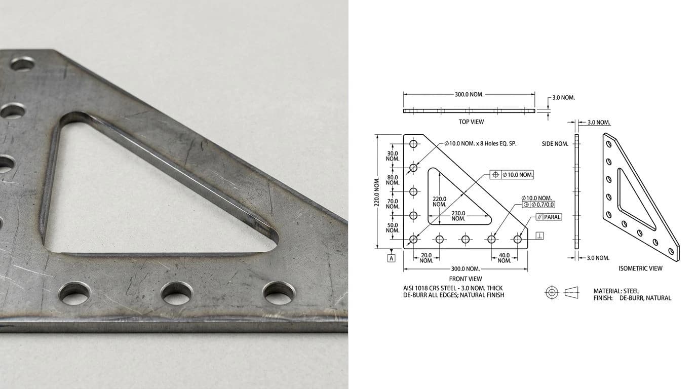
- Closed profiles. Outlines that end where they began. Open contours break hatching, offsets and any downstream CAM.
- Real units at real scale. The part measures in the file what it measures in the world. One 40 mm hole spacing that is actually 40 mm.
- Sane layers. Visible edges, dimensions and centre lines separated, so the next person can switch things off instead of deleting them.
- Dimensions as dimension objects, not exploded text and lines. Editable dimensions update when the geometry moves.
- No trace debris. No doubled lines, stray points or thousand-vertex polylines standing in for a straight edge.
What a manufacturing-ready drawing needs beyond clean geometry, notes, tolerances and a title block, is its own subject, covered in what makes a drawing manufacturing ready.
The scale problem every route shares
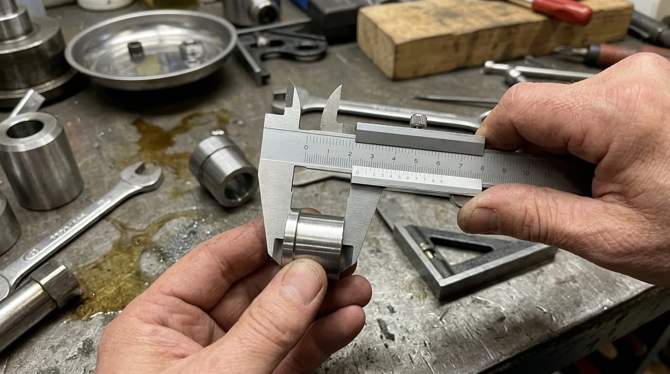
Whatever route you take, the image arrives without units, so the DWG starts life at a guess. A trace lands at whatever size the underlay happened to be. A vectorizer maps pixels to drawing units one-to-one. Both look perfectly fine on screen and both are wrong at the machine. The fix is always the same: find one dimension you know for certain, measured off the real part with calipers or printed on the original drawing, and scale everything so that one feature is right. Proportions were already correct, so every other size follows.
AI rebuilds bake this in up front by asking for the reference measurement before drawing anything, which is why their output carries dimensions and traced output cannot. The idea in depth, including how to pick a trustworthy reference feature, is in how to get dimensions from a photo, and the classic failure it prevents is dissected in fixing a drawing that imports at the wrong size.
The DWG version trap
DWG is not one format, it is a family of release formats that changes every few years, and compatibility only runs backwards. AutoCAD 2026 happily opens a 2013 DWG. AutoCAD 2018 refuses a 2026 one. Every “the file won't open” email between collaborators has this asymmetry somewhere near the bottom of it. Because non-Autodesk software reads and writes DWG through reverse-engineered libraries, an older release format is also the one they handle most reliably.
Should you even ask for DWG?
Sometimes the honest answer to “how do I convert this image to DWG” is that you want a DXF instead. The two formats describe the same 2D geometry, and the difference is destination. DWG is native to AutoCAD and stays the right call when the file is going back into a drafting seat for further editing. DXF is the exchange format that laser, plasma and CNC software reads almost universally, so a file headed to a shop travels better as DXF. A good converter or AI tool exports both from the same drawing, which turns the question into a checkbox instead of a second conversion.
The full comparison is in DWG vs DXF, the cutter-side conversion runs in our image to DXF converter, and the wider map of which format each machine wants is in CAD file formats for manufacturing.
If your source is already one particular kind of file, the same DWG converter has a page built around it: a JPEG, a photo or a picture all run through the same trace and land on the same DWG.
Tools compared
Image to DWG, by route and tool
For artwork that is already a drawing, the tracers genuinely do the job, and paying mostly buys convenience. The photo-of-a-part case is the one none of them solve, because it is not a tracing problem. It is a drafting problem, and the honest comparison for that case is against hiring a drafter, which what a technical drawing costs prices out. If your source is a phone snapshot rather than a studio shot, JPG to CAD covers the extra cleanup a compressed photo needs.
Checklist before you send it
- Right route for the image? Drawing traced, photo rebuilt. Mixing those up wastes every step after.
- Scale anchored to a known measurement? Verify one feature with calipers or the original print, never assume.
- Profiles closed and debris deleted? Offset a contour as a test; if it breaks, the profile is open.
- Saved to an older DWG release format? 2013 or 2018 for anything leaving your machine.
- Recipient actually wants DWG? Shops usually prefer DXF; drafters prefer DWG. Ask once, export the right one.
Clear those five and your “converted image” is a real drawing. If the part is headed for a quote, the last mile, notes, tolerances and everything a shop reads before pricing, is in from photo to a manufacturing drawing.
Frequently asked questions
How do I convert an image to a DWG file?
There are three working routes. Trace the image by hand inside a CAD program and save as DWG. Run it through a raster-to-vector converter, which outputs DXF or DWG linework automatically. Or, for a photo of a real part, use an AI tool that rebuilds the object as a dimensioned technical drawing and exports DWG directly. Which route fits depends on whether your image is already a drawing or a photo of a physical thing.
Can I convert a JPG to DWG for free?
Yes, with limits. Free web converters and Inkscape can vectorize a clean, high-contrast JPG and get you DXF or DWG linework. The catch is quality: JPG compression halos become fake geometry, the output arrives at an arbitrary pixel scale, and nothing free adds dimensions. For a logo or a clean scanned drawing that is often good enough. For a part you need to manufacture, it usually is not.
Is there an AI that converts an image to DWG?
Yes. AI tools like TechDraw AI take a photo of a real object, rebuild it as a proper 2D technical drawing with orthographic views and dimensions tied to one reference measurement you provide, and export DWG, DXF, SVG or PDF. That is different from a tracer, which only copies the visible outline at pixel scale with no dimensions.
Does converting an image to DWG give me real dimensions?
Not by itself. A raster image stores pixels, not millimetres, so no converter can recover a size that was never in the file. Tracing and auto-vectorizing both deliver unscaled linework. To get real dimensions you either scale the result to one known measurement afterwards, or use a tool that rebuilds the drawing around a reference measurement from the start.
What DWG version should I save or export?
When in doubt, pick an older release format like AutoCAD 2013 or 2018 DWG. DWG is backwards compatible, meaning new software opens old files, but not forwards compatible, so a file saved in the newest format may refuse to open in an older seat of AutoCAD or a viewer. Most export dialogs let you choose the version; older is the safer handoff.
Should I convert my image to DWG or DXF?
DWG if the file is going back into AutoCAD or another Autodesk product, because it is the native format and keeps the most fidelity. DXF if it is going to a laser, plasma or CNC shop, because cutting software reads DXF almost universally. Good tools export both from the same drawing, so this is a handoff decision, not a conversion quality decision.