Drawing Symbol Finder
Paste anything you cannot read off a drawing: a symbol, a fit like 13 g5, a finish like Ra 3.2. You get the one-line answer plus the real numbers.
ISO 286 fit
13 g5 is a shaft: 12.986 to 12.994 mm
- Reads as
- 13 mm nominal, deviation letter g, tolerance grade IT5
- Feature
- A shaft, because the letter is lower case
- Upper deviation
- -0.006 mm
- Lower deviation
- -0.014 mm
- Limits
- 12.986 to 12.994 mm
- Tolerance band
- 8 µm
Lower case is a shaft. An upper-case letter at the same size and grade would be a hole with different numbers.
Read the whole notation on how to read tolerances on a drawing.
Or find it by eye
Size and dimension
Geometric tolerance (GD&T)
Modifiers and qualifiers
Surface texture

Built and checked by Branislav Hrivnák, Co-Founder, TechDraw AI. Last checked September 2026.
What the answers here come from
- ASME Y14.5-2018, Dimensioning and Tolerancing for the 14 geometric characteristics, the modifiers, and the basic and reference dimension rules.
- ISO 1101, Geometrical product specifications: geometrical tolerancing for the ISO side of the same symbols, including the two ASME removed in 2018.
- ISO 286-1 and ISO 286-2, ISO code system for tolerances on linear sizes for every IT grade and fundamental deviation the fit calculator returns.
- ISO 21920-1, Surface texture: profile for the surface texture symbol, where the process and the lay are written, and the Ra and Rz parameters.
- ISO 129-1, Technical drawings: indication of dimensions and tolerances for the dimension symbols and how they sit against the value.
The fit limits are not typed in. They are computed from the ISO 286 grade and deviation tables on every render, and 62 assertions check them against published values on every change, including the delta rule that makes a 25 mm K7 hole +0.006/−0.015 rather than the −0.002/−0.023 you get by mirroring the shaft. The surface finish rows come from the same module as the conversion chart, so the two pages cannot disagree.
Four callouts and what they mean
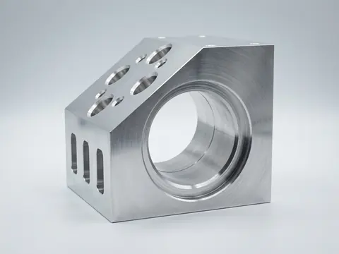
The part on the left, what its callout resolves to on the right. Every symbol and every millimetre on a right-hand card is drawn by the same modules the box above runs, so a card cannot show a limit the tool would not return.
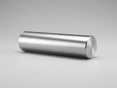
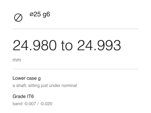
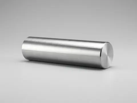
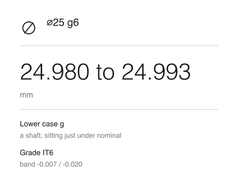
⌀25 g6 is 24.980 to 24.993 mm
Lower case, so a shaft. It sits just under nominal, on purpose.
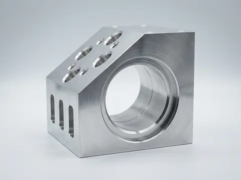
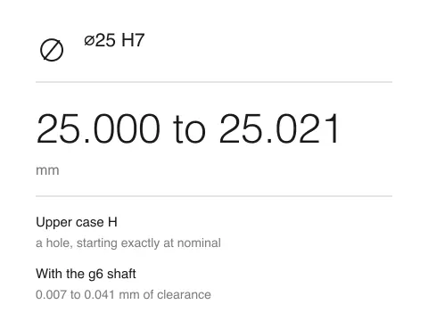
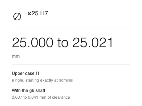
⌀25 H7 is 25.000 to 25.021 mm
Upper case, so a hole. With the g6 shaft: 0.007 to 0.041 clearance.
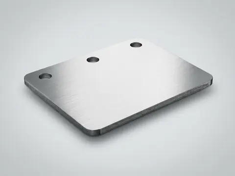
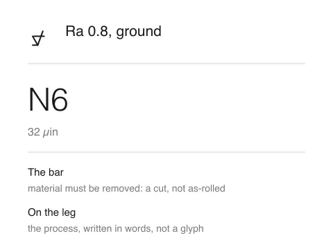
Ra 0.8, ground is N6, 32 µin
The bar means a cut is required. The process is written, not drawn.
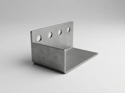
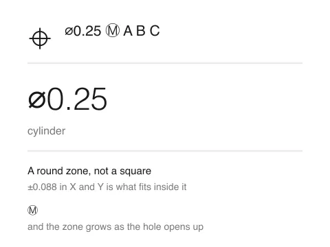
⌀0.25 Ⓜ A B C is a 0.25 cylinder
A round zone. The biggest square that fits inside it is only ±0.088.
Trusted by


What it will not answer
- Welding symbols and thread callouts. Both are notations of their own size and neither is in the catalogue. The tool says so rather than returning the nearest thing it has.
- ISO 286 classes a, b, c and t to zc, and the bare shaft j. They are real classes, but they are tabulated in sub-ranges this tool does not model, so it refuses them by name and tells you to read a full ISO 286-2 table. Twelve classes are covered: d, e, f, g, h, js, k, m, n, p, r and s, in both cases, which is nearly everything a drawing actually uses.
- Rz from an Ra. There is no conversion. They measure different things, and two surfaces with the same Ra can have very different Rz. The tool shows a planning estimate of roughly four times Ra and labels it as an estimate every time.
- A symbol your company invented. Critical-dimension flags, key characteristics and inspection balloons are not standardised. If you are looking at one, its meaning is in the drawing's own notes and nowhere else.
Copy a symbol
Tap one to put the character on your clipboard. The page draws every symbol rather than typing it, because a third of them have no reliable font support. What you paste has to be the real code point, so those are two different things here on purpose.
These are characters, not pictures, so they paste into a CAD annotation, an email or a spreadsheet. Seven of the thirty-nine symbols on this page are missing here on purpose. The surface texture family and the basic dimension box have no Unicode character, and the usual stand-ins mean something else. Where a character is only an approximation the tool says so on the symbol itself.
All 39 symbols and what each one means
The same entries the box above searches, in full, with the standard clause each comes from. Where this site has a proper treatment of a family, the link is on the entry.
Size and dimension
- Diameter
A circle with a slash through it means diameter: the dimension after it is measured across the full circle, not the radius.
It goes in front of the number, so ⌀12 is a twelve millimetre hole or shaft. It is a slashed circle and not the letter O or a zero. The slash leans at about 75 degrees. On older or US drawings you will also see DIA written out after the number instead.
⌀12 means twelve millimetres across the circle.
⌀ U+2300 DIAMETER SIGN · ISO 129-1; ASME Y14.5-2018 §3.3.7 · Every dimension symbol, in order
- Radius
R before a number means radius: the dimension is from the centre of the arc to its edge, so the full round is twice that.
R6 is a six millimetre radius, which is a twelve millimetre full round. The leader arrow touches the arc and points at its centre. CR means a controlled radius, which is stricter: the arc has to be a fair curve inside the tolerance band with no flats or reversals, not merely land within it.
R6 means a six millimetre radius, ⌀12 if it were a full circle.
R U+0052 LATIN CAPITAL LETTER R · ISO 129-1; ASME Y14.5-2018 §3.3.9 · Every dimension symbol, in order
- Spherical diameter and radius
S⌀ and SR mean the feature is a sphere, not a cylinder or an arc in one plane.
Without the S, a ⌀ on a rounded end is ambiguous: it could be a cylinder seen end-on. S⌀20 is unambiguously a twenty millimetre ball. SR is the same idea for a partial sphere, such as a dished seat.
S⌀20 means a twenty millimetre sphere.
S⌀ U+0053 U+2300 LATIN CAPITAL LETTER S + DIAMETER SIGN · ASME Y14.5-2018 §3.3.10
- Square
A small square before a number says the section is square, so one dimension covers both sides.
□25 is a 25 by 25 section, dimensioned once instead of twice. It saves a dimension and removes the chance of the two being toleranced differently by mistake.
□25 means a 25 by 25 mm square section.
□ U+25A1 WHITE SQUARE, a substitute · ISO 129-1; ASME Y14.5-2018 §3.3.11
- Depth
The downward arrow with a bar means depth: how far the hole or pocket goes, measured from the surface it starts on.
It follows the size, so ⌀8 ↧20 is an eight millimetre hole twenty deep. For a drilled hole the depth is to the full diameter, not to the tip of the drill point, unless the drawing says otherwise. Older drawings write DP or DEEP instead.
⌀8 ↧20 means an ⌀8 hole, 20 mm deep.
↧ U+21A7 DOWNWARDS ARROW FROM BAR, a substitute · ASME Y14.5-2018 §3.3.13 · Every dimension symbol, in order
- Counterbore and spotface
The flat-bottomed bracket means counterbore: a wider flat-bottomed hole on top of the through hole, so a cap screw head sits below the surface.
It reads as a stack: the through hole first, then the counterbore diameter and its depth. SF on the same symbol means spotface, which is the same cut taken shallow, just enough to give a washer or a bolt head a flat seat on a rough or angled surface.
⌀6.6 ⌴⌀11 ↧6.5 means a 6.6 clearance hole with an 11 mm counterbore 6.5 deep, for an M6 cap screw.
⌴ U+2334 COUNTERBORE · ASME Y14.5-2018 §3.3.12
- Countersink
The open V means countersink: a cone cut into the mouth of the hole so a flat-head screw finishes flush.
It carries two numbers, the diameter at the surface and the included angle: ⌵⌀11 × 90°. The angle is the full included angle of the cone, not the half angle, and it has to match the screw head or the head will not seat.
⌵⌀11 × 90° means an 11 mm countersink at 90 degrees included.
⌵ U+2335 COUNTERSINK · ASME Y14.5-2018 §3.3.12
- Slope and taper
The flat wedge means slope, the ratio of rise to run of one surface; the symmetrical wedge next to it means taper, the change in diameter along a length.
Both are written as a ratio: ⌳1:20 is a slope that rises one for every twenty along. The point of the wedge always aims the same way the feature narrows, which is how you tell which end is the big one. Taper applies to a cone, slope to a single inclined face.
⌳1:20 means a face that rises 1 mm for every 20 mm along.
⌳ U+2333 SLOPE · ISO 129-1
- Thickness
A lower-case t before a number is thickness, used on sheet and plate parts where the third dimension is not drawn.
t3 on a flat pattern means three millimetre material. It exists because a sheet metal part is drawn as one flat view and there is nowhere to put a thickness dimension. THK is the same thing written out, and the material callout in the title block should agree with it.
t3 means three millimetre sheet.
t U+0074 LATIN SMALL LETTER T · ISO 129-1
- Reference dimension
A dimension in round brackets is a reference: it is shown for convenience and carries no tolerance, so nobody inspects it.
(75) is repeating information the drawing already fixes somewhere else, usually an overall length that falls out of the dimensions above it. Never machine to a reference dimension and never argue a part is out of spec because one is off. The dimensions that build it are the ones that count. REF written after a number means the same thing.
(75) means 75 mm, shown for information only, not inspected.
() U+0028 U+0029 LEFT and RIGHT PARENTHESIS · ASME Y14.5-2018 §3.3.4
- Basic dimension
A dimension in a rectangular box is basic: an exact theoretical value with no tolerance of its own, because a geometric tolerance elsewhere controls it.
It is the opposite of a reference dimension. A boxed 40 locating a hole is not sloppy, it is exact by definition, and the position tolerance in the feature control frame is what allows the hole to be off it. If you see a boxed dimension there is always a geometric tolerance somewhere doing the toleranting.
a boxed 40 means exactly 40 mm in theory; a position tolerance says how far off it may really be.
No Unicode character · ASME Y14.5-2018 §3.3.3; ISO 1101 · How basic dimensions work with GD&T
- Critical and key characteristic
There is no single standard symbol for a critical dimension: a flagged triangle, a circled number or a diamond, whichever the drawing's own notes define.
This is the honest answer to a question people expect a chart entry for. ASME Y14.5 does not define one, so companies invent their own and explain it in the title block or a general note. If you are looking at a flag you do not recognise, the definition is somewhere on the sheet. It is not something you can look up.
No Unicode character · Not standardised; defined per drawing
- Number of features
An X after a count means how many identical features share the callout, so 4× ⌀6 is four six millimetre holes, not one.
It saves repeating the same dimension on every hole in a pattern. Watch which way round it sits: 4× ⌀6 is a count, while ⌀11 × 90° in a countersink callout is an angle. The count always comes first with the X on its right.
4× ⌀6 means four holes, each six millimetres.
× U+00D7 MULTIPLICATION SIGN · ASME Y14.5-2018 §3.3.6
- Plus-minus tolerance
± gives a symmetric tolerance band: 25 ±0.1 may measure anywhere from 24.9 to 25.1.
When the two halves are not equal they are written stacked instead, one above the other with their own signs. If a dimension has no tolerance at all, the general tolerance in the title block applies, usually a class of ISO 2768 or a table of values by decimal place.
25 ±0.1 means 24.9 to 25.1 mm.
± U+00B1 PLUS-MINUS SIGN · ISO 129-1; ISO 2768 for general tolerances · Reading every tolerance on a drawing
Geometric tolerance (GD&T)
- Straightness
Straightness holds a line element of the surface, or the axis, between two parallel straight lines that far apart.
It is a form control, so it needs no datum. Applied to a surface it controls each line element on its own; applied to the axis, with a ⌀ in the frame, it controls the whole centreline as a cylinder of tolerance.
⏤ U+23E4 STRAIGHTNESS · ASME Y14.5-2018 §5.4.1; ISO 1101
- Flatness
Flatness holds the whole surface between two parallel planes that far apart, with no datum involved.
The parallelogram is the symbol. Because it needs no datum, the surface can sit at any angle to everything else and still pass, because it only has to be flat in itself. That is the difference between flatness and parallelism, which people mix up constantly.
⏥ U+23E5 FLATNESS · ASME Y14.5-2018 §5.4.2; ISO 1101
- Circularity (roundness)
Circularity holds each cross-section between two concentric circles that far apart in radius.
It is measured slice by slice, so a banana-shaped shaft can be perfectly circular everywhere along it. Controlling the whole cylinder at once is cylindricity, not this.
○ U+25CB WHITE CIRCLE, a substitute · ASME Y14.5-2018 §5.4.3; ISO 1101
- Cylindricity
Cylindricity holds the whole cylindrical surface between two coaxial cylinders that far apart in radius.
It is circularity, straightness and taper controlled in one go, which makes it the most expensive form control on the sheet. Specify it only where the function needs the whole surface, such as a bearing journal.
⌭ U+232D CYLINDRICITY · ASME Y14.5-2018 §5.4.4; ISO 1101
- Profile of a line
Profile of a line holds each cross-section of a contour inside a two-dimensional tolerance band that follows the true shape.
The half circle sitting on a line is the symbol. It works on any shape, which is why profile controls are the general-purpose tool of GD&T. A single profile callout can replace a page of plus-minus dimensions on a moulded or cast form.
⌒ U+2312 ARC · ASME Y14.5-2018 §11; ISO 1101
- Profile of a surface
Profile of a surface holds the whole surface inside a three-dimensional band that follows the true shape.
The closed circle is the symbol. Unless the frame says otherwise the band is equal on both sides of the true profile; a Ⓤ in the frame moves it, so the material can be biased one way.
⌓ U+2313 SEGMENT · ASME Y14.5-2018 §11; ISO 1101
- Angularity
Angularity holds a surface or axis between two parallel planes at a stated angle to a datum.
The angle itself is a basic dimension in a box; angularity tolerances how far the surface may wander from it. At 90 degrees you would use perpendicularity instead, and at 0 degrees parallelism, because they are the same control at fixed angles.
∠ U+2220 ANGLE · ASME Y14.5-2018 §10.4.3; ISO 1101
- Perpendicularity
Perpendicularity holds a surface or axis square to a datum, inside a band that far apart.
It always names a datum, because square to nothing means nothing. With a ⌀ in front of the tolerance it controls an axis inside a cylinder of tolerance rather than a surface between two planes.
⟂ U+27C2 PERPENDICULAR · ASME Y14.5-2018 §10.4.2; ISO 1101
- Parallelism
Parallelism holds a surface or axis parallel to a datum, inside a band that far apart.
The difference from flatness is the datum: a parallelism callout compares the surface to something else, flatness compares it only to itself. A surface can be dead flat and badly out of parallel at the same time.
∥ U+2225 PARALLEL TO · ASME Y14.5-2018 §10.4.1; ISO 1101
- Position (true position)
Position is the crossed circle: it holds a feature's axis or centre plane inside a tolerance zone centred on where basic dimensions say it should be.
This is the most used symbol in GD&T and the one most often mistaken for the diameter sign. With ⌀ before the tolerance the zone is a cylinder rather than two pairs of planes, and that is the whole reason to convert: ±0.25 in X and Y is a 0.5 mm square whose corners already sit 0.354 mm off centre, so the round zone that just contains it is ⌀0.707, which is 57 percent more area for exactly the same worst case.
⌀0.25 Ⓜ A B C means the axis must lie in a 0.25 cylinder at the basic location, with bonus tolerance at MMC, relative to datums A, B and C.
⌖ U+2316 POSITION INDICATOR · ASME Y14.5-2018 §10.3; ISO 1101 · The full feature control frame, read left to right
- Concentricity
Concentricity, two circles one inside the other, holds the median points of a feature about a datum axis, and it was removed from ASME Y14.5 in 2018.
It survives on older drawings and in ISO 1101, but it is hard to measure and almost always the wrong tool. What people usually mean is runout, which measures the surface rather than derived median points, or position applied to the axis. If you are writing a drawing today, use one of those.
◎ U+25CE BULLSEYE, a substitute · ISO 1101; removed from ASME Y14.5-2018
- Symmetry
Symmetry holds the median points of a feature about a datum centre plane, and like concentricity it was removed from ASME Y14.5 in 2018.
The same objection applies: it is defined on derived points that no gauge touches. Position applied to the centre plane does the same job and is checkable.
⌯ U+232F SYMMETRY · ISO 1101; removed from ASME Y14.5-2018
- Circular runout
Circular runout is the total indicator movement at one cross-section while the part turns a full revolution about a datum axis.
The single arrow is the symbol. Because it is measured one slice at a time it catches out-of-round and off-centre together, but not taper along the length. It is cheap to check: an indicator, a pair of centres and a turn by hand.
↗ U+2197 NORTH EAST ARROW, a substitute · ASME Y14.5-2018 §12; ISO 1101
- Total runout
Total runout is the indicator movement over the whole surface at once as the part turns, so it catches taper and lobing as well as eccentricity.
The double arrow is the symbol. The indicator traverses along the feature while the part rotates, and every reading has to fall inside one band. It is the strictest of the runout controls and the closest thing to cylindricity referenced to a datum.
⌰ U+2330 TOTAL RUNOUT · ASME Y14.5-2018 §12; ISO 1101
Modifiers and qualifiers
- Maximum material condition (Ⓜ)
Ⓜ after a tolerance means the stated value applies at maximum material condition, and the feature earns extra tolerance as it departs from it.
Maximum material is the heaviest the part can legally be: the largest shaft, the smallest hole. A ⌀8.0 to ⌀8.2 hole with position ⌀0.2 Ⓜ gets ⌀0.2 at 8.0 and ⌀0.4 at 8.2. That extra is called bonus tolerance and it is free, because a bigger hole still assembles.
⌀0.2 Ⓜ A B C means 0.2 at MMC, growing to 0.4 as the hole opens up to its upper limit.
Ⓜ U+24C2 CIRCLED LATIN CAPITAL LETTER M · ASME Y14.5-2018 §7.3.2
- Least material condition (Ⓛ)
Ⓛ means the tolerance applies at least material condition, the lightest the part can legally be.
It is the mirror of Ⓜ and far rarer. It protects wall thickness and edge distance rather than assembly: the case where a hole drifting off location while it is at its largest would break out of the side.
Ⓛ U+24C1 CIRCLED LATIN CAPITAL LETTER L · ASME Y14.5-2018 §7.3.3
- Projected tolerance zone (Ⓟ)
Ⓟ projects the tolerance zone out of the part, into the space a stud or a dowel will occupy.
It matters for threaded and press-fit holes, because what actually has to line up is the fastener sticking out, not the hole in the plate. Ⓟ25 means the zone extends 25 mm above the surface. Without it a slightly tilted tapped hole passes and the assembly still will not go together.
⌀0.2 Ⓜ Ⓟ25 A means the zone is projected 25 mm out of the face, where the stud lives.
Ⓟ U+24C5 CIRCLED LATIN CAPITAL LETTER P · ASME Y14.5-2018 §10.3.4
- Free state (Ⓕ) and tangent plane (Ⓣ)
Ⓕ means measure the feature unclamped, as it sits; Ⓣ means judge the tolerance against a plane laid on the high spots rather than the surface itself.
Ⓕ appears on thin, flexible and non-rigid parts, where the drawing otherwise assumes the part is restrained. Ⓣ loosens a surface control to what a mating flat face would actually feel, which is often all the function needs.
ⒻⓉ U+24BB U+24C9 CIRCLED LATIN CAPITAL LETTER F + T · ASME Y14.5-2018 §7.3.4 and §7.4
- Diameter inside a feature control frame
A ⌀ in front of the tolerance value inside a feature control frame makes the tolerance zone a cylinder rather than two parallel planes.
This is the other place the diameter sign turns up and it does something different from the one in a dimension. ⌀0.5 in a position frame means the axis may be anywhere inside a 0.5 mm cylinder, a round zone in every direction, which is why it is not the same as ±0.25 in each axis.
⌖ ⌀0.5 A B C means the axis lies within a 0.5 mm diameter cylinder about the basic location.
⌀ U+2300 DIAMETER SIGN · ASME Y14.5-2018 §10.3.1
- All around and all over
A circle on the kink of the leader means the control applies all around the profile in that view; a double circle means all over the whole part.
Without one of these a profile tolerance stops at the ends of the contour the leader points to. With all around, it wraps the outline of that view. All over is the three-dimensional version and covers every surface of the part.
⌮ U+232E ALL AROUND-PROFILE · ASME Y14.5-2018 §11.3
Surface texture
- Surface texture symbol
The bare tick is the basic surface texture symbol: it says a finish is specified here, and on its own it says nothing about how the surface is made.
Two legs meeting at a point on the surface, the right leg longer. Everything else hangs off it in fixed positions: the roughness value, then the process, then the lay. It is never used bare on a modern drawing; it always carries a value or a bar.
No Unicode character · ISO 21920-1 (replaced ISO 1302) · Every surface finish symbol in use
- Material removal required
A horizontal bar across the tick means material must be removed: the surface has to be machined, ground or otherwise cut.
This is the symbol most people mean when they say the machining symbol. The bar is a requirement, not a suggestion. An as-cast or as-rolled surface that happens to meet the roughness number still fails, because the drawing demanded a cut.
No Unicode character · ISO 21920-1 §7 · Every surface finish symbol in use
- Material removal prohibited
A circle in the crook of the tick means material must not be removed: the surface has to stay as it came from casting, forging, rolling or moulding.
It protects a skin that matters: a cast draft face, a rolled surface, an injection-moulded finish. Machining it, even to make it better, is a rejection.
No Unicode character · ISO 21920-1 §7 · Every surface finish symbol in use
- Grinding (and every other process)
There is no grinding symbol as such. Grinding is required by writing the word on the long leg of the surface texture symbol, above the bar.
This trips people up because charts imply every process has a glyph. They do not. The long upper leg is a labelled line: you write ground, milled, turned, honed, lapped or anything else along it, in words, and it becomes a manufacturing requirement rather than a suggestion. What the symbol carries as a glyph is only whether material must be removed, plus the roughness value and the lay.
a tick with a bar, Ra 0.8 under it, and "ground" written on the upper leg means grind this surface to Ra 0.8 µm.
No Unicode character · ISO 21920-1 §7.4 · Every surface finish symbol in use
- Lay direction
The small mark to the right of the tick is the lay: which way the tool marks run.
= is parallel to the view, ⊥ perpendicular, X crossed, M multidirectional, C circular, R radial and P particulate or non-directional. It matters wherever a seal slides or a joint has to hold, because a surface at the same Ra leaks differently depending on which way the scratches point.
No Unicode character · ISO 21920-1 §7.5 · Every surface finish symbol in use
Reading a fit callout
A callout like 13 g5 is three pieces of information stacked together: the nominal size, a letter that says where the tolerance band sits relative to that size, and a number that says how wide the band is. Case is the whole difference between a hole and a shaft.
| Callout | Feature | Upper | Lower | Limits (mm) |
|---|---|---|---|---|
| 13 g5 | shaft | -0.006 | -0.014 | 12.986 to 12.994 |
| 25 H7 | hole | +0.021 | 0 | 25.000 to 25.021 |
| 25 h6 | shaft | 0 | -0.013 | 24.987 to 25.000 |
| 25 g6 | shaft | -0.007 | -0.020 | 24.980 to 24.993 |
| 25 k6 | shaft | +0.015 | +0.002 | 25.002 to 25.015 |
| 25 p6 | shaft | +0.035 | +0.022 | 25.022 to 25.035 |
| 50 H8 | hole | +0.039 | 0 | 50.000 to 50.039 |
| 50 f7 | shaft | -0.025 | -0.050 | 49.950 to 49.975 |
Every row is computed from the ISO 286 tables at build time, not transcribed, so it cannot disagree with the box at the top of the page. The IT grade sets the width alone: IT7 is 21 µm at 25 mm and 35 µm at 100 mm, because the standard widens the band as the part grows. The full treatment of tolerances is here.
Reading a finish value
The number under a surface texture symbol is almost always Ra, in micrometres on a metric drawing and microinches on a US one. The N-grades are just names for standard Ra values.
| Grade | Ra µm | Ra µin | Typically |
|---|---|---|---|
| N1 | 0.025 | 1 | Lapped, mirror |
| N2 | 0.05 | 2 | Superfinished |
| N3 | 0.1 | 4 | Honed, lapped |
| N4 | 0.2 | 8 | Fine ground |
| N5 | 0.4 | 16 | Ground |
| N6 | 0.8 | 32 | Fine turned or ground |
| N7 | 1.6 | 63 | Smooth machined |
| N8 | 3.2 | 125 | General machined |
| N9 | 6.3 | 250 | Rough machined |
| N10 | 12.5 | 500 | Coarse, as-cast |
| N11 | 25 | 1000 | Sand cast, flame cut |
| N12 | 50 | 2000 | Very rough |
Ra in micrometres and microinches is an exact unit conversion. RMS and Rz are not: RMS runs about 11 percent above Ra, and Rz cannot be converted from Ra at all. The full chart, with RMS and the Rz estimate.
Where to read the whole topic
GD&T symbols, all 14
The geometric characteristics in depth: feature control frames, datums, modifiers, and how the whole notation fits together.
Dimension symbols
Diameter, radius, counterbore, countersink, depth and the rest, with how each one sits against its value.
Surface finish symbols
The texture symbol in full: every position on it, the lay symbols, and what a process written on the leg commits you to.
Reading tolerances
Plus-minus, limit dimensions, ISO 2768 general tolerances, and what a fit callout means for the part in your hand.
Reading a drawing, start to finish
Views, scale, the title block and the order to read a sheet in, for anyone who is not sure where to begin.
Surface finish conversion chart
Ra, Rz, RMS, microinches and N-grades side by side, with the Ra each machining process actually gives.
Questions people actually search
- What does a circle with a line through it mean on a drawing?
- It is one of two different things and the difference matters. In a dimension, a circle with a slash leaning through it is the diameter symbol: ⌀12 is a twelve millimetre hole or shaft. Inside a rectangular feature control frame, a circle with a full vertical and horizontal cross through it is the position symbol, which controls where a feature sits relative to its datums. The diameter sign has one leaning slash; the position sign has a cross that extends past the circle on all four sides.
- What does 13 g5 mean on a drawing?
- It is an ISO 286 fit callout for a shaft. 13 is the nominal size in millimetres, g is the fundamental deviation letter, which sets where the tolerance band sits relative to nominal, and 5 is the IT grade, which sets how wide the band is. At 13 mm, g gives an upper deviation of -0.006 mm and IT5 is 0.008 mm wide, so the shaft must measure between 12.986 and 12.994 mm. The letter being lower case is what makes it a shaft; an upper-case G would be a hole with different numbers.
- What is the grinding symbol on an engineering drawing?
- There is not one. Grinding is not a glyph. It is required by writing the word on the long upper leg of the surface texture symbol. The symbol itself only carries whether material must be removed, which is the horizontal bar across the tick, plus the roughness value and the lay direction. Any process can go on that leg: ground, milled, turned, honed, lapped. Charts that show a dedicated grinding symbol are showing you the material-removal-required symbol with a process written on it.
- Why is a dimension in brackets on a drawing?
- Round brackets make it a reference dimension: it is shown for convenience and carries no tolerance, so it is never inspected and never machined to. It is normally information the drawing already fixes elsewhere, such as an overall length that falls out of the dimensions above it. A dimension in a rectangular box is the opposite: a basic dimension, an exact theoretical value that a geometric tolerance elsewhere on the sheet controls.
- Does this tool cover weld symbols and thread callouts?
- Not yet. It covers 39 symbols across four families: dimension and size symbols, the 14 geometric characteristics of GD&T, the modifiers that go inside a feature control frame, and the surface texture symbols. Welding symbols are a large notation of their own and thread callouts are a separate system again, so rather than half-cover them the tool says so when you search for one.
- Is a hole H7 or h7?
- Upper case is always a hole and lower case is always a shaft. That single convention carries a lot of meaning: at 25 mm, H7 runs from 25.000 to 25.021 while h7 runs from 24.979 to 25.000. Same size, same grade, and the two bands do not overlap except at nominal. If a drawing gives you a letter and you cannot tell the case from the print quality, the context usually can, because a bore is a hole and a shaft diameter is a shaft.
Or skip reading the drawing and make one
If you are decoding somebody else's sheet because you need your own, TechDraw AI goes the other way: a photograph of a part and one reference measurement in, a dimensioned drawing out, exported as DWG, DXF, SVG or PDF.
Try it on a photo