
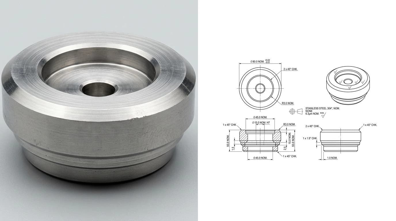
Most of the confusion on a technical drawing is not the geometry. It is the shorthand wrapped around the numbers: a Ø here, an SR there, a bracket-shaped squiggle in a hole note, a 2 x 45° floating by an edge. Each one is a precise instruction with a standard meaning, and there are fewer of them than you would think. This page covers the dimension symbols, the ones that describe size and shape. They are the alphabet you need before the heavier grammar of GD&T, which our engineering drawing symbols and GD&T guide handles separately.
Our articles are still written by humans!
Get human written articles in your Google feed.


The quick chart
Bookmark version first, details after. These are the symbols that carry almost every dimension on a mechanical drawing:
Dimension symbols at a glance
If a symbol you are staring at is a circle-and-crosshair frame, an arrow in a box, or two parallel lines at an angle, you have wandered into GD&T territory, and the GD&T guide has that chart. If it looks like a tick or a root sign with numbers, it is a surface texture callout, covered in surface finish symbols.
Ø, R and their spherical cousins
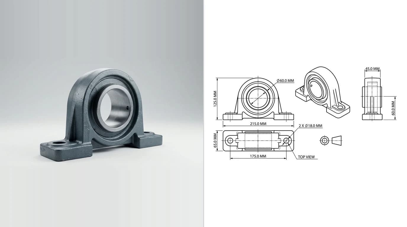
Ø precedes every diameter. Ø12 is a 12 mm hole or shaft. The habit that trips beginners is that Ø turns up where no circle is drawn: a turned shaft shown side-on is dimensioned Ø20, Ø16, Ø12 along its steps, because each step is round even though you are looking at rectangles. That is also the clue for reading the part. See Ø on a side view, think lathe.
R precedes every radius. R5 on a corner means the edge is rounded by an arc of 5 mm radius. Fillets (inside corners) and rounds (outside corners) are both dimensioned with R, and a leader arrow points at the arc rather than boxing it with extension lines. Where the radius must be genuinely smooth for stress or sealing reasons, CR, controlled radius, tightens the rule: the arc must be a fair curve with no flats.
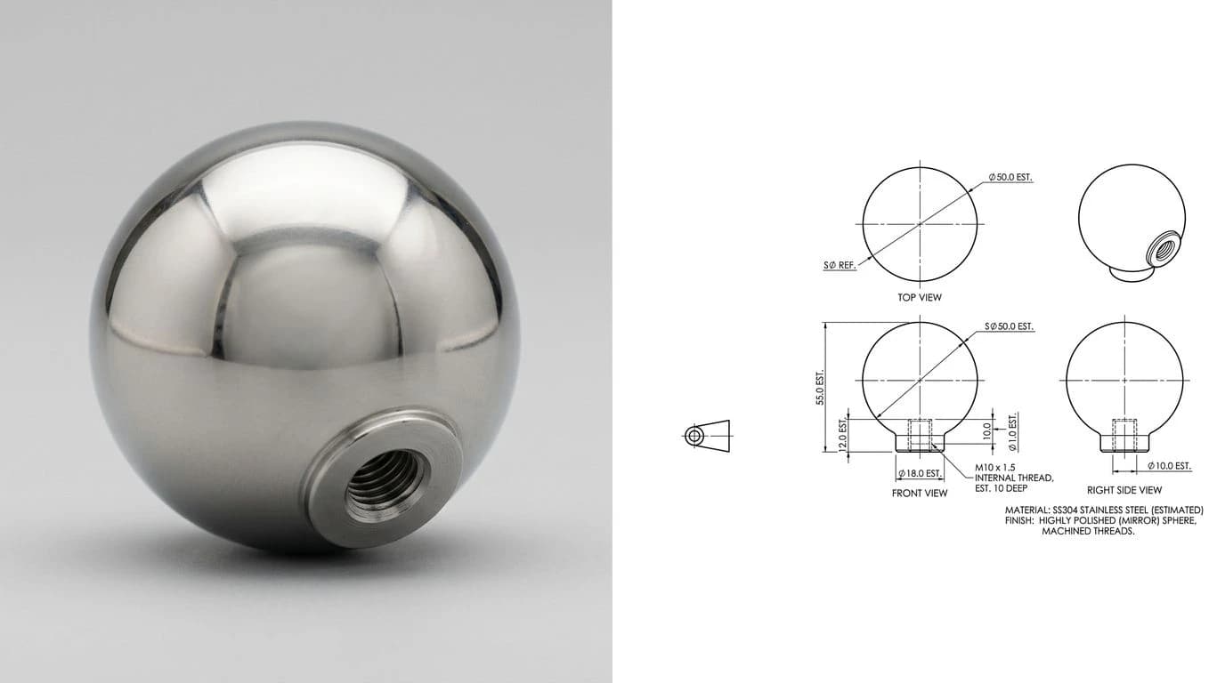
Add an S and the feature leaves the flat page: SR25 is a ball end of 25 mm radius, and SØ50 a full 50 mm sphere. One letter is the whole difference between milling a round slot and turning a ball, so it is worth the double take.
Hole callouts: ⌴, ⌵ and depth
Holes carry the densest shorthand on the drawing, and the trick that unlocks all of it is that a hole note reads in the order the machinist works. First the drill, then whatever enlarges the top of the hole, then how deep each step goes:
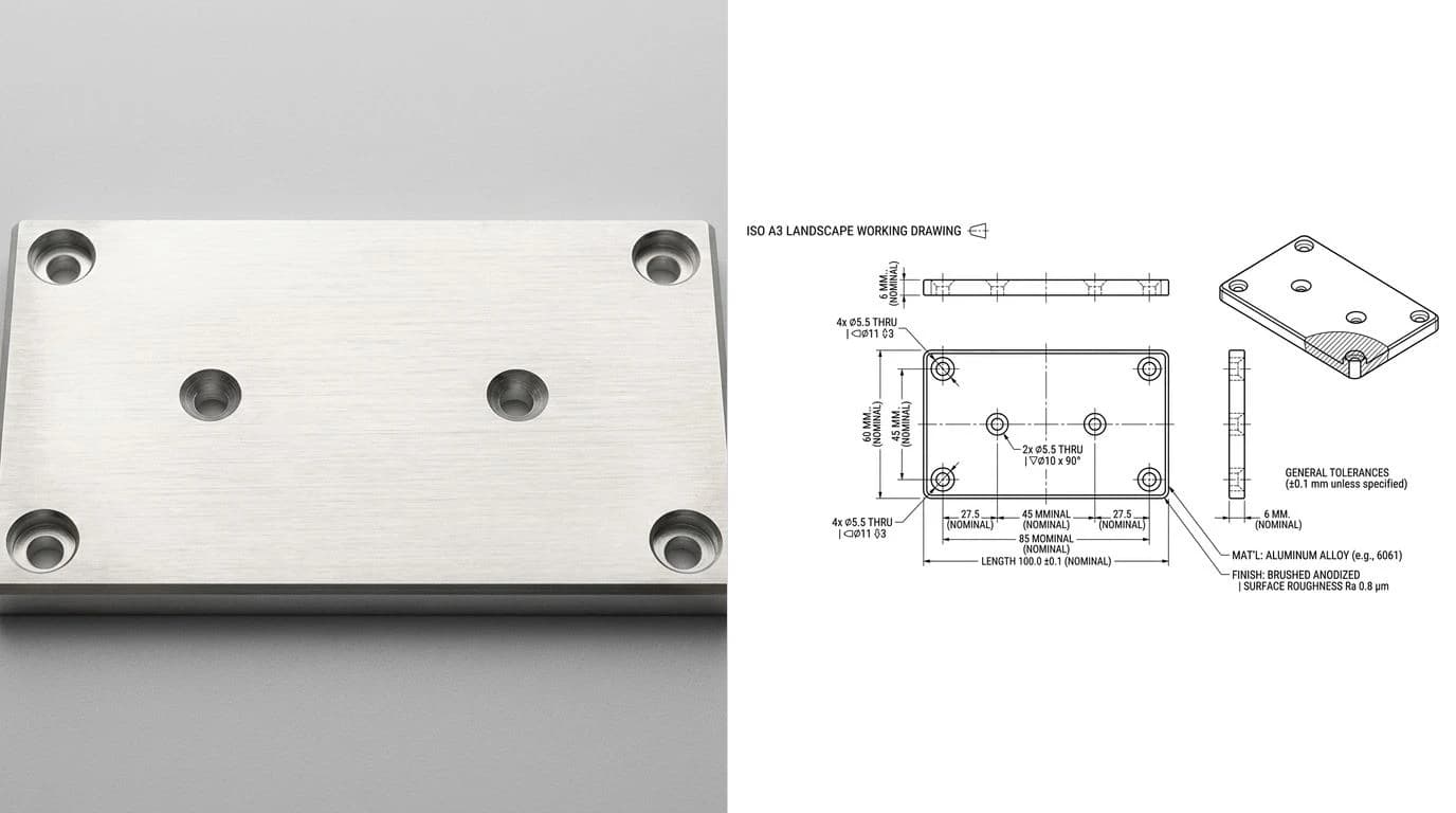
Ø6.6 ↧ 20means drill 6.6 mm, 20 mm deep. No depth symbol and no note means the hole goes through; many drawings sayTHRUanyway to remove doubt.Ø6.6 THRU, ⌴ Ø11 ↧ 6.5is a through hole with a counterbore: an 11 mm flat-bottomed recess, 6.5 mm deep, that lets a socket head cap screw sit below the surface.Ø5.5 THRU, ⌵ Ø10.4 x 90°is a countersink: a 90 degree cone opening to 10.4 mm, matching the underside of a flat head screw.- A spotface uses the counterbore symbol, often with SF added. It is a shallow cleanup cut that gives a bolt head a flat seat on a rough or cast surface.
Chamfer callouts
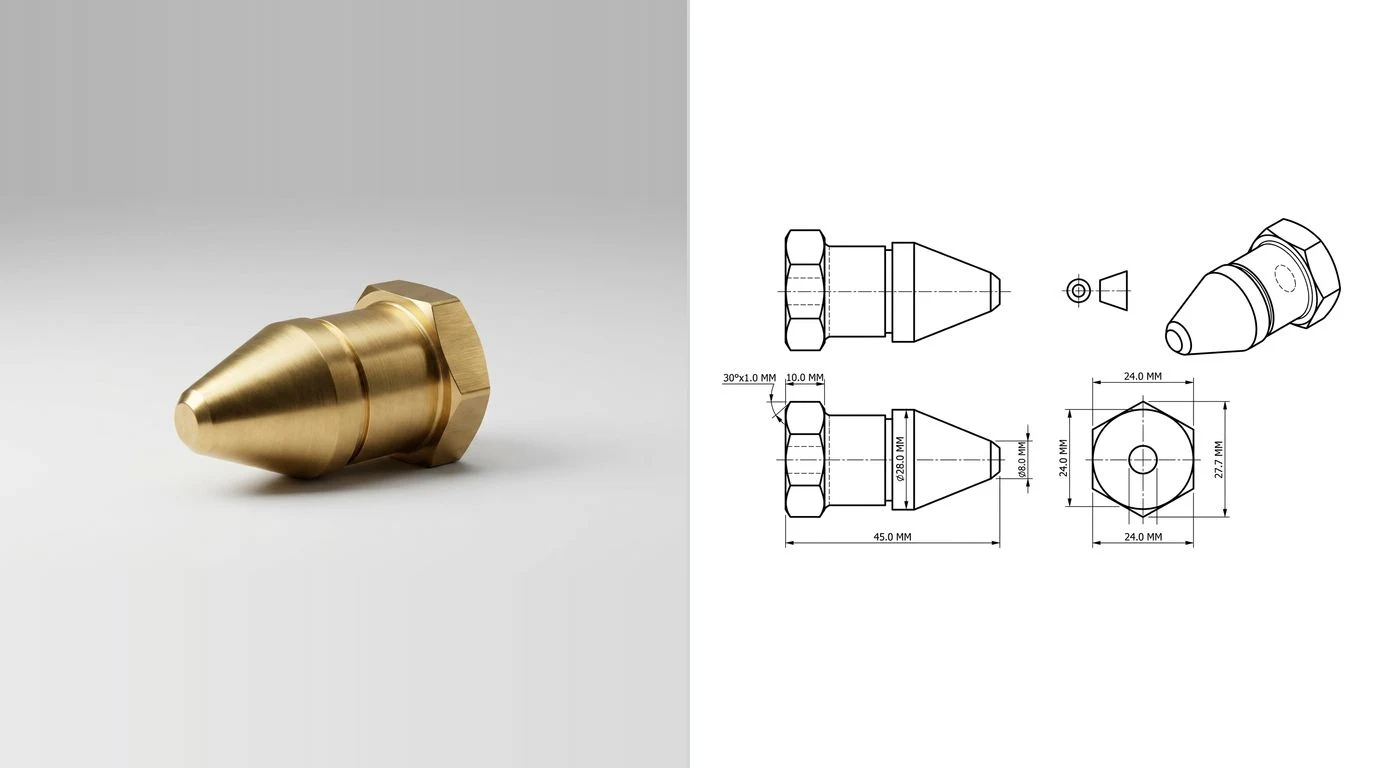
A chamfer is a small bevel that kills a sharp edge, eases assembly or leads a thread. At 45 degrees it gets the compact form: 2 x 45°, leg length then angle, or the even shorter C2. Both mean the same cut. At any other angle the drawing dimensions the chamfer with two values instead, either two leg lengths or one leg and the angle, because “C” shorthand is reserved for 45 degrees where the legs are equal by definition.
Taper and slope
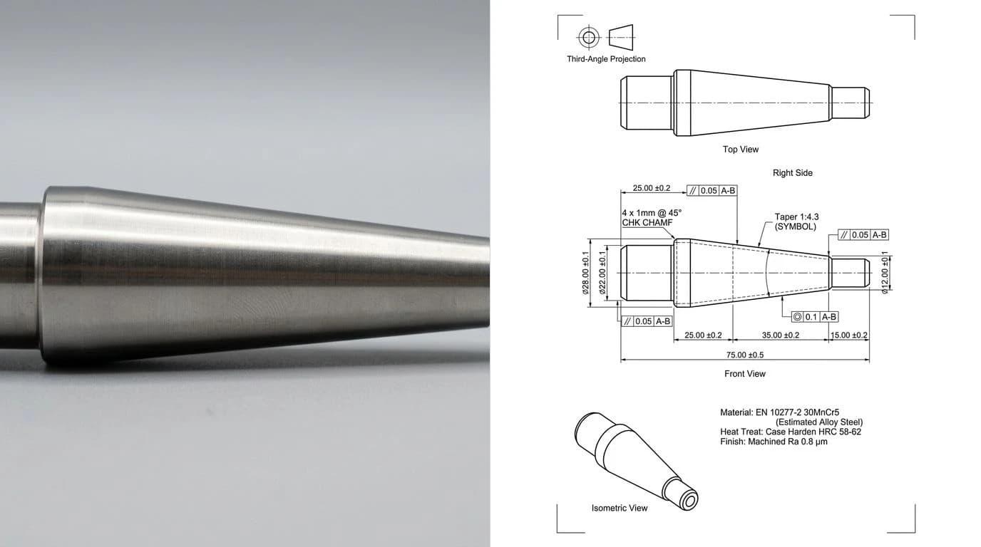
Both symbols describe a controlled incline as a ratio. Conical taper ⌲ applies to round features: a callout like ⌲ 1:5 says the diameter shrinks 1 mm for every 5 mm of length. Machine tapers, Morse sockets and self-holding tool shanks live on this symbol. Slope ⌳ is the flat-surface version, height change over length, common on wedges, gibs and draft surfaces. The symbol sits on a leader pointing at the inclined surface, with the ratio alongside.
Thread callouts
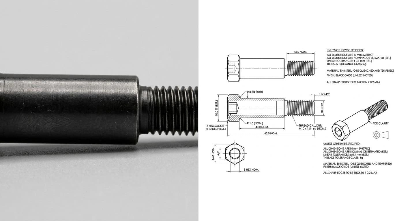
Threads are never drawn tooth by tooth; a simplified symbol stands in and the callout does the talking. Metric reads M10 x 1.5 - 6g: 10 mm nominal diameter, 1.5 mm pitch, and a tolerance class. Coarse pitch may be omitted, so plain M10 implies 1.5. Unified inch threads read 3/8-16 UNC-2B: diameter, threads per inch, series and class, where B is internal and A external. Pipe threads add their own families, NPT tapered ones among them, which is why a thread callout should never be guessed from the drawing scale.
The small print: 4x, ( ), NTS and friends
- 4x, 6x, 8x. Repetition counts. One callout, many identical features, usually holes in a pattern.
- (50). Reference dimension. Information only, controlled elsewhere, no tolerance, nobody inspects it.
- A dimension underlined straight (or marked NTS) is not to scale: the number is right, the picture is not. Trust the number.
- □10. Square cross-section, 10 mm across flats, dimensioned once instead of twice.
- TYP. Typical: the dimension applies to every feature that looks the same. Modern standards prefer explicit counts, but you will meet TYP on older drawings for decades yet.
These modifiers interact with tolerances more than people expect. A reference dimension carries none, a repeated dimension carries its tolerance at every instance. How those tolerances are read and stacked is its own guide, how to read tolerances on a drawing.
Reading a callout end to end
Put it together on one realistic hole note: 4x Ø6.6 THRU ⌴ Ø11 ↧ 6.5. Four identical holes. Each drilled 6.6 mm straight through. Each counterbored 11 mm across, 6.5 mm deep. Nothing in the note is decoration, and the machinist can set up the job from that one line without measuring the picture. That is the entire philosophy of dimension symbols: the drawing shows shape, the callouts carry truth. Reading whole drawings this way, views, section cuts and all, is covered in how to read a technical drawing, and writing them well in how to dimension a technical drawing.
One honest note from our side. When TechDraw AI rebuilds a drawing from a photo, these are exactly the symbols it places, Ø and R callouts, chamfers, hole notes, thread designations, because a drawing without them is just a picture with numbers nearby. The examples on this page are real outputs of that pipeline, imperfections included, not illustrations drawn for the article.
Where GD&T takes over
Dimension symbols answer “what size is it?”. They say nothing about how far a real, imperfect part may drift from the ideal before it stops working. That second question belongs to GD&T, feature control frames, datums, position and flatness, and it has its own vocabulary sitting on top of everything here. When you are comfortable with this page, the engineering drawing symbols and GD&T guide is the next step, and what makes a drawing manufacturing ready shows how both layers come together on a drawing a shop will actually quote.
Frequently asked questions
What does the Ø symbol mean on a drawing?
Ø means diameter. A callout like Ø12 tells you the feature, usually a hole or a shaft, measures 12 mm across its full width through the centre. It applies to the diameter even when the leader points at the edge of the circle, and on turned parts it is often used on the side view where no circle is visible at all. Watch the character itself: the drafting symbol is a circle crossed by a shallow diagonal, not the Scandinavian letter Ø and not a zero with a slash, and files that substitute one of those often lose the glyph entirely when the drawing is opened on another machine. If you have a symbol in front of you and no name for it, our drawing symbol finder looks them up by shape rather than by name.
What is the difference between R and SR on a drawing?
R is a plain radius, the distance from a centre to an arc drawn on a flat plane, like a rounded corner. SR is a spherical radius, meaning the surface curves in three dimensions like a ball end. The same pairing exists for diameters: Ø for a circle, SØ for a full sphere.
What do the counterbore and countersink symbols look like?
A counterbore is a flat-bottomed enlargement for a socket head cap screw and its symbol is an open-topped square bracket shape, ⌴. A countersink is a cone-shaped enlargement for a flat head screw and its symbol is a wide V shape, ⌵. Both appear in a hole note after the drill diameter, each followed by its own diameter, and the counterbore also gets a depth.
What does 2 x 45° mean on a drawing?
It is a chamfer callout: a bevelled edge cut 2 mm deep at a 45 degree angle. The first number is the leg length, the second the angle. You may also see it written as C2, which is shorthand for the same 45 degree chamfer, or as two separate leg dimensions when the angle is not 45 degrees.
What does 4x mean in front of a dimension?
It is a repetition count. 4x Ø6.5 means there are four identical holes of 6.5 mm diameter, dimensioned once instead of four times. The count covers every feature the callout pattern applies to, so you drill four holes even though only one carries the note.
What does a dimension in parentheses mean?
It is a reference dimension, given for convenience only. It repeats information already controlled elsewhere on the drawing, so it carries no tolerance and no inspector measures against it. If a parenthesised number disagrees with the controlling dimensions, the controlling dimensions win.