A dimension tells a shop how big to make a feature. A surface finish symbol tells it how smooth to leave the face — and getting that one small tick wrong is how a sealing surface leaks, a bearing seat seizes, or a part that measures perfectly still fails on the bench. This guide decodes the surface roughness symbols on a drawing: what the tick means, what Ra 3.2 is telling you, how Ra differs from Rz, and the chart that ties roughness to the machining process that produces it.
The short answer
On a drawing, a surface finish requirement is a small tick symbol placed on a face, its extension line, or in a note, with a roughness value written next to it. The value is almost always Ra in micrometres, and it is a maximum: Ra 3.2 means “no rougher than 3.2 µm average, smoother is fine.” A bar added to the tick forces the surface to be machined; a circle forbids machining. Everything below is the detail behind that one rule — and why the number you choose quietly sets the price of the part.
Why surface finish exists at all
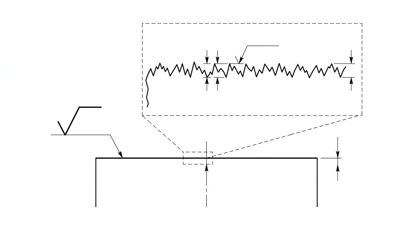
No machined surface is truly flat. Zoom in far enough and every face is a landscape of microscopic peaks and valleys left by the cutting tool, the grinding wheel or the casting mould. Surface finish — also called surface roughness or surface texture — is the way a drawing puts a number on how tall those peaks and valleys are allowed to be.
It exists for the same reason tolerances do: function versus cost. A hydraulic bore that has to hold an O-ring seal needs a controlled, fairly smooth wall or it will weep. A shaft running in a plain bearing needs a fine finish or it will wear and gall. But the bracket that just bolts to a wall does not care in the slightest, and demanding a mirror finish on it only burns money. Surface finish is how you say “this face is doing a real job” to the person quoting and cutting the part. It is a cousin of dimensional tolerance — different thing, same spirit — and if you have not read our guide to reading tolerances on a drawing, that is the natural companion to this one.
Anatomy of a surface finish symbol
The base symbol is deceptively simple: a short stroke rising into a longer one, so the whole thing looks like a check mark or an elongated square-root radical sign. That basic tick sits on the surface it controls. What you add to it changes its meaning entirely, and there are three variants you must be able to tell apart at a glance.
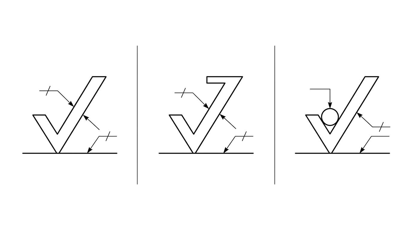
- Basic symbol (plain tick). Says a surface finish applies but does not, on its own, insist on how the surface is made. In practice it rarely appears alone.
- Machining required (tick with a bar). A short horizontal bar closes the top of the longer leg. Material must be removed — turned, milled, ground and so on — to reach the stated roughness.
- Machining prohibited (tick with a circle). A small circle sits in the vee of the tick. The surface must be left in its as-produced state — as cast, forged, moulded or extruded — and not machined.
Around that tick, several pieces of information can be hung, each in a fixed position:
- The roughness value (for example
Ra 3.2) goes above or to the left of the tick. This is the number you read first. - The production method(such as “ground” or “milled”) can be written along the horizontal bar when a specific process is mandated.
- Waviness — the longer-wavelength undulation underneath the fine roughness — can be called out separately when it matters for sealing or contact.
- The lay symbol sits at the lower right and fixes the direction of the tool marks:
=parallel, a perpendicular sign for at right angles,Xcrossed,Mmultidirectional,Ccircular,Rradial. Lay matters wherever a seal drags across a surface or two faces slide.
What does Ra 3.2 mean on a drawing?
Ra 3.2 is the single most common surface finish callout you will see, so it is worth pinning down exactly. Ra stands for roughness average: take the measured profile of the surface, draw a mean line through it, and average the absolute height of every peak and valley away from that line. The result — here 3.2 micrometres — is Ra. A smaller Ra is a smoother surface.
3.2 µm is the finish a sharp milling cutter or a lathe leaves on a normal pass without any special effort: smooth to the touch, with a faint, even sheen and visible fine tool marks under a raking light. It is the default for the majority of machined features that mate or are handled but do not seal or slide. Because the value is a ceiling, a part that comes off the machine at Ra 1.6 still passes an Ra 3.2 callout — smoother is always acceptable unless a minimum is also stated.
Ra vs Rz vs Rmax: what they measure
Ra is the most quoted parameter, but it is not the only one, and the differences bite. All of them describe the same rough profile; they just reduce it to a number in different ways.
- Ra — the arithmetic average roughness. It averages the whole profile, so a single freak spike barely moves it. Great for a general sense of texture; poor at catching one bad scratch.
- Rz — the average peak-to-valley height, taken over several sample lengths. Because it looks at the extremes rather than the average, it is far more sensitive to isolated peaks and deep valleys.
- Rmax (or Rt) — the single largest peak-to-valley height anywhere in the assessment length. The strictest of the three; used where one flaw is one too many, such as sealing and fatigue-critical surfaces.
The trap: on the same surface these give very different numbers. Rz is always larger than Ra, typically by a factor of four to seven depending on the process, and Rmax larger still. So you can never treat “Rz 10” and “Ra 10” as the same requirement — one is roughly a mid-range machined finish and the other is far finer. Read the two-letter prefix before you read the number.
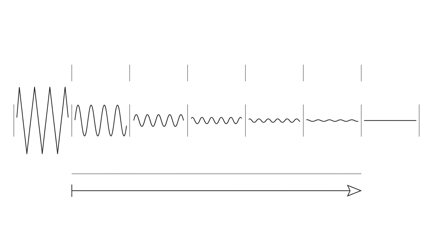
Visually, moving from a coarse to a fine surface looks like this: the deep, tall peaks and valleys on the left flatten into a nearly mirror profile on the right, and every roughness parameter shrinks together.
Surface finish N grades and the roughness chart
Older drawings, and plenty of current ones, use N grades instead of a raw Ra value. They come from ISO 1302 and run from N1 (smoothest) to N12 (roughest). Each grade is just a label for a fixed Ra value, and each step up the number doubles the roughness. If you see an N grade, this is the conversion you need.
Surface finish N grades to Ra (µm and µin)
| N grade | Ra (µm) | Ra (µin) | Typical feel |
|---|---|---|---|
| N1 | 0.025 | 1 | Mirror / lapped |
| N2 | 0.05 | 2 | Lapped, polished |
| N3 | 0.1 | 4 | Fine ground |
| N4 | 0.2 | 8 | Ground |
| N5 | 0.4 | 16 | Fine ground / honed |
| N6 | 0.8 | 32 | Fine turning / grinding |
| N7 | 1.6 | 63 | Good machining |
| N8 | 3.2 | 125 | Typical machining |
| N9 | 6.3 | 250 | Rough machining |
| N10 | 12.5 | 500 | Coarse, ridged |
| N11 | 25 | 1000 | Very rough |
| N12 | 50 | 2000 | Flame / saw cut |
Two anchors worth memorising: N8 is Ra 3.2 (the default machined finish) and N6 is Ra 0.8 (a fine, sealing-grade finish). The µin column matters if you work to drawings from the US, where microinches are still common — Ra 3.2 µm is 125 µin.
Surface finish by machining process
Roughness is not free-floating — it is a direct consequence of how the surface is made. Each process has a band of Ra it naturally produces; pushing below that band means adding a finer, slower, pricier operation. This is the table that turns a finish callout into a cost and a plan.
Typical achievable Ra by process (µm)
| Process | Typical Ra (µm) | Notes |
|---|---|---|
| Flame / plasma cut | 12.5 – 25 | Coarse edge, usually cleaned up later |
| Sawing | 6.3 – 25 | Stock cut-off, not a finish surface |
| Drilling | 1.6 – 6.3 | Bore wall from a twist drill |
| Milling | 0.8 – 6.3 | Depends on tool, feed and pass |
| Turning | 0.4 – 6.3 | Finer with a sharp tool and light finishing cut |
| Reaming | 0.8 – 3.2 | Cleans and sizes a drilled hole |
| Grinding | 0.1 – 1.6 | The usual route to a fine finish |
| Honing | 0.05 – 0.4 | Bores and cylinder walls |
| Lapping / polishing | 0.012 – 0.2 | Mirror finishes, sealing and optical faces |
Read this table alongside the finish callout. If a drawing asks for Ra 0.4 on a face, you are implicitly asking for grinding or better — turning alone will not reliably get there. Ask for Ra 0.05 and you have committed the part to honing or lapping, with the time and cost that implies.
How smooth is smooth enough?
The instinct to spec a fine finish “to be safe” is exactly the instinct that blows up a quote. Every step smoother demands a finer process, a slower cut, more setups and more inspection. As with tolerances, the discipline is to ask for the loosest finish the feature can still do its job with. A few working rules:
- Only finish what functions. Sealing faces, bearing seats, sliding surfaces and mating datums earn a fine finish. Free surfaces that are never touched can stay at the default machined roughness or better.
- Match the finish to the process you are already using. If the part is turned,
Ra 1.6–3.2comes almost for free; demandingRa 0.2bolts a whole grinding operation onto the job. - Let function set the number. O-ring dynamic seals often want around
Ra 0.4–0.8; general machined mating facesRa 1.6–3.2; cosmetic-only or non-contact facesRa 6.3or looser.
This is the same trade-off — tighter equals costlier — that governs dimensional tolerance, and the two decisions are usually made together on the same feature. The tolerances guide covers the dimensional half; this one covers the texture.
Reading a surface finish callout on a real drawing
Put it together with a worked example. Suppose a shaft feature carries a tick with a bar, Ra 0.8 above it, the word “ground” on the bar, and an = lay symbol at the lower right. Read left to right and top to bottom:
- Tick with a bar → the surface must be machined (material removed).
- Ra 0.8 → the average roughness may not exceed 0.8 µm — a fine, sealing-grade finish (grade N6).
- “ground” → the shop is told to reach it by grinding, not just a fine turning pass.
- = lay → the tool marks must run parallel to the indicated edge, which matters for how a seal rides on the shaft.
One callout, four separate instructions. Miss the lay symbol and you can machine a shaft that measures perfectly, hits its Ra, and still leaks because the scratch pattern runs the wrong way. Surface finish is one of the notations that separates a drawing that looks complete from one that is genuinely manufacturing-ready. For the broader family of drafting and geometric symbols that live alongside it, see our engineering drawing symbols and GD&T guide.
Surface finish on a photo-based drawing
A quick honest note on where automation stops. If you are generating a drawing from a photo of a part — which is exactly what TechDraw AI does — the tool can capture the shape, the proportions and a clean set of views. What it cannot read from a photo is surface finish: a picture cannot tell whether a bore was honed for a seal or left as a rough drilled hole. Roughness is a functional requirement, not a visible feature.
So the workflow is a hand-off. Let the AI do the geometry: turn your photo into a dimensioned, editable drawing in seconds. Then you, the engineer who knows what the part has to do, add the surface finish ticks and Ra values to the faces that seal, bear or slide — using exactly the chart above to pick sane numbers. That division of labour — machine does the drafting, human owns the function — is the whole idea. Try it with a photo of your part and add the finish callouts yourself.
Frequently asked questions
What does Ra 3.2 mean on a drawing?
Ra 3.2 means the surface is allowed an average roughness (Ra) of 3.2 micrometres. Ra is the arithmetic average of the height of the tiny peaks and valleys along the measured profile, so a smaller number is a smoother surface. 3.2 µm is a normal, general-machining finish — the kind a milling cutter or a lathe leaves on a typical part without any extra finishing. Unless a note says otherwise, the value is the maximum permitted, so anything smoother than Ra 3.2 also passes.
What is the difference between Ra and Rz?
Ra and Rz measure the same rough profile in two different ways. Ra is the arithmetic average roughness over the whole sampling length, so it smooths out one-off spikes. Rz is the average distance between the highest peaks and the lowest valleys, so it is far more sensitive to isolated defects like a single deep scratch. On the same surface Rz is always numerically larger than Ra — roughly four to seven times, depending on the machining process — which is why you can never simply swap one value for the other.
What is the machining surface finish symbol?
It is a small tick that looks like an elongated check mark or a square-root radical sign, sitting on the surface or its extension line. The plain tick is the basic symbol. Add a short horizontal bar across its open leg and it means material removal by machining is required. Draw a small circle in the vee of the tick and it means material removal is prohibited — the surface must be left as cast, forged or moulded. The roughness value, such as Ra 3.2, is written next to the tick.
How do surface finish N grades convert to Ra?
The N grades are a shorthand scale from N1 (smoothest) to N12 (roughest), each mapping to a fixed Ra value in micrometres. The common ones: N6 = Ra 0.8, N7 = Ra 1.6, N8 = Ra 3.2, N9 = Ra 6.3 and N10 = Ra 12.5. Each step up the N number doubles the Ra value. The grades come from the older ISO 1302 system and still appear on many drawings, though modern practice is to state the Ra value directly.
What is the lay direction symbol in surface finish?
Lay is the direction of the dominant surface pattern left by machining — the visible tool marks. A lay symbol is added at the lower right of the surface finish tick to require a particular direction: an equals sign means lay parallel to the edge the symbol points to, a perpendicular sign means at right angles to it, an X means crossed, an M means multidirectional, a C means circular and an R means radial. Lay matters for seals, sliding surfaces and anything where the scratch pattern affects friction or leakage.
Is a lower Ra number smoother or rougher?
Lower is smoother. Ra is a measure of how tall the surface's peaks and valleys are, so the smaller the number, the flatter and more polished the surface. Ra 0.4 is a fine ground finish, Ra 3.2 is typical machining, and Ra 12.5 is a coarse, clearly ridged surface. Because smoother surfaces cost more to produce, the goal on a drawing is the largest Ra value the part can still function with.
Sources
- ISO 21920-1:2021: Geometrical product specifications (GPS) — Surface texture: Profile — Indication of surface texture
- ISO 1302:2002: Indication of surface texture in technical product documentation (the earlier symbol standard)
- ASME B46.1: Surface Texture (Surface Roughness, Waviness, and Lay) — the US standard
- Engineering ToolBox: surface roughness Ra values by machining process