
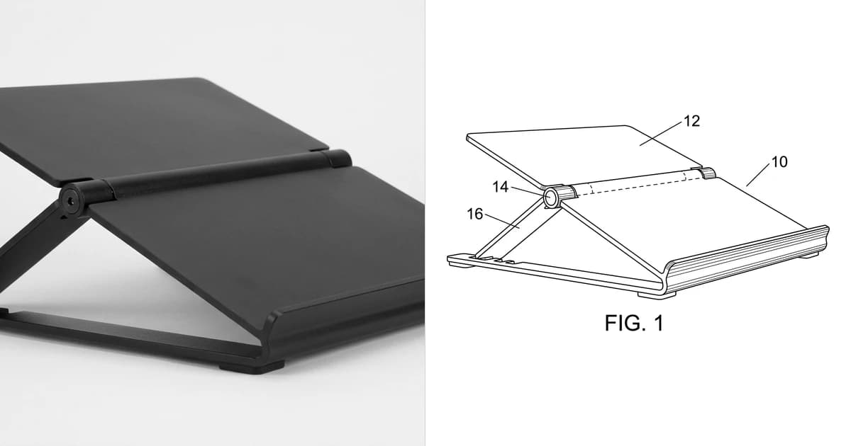
You have a working prototype on the bench and a filing date you would like to stop postponing. The drawings are the part everyone underestimates, partly because they look like the easy bit and partly because engineers assume the CAD drawing they already have will do. It will not, and the reasons are specific enough to be worth an afternoon. Here is what the rule actually says, checked against the regulation rather than repeated from other people's blog posts.
Our articles are still written by humans!
Get human written articles in your Google feed.
The short answer
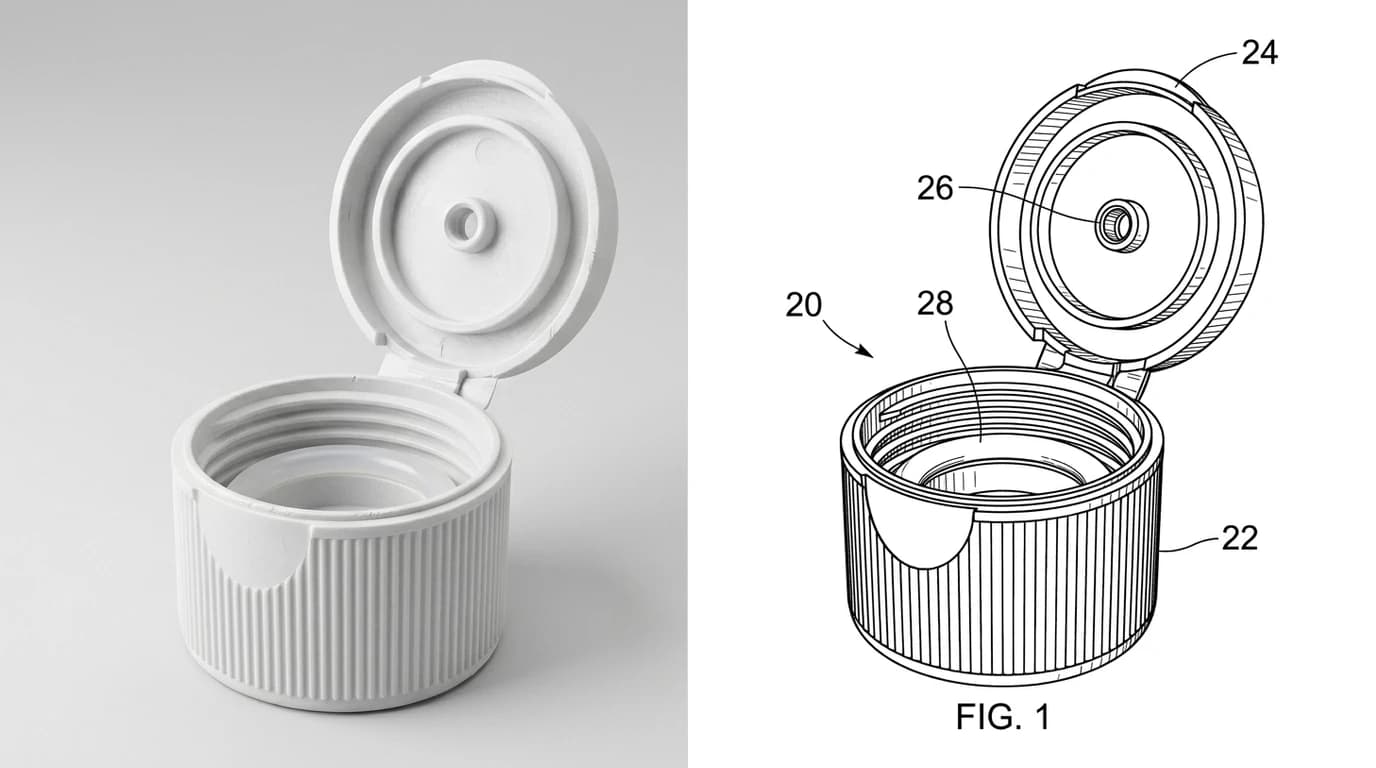
A United States patent drawing is a black line drawing on a white sheet, with no colour, no greyscale, no dimensions and no measurements. Parts are identified by bare numerals sitting in white space, each joined to its feature by a short lead line. Views are captioned FIG. 1, FIG. 2 and so on in consecutive Arabic numerals. Shading, where it is used at all, is done with spaced parallel lines and not with tone.
Every one of those choices is the opposite of what you would do on a manufacturing drawing, which is why exporting your CAD sheet and filing it is such a reliable way to attract an objection.
This page is about the figures themselves. If you are earlier than that and still working out the filing, the fees and the deadlines, start with how to patent an idea, which covers the sequence, the current USPTO fee schedule and the one year clock your own public disclosure starts.
A patent drawing is not a CAD drawing
The two documents answer different questions. A manufacturing drawing answers “how do I make exactly this?” A patent figure answers “what is the thing I am claiming?” Once you hold those two questions side by side, the formatting rules stop looking arbitrary.
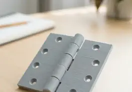
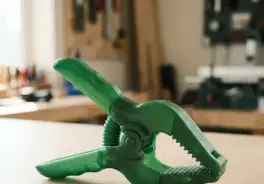
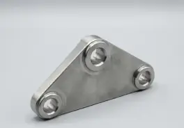
The same object, two documents, almost no overlap in convention
The dimensions row is the one that generates arguments, so let us be precise about it. 37 CFR 1.84 does notcontain a sentence saying “do not put dimensions on the drawing”. Anyone who tells you it is expressly forbidden has not read the rule. What the rule forbids, in paragraph (k), is a scale indication: it says indications such as “actual size” or “scale 1/2” are not permitted, on the grounds that they lose their meaning when the drawing is reproduced in a different format.
The reason dimensions stay off is separate and more important. A patent figure is read alongside the claims, and anything visible in the figure can be argued about later. Printing “42.0 mm” on a part invites the argument that you claimed a 42 mm part. Leaving it off costs you nothing, because the figure was never going to be used to manufacture anything. If you need both documents, and most hardware inventors eventually do, make them separately.
What 37 CFR 1.84 actually requires
The rule runs from paragraph (a) to paragraph (y). Most of it is uncontroversial once you read it. These are the paragraphs that decide whether a set gets through.
The paragraphs of 37 CFR 1.84 that most often decide whether a drawing set is accepted
Two of these are worth expanding. The margin rule is asymmetric, and people who centre their drawing on the page get caught by it: the top and left need a full inch, the right needs 5/8 inch and the bottom 3/8 inch. That asymmetry exists because of how the sheets were historically bound and reproduced.
The scale rule in paragraph (k) is really an instruction about legibility. It says the drawing must be large enough to show the mechanism without crowding when reduced in size to two-thirds in reproduction. That is a test you can actually run: print the sheet at 67 percent and see whether the numerals and the fine detail survive. A surprising number of computer-generated figures do not.
Can you just file the photograph?
You have a good photo. The temptation is obvious, and the answer is almost always no. 1.84(b) says photographs, including photocopies of photographs, are not ordinarily permitted in utility and design applications. They are accepted when photographs are the only practicable medium for illustrating the claimed invention.
“Only practicable medium” is a genuinely high bar. It covers things a line drawing cannot represent at all: crystalline structures, certain histological specimens, some metallurgical microstructures. It does not cover a housing, a linkage, a bracket or a moulding, because a line drawing represents all of those perfectly well and, from the examiner's point of view, more clearly.
Design applications add a further restriction under 1.152: photographs and ink drawings may not be combined as formal drawings in one application, and a photograph filed in place of ink drawings must not disclose environmental structure. In other words a photograph of your product sitting on a desk, with the desk visible, is disclosing things you did not claim.
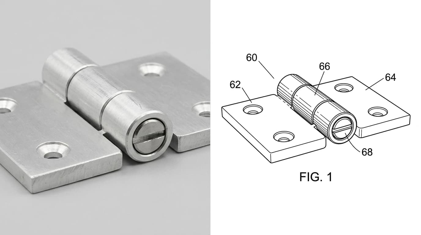
So the photograph is not the filing. It is the input, and that is a different and much better role for it.
Reference numerals, where most sets fail
This is where engineers reliably import a habit from the wrong document. On a manufacturing or inspection drawing, a part or a characteristic gets a balloon: a number inside a circle. It is standard, it is correct, and on a patent figure it is a defect.
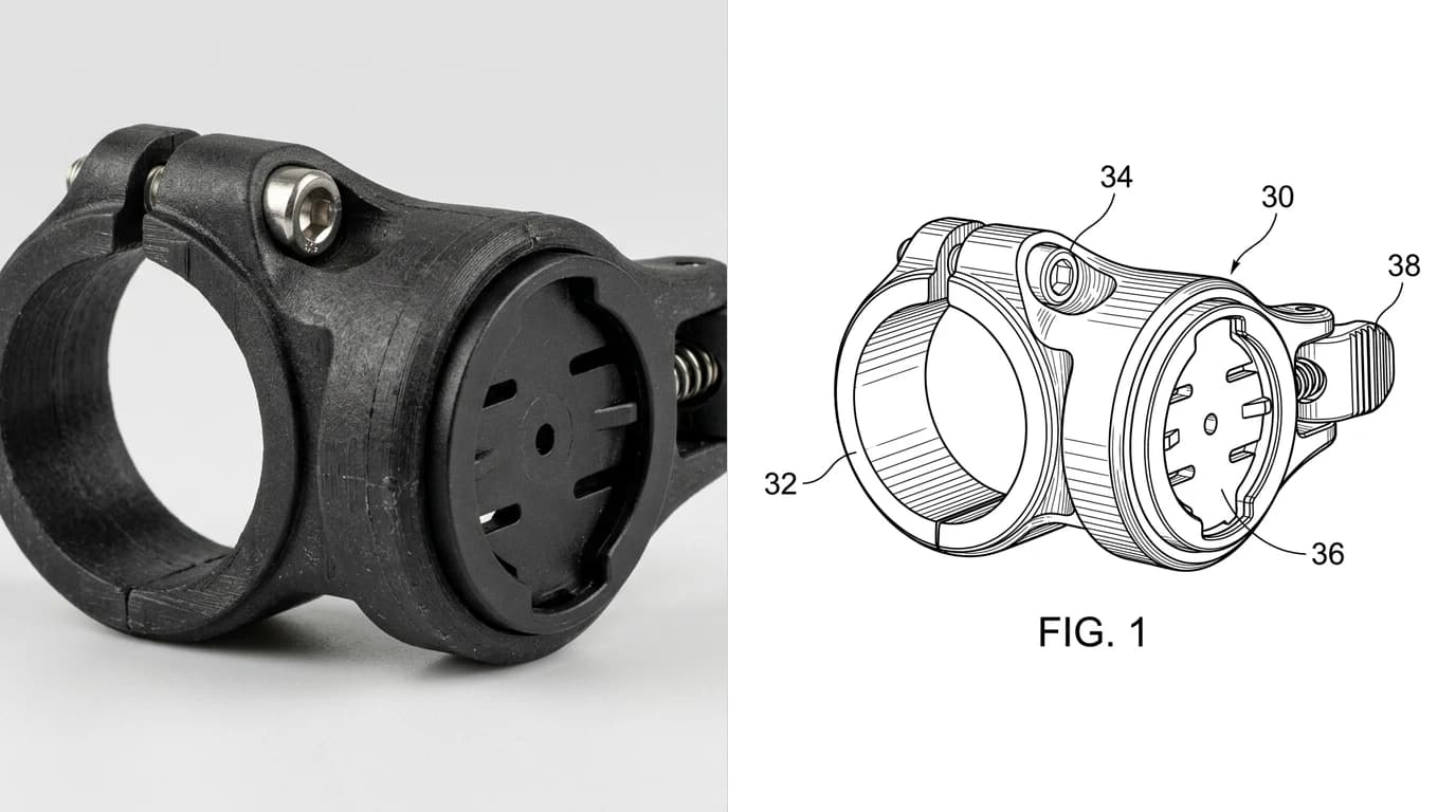
1.84(p)(1) is explicit. Reference characters, sheet numbers and view numbers must be plain and legible, and must not be used in association with brackets or inverted commas, or enclosed within outlines, e.g., encircled. No circle, no box, no brackets, no quotation marks. The numeral sits bare in white space.
The companion rule is 1.84(q) on lead lines. A lead line must originate in the immediate proximity of the reference character and extend to the feature indicated, and should be as short as possible. It may be straight or curved. What it may not be is absent: a numeral floating near a feature with no line connecting them is ambiguous, and ambiguity in a figure is exactly what an examiner is looking for.
- Numerals must be at least 0.32 cm (1/8 inch) high per
(p)(3), and must not be placed so as to interfere with comprehension of the drawing. - Use each numeral for the same feature everywhere. If 14 is the pivot in FIG. 1, it is the pivot in FIG. 4 too.
- Every numeral in the figures should appear in the specification, and every numbered element in the specification should appear in a figure. Mismatches between the two are a classic source of objections.
- Even numbers spaced 10, 12, 14 are a convention, not a rule. It leaves gaps for parts you add later, which you will.
How many views, and which ones
1.84(h)is permissive: the drawing must contain as many views as necessary to show the invention, and those views may be plan, elevation, section, partial or perspective. That freedom is real, and it is also a trap, because “necessary” is judged against your claims rather than against your sense of completeness.
The practical rule for a utility application is to work backwards from the claim language. Every element a claim recites has to be visible and numbered somewhere. If a claim says the housing defines an internal channel, and no figure shows that channel, you have a problem that adding a view later cannot fix without raising a new matter question.
- One perspective view to orient the reader. This is usually FIG. 1 and it is the figure most likely to be printed on the front page.
- Sections for anything internal. Per
1.84(h)(3), hatching indicates the sectioned portion and is made by regularly spaced oblique parallel lines, spaced far enough apart to be told apart without difficulty. - An exploded view if assembly order or part relationships are claimed.
- Detail views for small features that would otherwise be lost when the sheet is reduced to two-thirds.
Design patents play by stricter rules
If you are protecting how a product looks rather than how it works, you are in design patent territory and 37 CFR 1.152 applies on top of 1.84. The differences are sharp enough that a set drawn for a utility filing will not do.
- The drawing must contain enough views for a complete disclosure of the appearance of the design. In practice that means every surface visible in normal use.
- Surface shading is expected, not optional. The rule says appropriate and adequate surface shading should be used to show the character or contour of the surfaces represented, because in a design patent the contour is the invention.
- Solid black shading is not permitted, except to represent the colour black or colour contrast.
- Broken lines mean unclaimed. They may be used to show visible environmental structure, but may not be used to show hidden planes and surfaces that cannot be seen through opaque material. This is the single most strategically important line in the rule, because what you draw broken is what you are giving away.
- No alternate positions illustrated by full and broken lines in the same view.
From prototype photo to figure
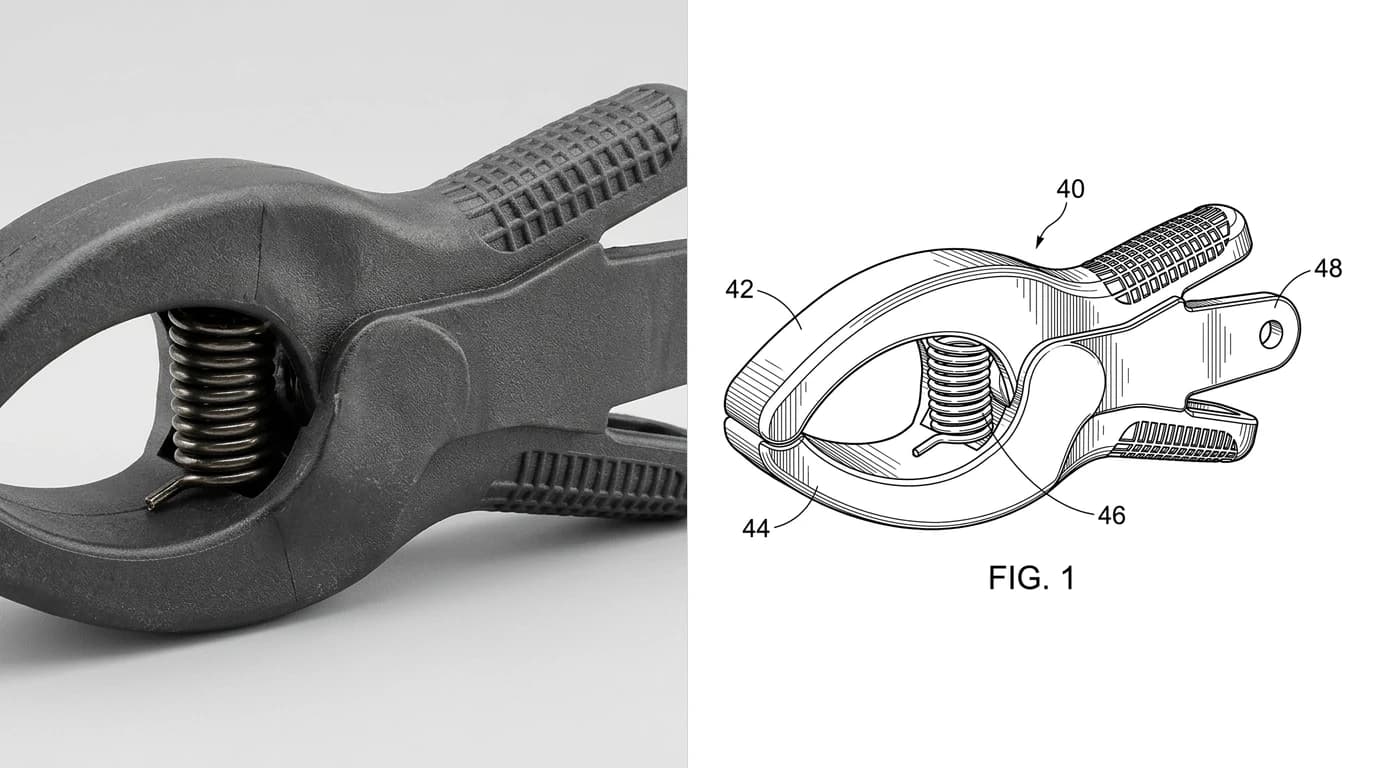
Here is where the photograph earns its place. It cannot be the filing, but it is an excellent starting point for the line work, and this is exactly the conversion our pipeline does: it reads a photograph of a real object and projects clean line geometry from it, which is the same core job described in from photo to manufacturing drawing, with the output conventions changed.
- Shoot the prototype plainly. Even light, plain background, the whole object in frame with margin around it, and no hands, packaging or branding. Our notes on shooting a part for conversion apply unchanged, and a busy background is the most common reason the line work comes back wrong.
- Shoot every face you will need to claim. For a design filing that means six orthogonal views plus a perspective, taken square on. Retaking a photo is free; redrawing a figure is not.
- Generate the line work and then strip everything a patent figure does not carry: dimensions, tolerances, centre lines, title block, scale note.
- Add reference numerals last, once you and your attorney have settled which elements the claims will recite. Numbering before the claims exist means renumbering after.
- Print at 67 percent and read it. This is the paragraph (k) test and it takes a minute.
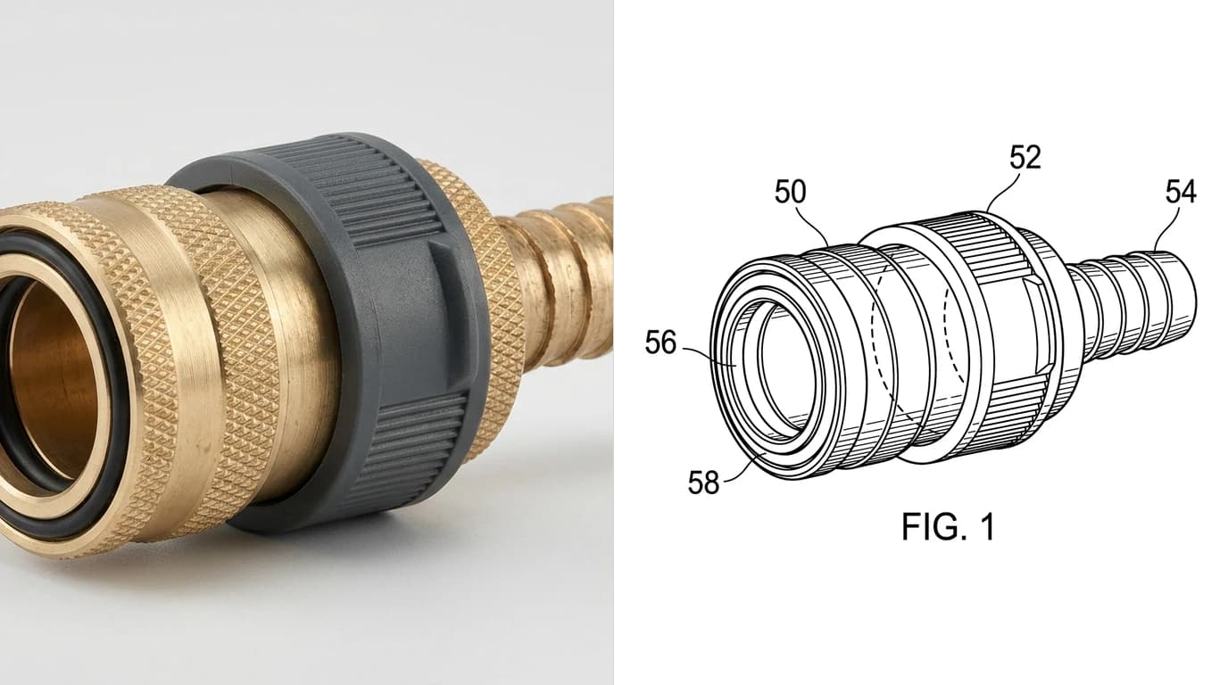
Be clear-eyed about what this gets you. It gets you figures good enough for a provisional application, good enough to put in front of an attorney so they can see what you actually built, and good enough to iterate on cheaply while the claims are still moving. For a non-provisional filing, where the figures have to line up with claim language element by element, this is a first draft that a professional should finish. We would rather say that plainly than sell you something that costs you a prosecution round.
What actually draws an objection
Almost none of the scary outcomes people describe online are real. The normal consequence of a defective drawing is a drawing objectionduring examination and an opportunity to file corrected sheets. You lose time and you pay for someone's hours. You do not lose the application.
The recurring causes, roughly in order of how often they appear:
- Grey tone or anti-aliased linesfrom a screenshot or a render, failing the “black, dense, uniformly thick” test in paragraph (l).
- Numerals in circles, straight from a CAD balloon habit, contrary to (p)(1).
- Margins too small, usually because the drawing was centred rather than set to the asymmetric minimums in (g).
- Reference numerals in the figures that never appear in the specification, or the reverse.
- Text where a numeral belongs. Legends are allowed under (o) but should contain as few words as possible, and a figure annotated like an assembly instruction is not one.
- Detail lost at two-thirds reduction, per (k).
The one that is not a formality: you cannot add new matter when correcting drawings. Fixing line weight is administrative. Adding a feature that was never shown or described is not, and that is the failure worth spending money to avoid.
What it costs and when to pay it
Advertised 2026 rates put specialist patent illustration firms at roughly 75 to 150 US dollars per sheet and general freelancers at roughly 30 to 100. A typical utility application runs four to eight sheets, which puts a full professional set somewhere around 300 to 800 dollars. Those are marketing pages rather than a survey, so treat them as an order of magnitude rather than a quote.
The useful way to think about it is not cost but sequence.
Where cheap drawings are fine and where they are a false economy
The design row has no hedge in it on purpose. Broken lines carry claim scope, so a drafting mistake there is a claiming mistake, and it is not the place to save 400 dollars.
For what the rest of the application costs, the government fees on the current schedule and how long the queue at the USPTO actually is, see how to patent an idea.
FAQ
Frequently asked questions
What are the USPTO requirements for patent drawings?
They are set out in 37 CFR 1.84. The ones that catch people are physical rather than artistic: sheets must be either 21.0 by 29.7 cm (A4) or 21.6 by 27.9 cm (8 1/2 by 11 inches); margins must be at least 2.5 cm at the top, 2.5 cm on the left, 1.5 cm on the right and 1.0 cm at the bottom; every line, number and letter must be durable, clean, black, sufficiently dense and dark and uniformly thick and well defined; reference characters must be at least 0.32 cm (1/8 inch) high; and views must be numbered in consecutive Arabic numerals starting with 1.
Can I put dimensions on a patent drawing?
Almost never, and the reason is legal rather than regulatory. 37 CFR 1.84 does not contain a sentence forbidding dimensions, so anyone telling you it is banned outright is overstating the rule. What the rule does say, in paragraph (k), is that indications such as actual size or scale 1/2 are not permitted, because they lose their meaning when the drawing is reproduced at a different size. The practical reason to leave measurements off is different: a patent figure exists to support the claims, and a number printed in a figure can later be argued to limit what you claimed. Save the dimensions for the manufacturing drawing, which is a separate document with a separate job.
Can I use a photograph instead of a drawing in a patent application?
Usually not. 37 CFR 1.84(b) states that photographs, including photocopies of photographs, are not ordinarily permitted in utility and design applications, and are accepted only when they are the only practicable medium for illustrating the claimed invention. The classic accepted cases are things a line drawing genuinely cannot show, such as crystalline structures or certain histological specimens. A photograph of a bracket, a housing or a mechanism is not one of those. In design applications there is a further restriction: photographs and ink drawings may not be combined as formal drawings in one application, and a photograph filed in place of ink drawings must not show environmental structure.
Do reference numerals go in circles on a patent drawing?
No, and this is one of the most common mistakes people bring over from engineering drawings. 37 CFR 1.84(p)(1) states that reference characters, sheet numbers and view numbers must be plain and legible and must not be used in association with brackets or inverted commas, or enclosed within outlines, for example encircled. A circled number is standard practice on an inspection drawing, where it identifies a characteristic to be measured. On a patent figure it is a formal defect. The numeral sits bare in white space with a lead line running to the feature.
How many views does a patent drawing need?
As many as necessary to show the invention, which 37 CFR 1.84(h) leaves deliberately open. For a utility patent that usually means one perspective view to orient the reader plus whatever sections, exploded views or detail views the claims require. For a design patent the bar is much more specific: 37 CFR 1.152 requires a sufficient number of views to constitute a complete disclosure of the appearance of the design, which in practice means every surface visible in normal use, typically front, rear, left, right, top, bottom and at least one perspective.
Can AI generate patent drawings?
It can generate the line work, and that is genuinely useful for a provisional filing or for showing a patent attorney what you mean. It cannot decide what to claim. The figure has to show every element the claims recite, and the reference numerals have to match the numerals used in the specification, which means the drawing and the text have to be written against each other. That coordination is legal work. Our honest position is that an AI figure is a strong first draft and a poor final filing on a non-provisional application.
What happens if my drawings do not meet the requirements?
Usually nothing dramatic, and that is worth knowing because the internet makes it sound fatal. Non-compliant drawings normally draw a drawing objection during examination, and you are given an opportunity to file corrected drawings. The real cost is time and attorney hours rather than loss of the application. The exception worth taking seriously is that new matter cannot be added when you correct a drawing, so a figure that omitted a claimed feature entirely can be a genuine problem rather than a formality.
How much do patent drawings cost?
Reported market rates in 2026 put specialist patent illustration firms at roughly 75 to 150 US dollars per sheet, and general freelancers at roughly 30 to 100 dollars per sheet. A typical utility application runs to four to eight sheets, so a full set commonly lands somewhere between 300 and 800 dollars. Those are advertised ranges rather than a survey, so treat them as an order of magnitude. The judgement is not really about the money: it is that correcting drawings later costs attorney time at a much higher hourly rate than the drawings themselves.
If what you need after the filing is the other document, the one with the numbers on it, that is a different job with different conventions: what makes a drawing manufacturing-ready covers the bar a fabrication sheet has to clear, and reverse engineering a part without the original drawing covers getting there from a physical sample. Both start from the same photograph you already took for the patent.