Drawing Scale Calculator
Type a scale any way you have it. 1:50, 1/4" = 1'-0", 1" = 20', or just 48. You get the factor, the AutoCAD settings, the converted length and the sheet it fits on.
Scale factor
50
1:50
- DIMSCALE
- 50
- LTSCALE
- 50
- Viewport zoom
- 1/50xp
- Direction
- Reduction
A measurement off the sheet into a real size, or a real size into what it will measure on the sheet. Both boxes are live, so either one drives the other.
20 mm on a 1:50 drawing is 1 m on the real thing (1000 mm).
The short answer
A scale factor is how many real units fit inside one drawn unit. 1:50 is a factor of 50. The architect's 1/4" = 1'-0" is 48, because a foot is twelve inches and 12 divided by 0.25 is 48. The engineer's 1" = 20' is 240, not 20, because twenty feet is 240 inches.
Set AutoCAD's DIMSCALE and LTSCALE to that factor, and draw model space text at your plotted height multiplied by it: 2.5 mm text on a 1:50 sheet is drawn 125 mm high. On an enlargement the factor falls below one, so a 2:1 detail is DIMSCALE 0.5.

Built and checked by Branislav Hrivnák, Co-Founder, TechDraw AI. Last checked September 2026.
What the numbers here come from
- ISO 5455:1979, Technical drawings, Scales the eighteen recommended scales in the table below, clause 5.1, and the rule that the range may be extended only by whole powers of ten.
- Autodesk, DIMSCALE (system variable) DIMSCALE is set to the inverse of the intended plot scale, and to 0 for an annotative style.
- ASME Y14.1, Drawing Sheet Size and Format the ANSI A to F inch sheet sizes in the fit panel.
The arithmetic is covered by 141 assertions that run on every change, including the cases charts get wrong: the engineer's factor of 240 rather than 20, DIMSCALE dropping below one on an enlargement, and 11 15/16 inches rounding up to 1'-0" rather than 0'-12". Every figure in the tables below is produced by the same code the calculator runs, so the two cannot drift apart.
Trusted by


What a scale factor actually is
ISO 5455 defines a scale as the ratio of a length on the drawing to the same length on the real object. That is the whole definition, and everything on this page is that one number multiplied or divided by something. The scale factor is simply that ratio turned upside down: how many real units fit inside one drawn unit.
scale factor = real length ÷ drawn length
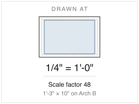
A 1:50 drawing: 10 mm on the sheet is 500 mm on the building, so the factor is 50. A quarter-inch architectural sheet: one inch on the paper is 4'-0" of building, so the factor is 48.
Where people go wrong is never that division. It is that the three systems in common use hide different things inside it, and that the factor applies to the annotation on a drawing and never to the geometry.
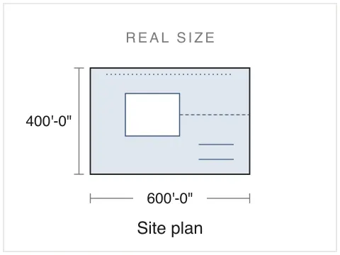
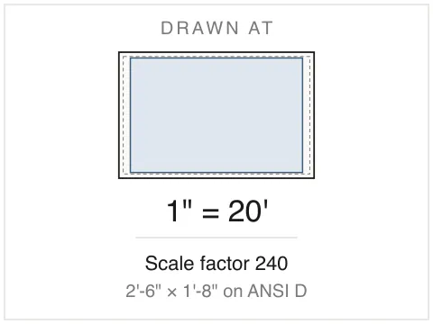
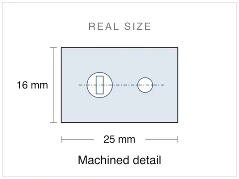
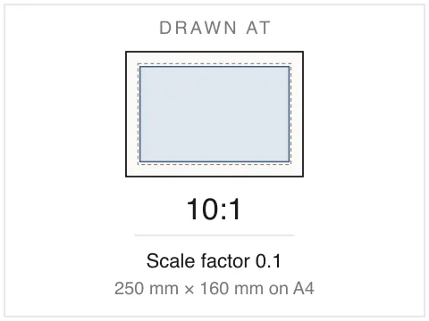
Four objects and the scale each one needs
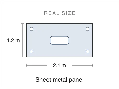
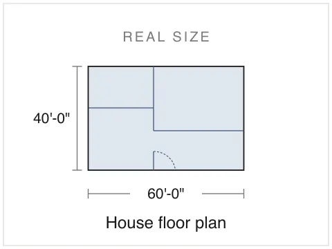
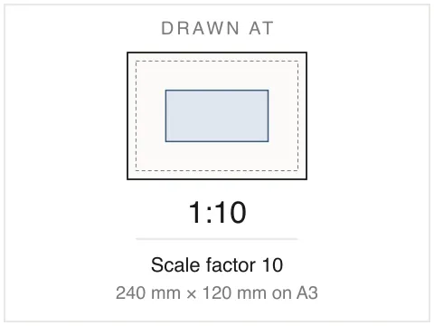
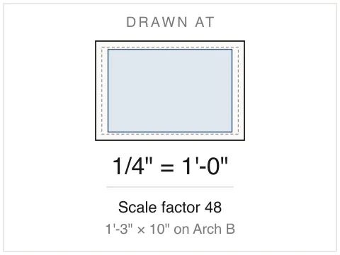
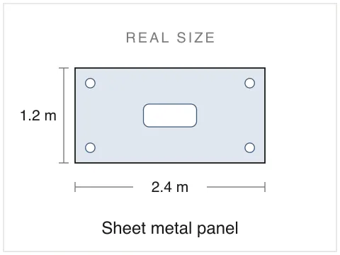
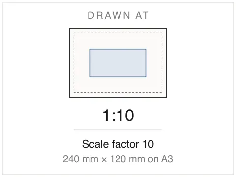
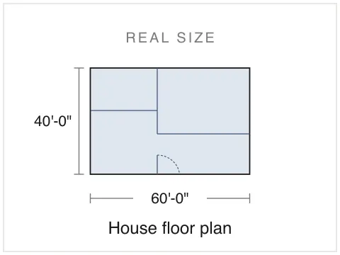
Every figure below is what the calculator above returns for that object on that sheet. The cards are drawn from the same module the tool runs, so they cannot show a scale it would not pick, and on each right hand card the sheet is at its true shape with the object placed inside at exactly the ratio named underneath.
How to work out a scale factor
Write the scale as a ratio
Every scale is one number: the length on the sheet divided by the length on the real thing. 1:50 is 0.02. A quarter-inch architectural scale is 0.25 divided by 12, which is 1/48. An engineer's 1" = 20' is 1 divided by 240. Once it is a ratio the three systems stop being different subjects.
Turn it upside down for the factor
The scale factor is the ratio inverted: 50, 48, 240. It is how many real units fit in one drawn unit, and it is the number AutoCAD wants. On an enlargement it drops below one. A 2:1 detail is a factor of 0.5, which is the case most charts leave out.
Multiply anything measured on paper by it
Text height, arrowheads, gaps, linetype pattern: everything you want a fixed size on the printed sheet gets drawn factor-times-bigger in model space. Everything that represents the real object stays at its real size. Mixing those two up is what makes a drawing plot wrong.
AutoCAD scale factor chart: architectural
The twelve scales on the faces of a triangular architect's scale. The factor is always twelve divided by the inches to the foot, because a foot is twelve inches. That is why the numbers are 4, 8, 12, 16, 24, 32, 48 and not anything rounder. The last column is what 1/8" text has to be drawn at in model space to plot that size.
| Scale | Factor / DIMSCALE | Ratio | 1" on the sheet | 1/8" text |
|---|---|---|---|---|
| 3" = 1'-0" | 4 | 1:4 | 0'-4" | 1/2" |
| 1 1/2" = 1'-0" | 8 | 1:8 | 0'-8" | 1" |
| 1" = 1'-0" | 12 | 1:12 | 1'-0" | 1 1/2" |
| 3/4" = 1'-0" | 16 | 1:16 | 1'-4" | 2" |
| 1/2" = 1'-0" | 24 | 1:24 | 2'-0" | 3" |
| 3/8" = 1'-0" | 32 | 1:32 | 2'-8" | 4" |
| 1/4" = 1'-0" | 48 | 1:48 | 4'-0" | 6" |
| 3/16" = 1'-0" | 64 | 1:64 | 5'-4" | 8" |
| 1/8" = 1'-0" | 96 | 1:96 | 8'-0" | 1'-0" |
| 3/32" = 1'-0" | 128 | 1:128 | 10'-8" | 1'-4" |
| 1/16" = 1'-0" | 192 | 1:192 | 16'-0" | 2'-0" |
| 1/32" = 1'-0" | 384 | 1:384 | 32'-0" | 4'-0" |
AutoCAD scale factor chart: engineering
The civil engineer's scale, divided 10 to 60 to the inch. The trap here is the twelve: 1" = 20' is a factor of 240, not 20, because twenty feet is 240 inches. Reading this off a metric table is the commonest single mistake in the subject and it puts every dimension out by a factor of twelve.
| Scale | Factor / DIMSCALE | Ratio | 1/8" text |
|---|---|---|---|
| 1" = 10' | 120 | 1:120 | 1'-3" |
| 1" = 20' | 240 | 1:240 | 2'-6" |
| 1" = 30' | 360 | 1:360 | 3'-9" |
| 1" = 40' | 480 | 1:480 | 5'-0" |
| 1" = 50' | 600 | 1:600 | 6'-3" |
| 1" = 60' | 720 | 1:720 | 7'-6" |
| 1" = 100' | 1200 | 1:1200 | 12'-6" |
The metric scales, as ISO 5455 lists them
These eighteen are the whole recommended range: 1, 2 and 5 multiplied by powers of ten in both directions. The standard permits the range to be extended further "provided that the required scale be derived from a recommended scale by multiplying by whole number powers of 10". Note what is missing. 1:25, 1:30 and 1:250 are not on it, which is why the tool picks from this list rather than from whatever fits best.
| Scale | Factor | DIMSCALE | 10 mm on the sheet | 2.5 mm text |
|---|---|---|---|---|
| 50:1 | 0.02 | 0.02 | 0.2 mm | 0.05 mm |
| 20:1 | 0.05 | 0.05 | 0.5 mm | 0.125 mm |
| 10:1 | 0.1 | 0.1 | 1 mm | 0.25 mm |
| 5:1 | 0.2 | 0.2 | 2 mm | 0.5 mm |
| 2:1 | 0.5 | 0.5 | 5 mm | 1.25 mm |
| 1:1 | 1 | 1 | 10 mm | 2.5 mm |
| 1:2 | 2 | 2 | 20 mm | 5 mm |
| 1:5 | 5 | 5 | 50 mm | 12.5 mm |
| 1:10 | 10 | 10 | 100 mm | 25 mm |
| 1:20 | 20 | 20 | 200 mm | 50 mm |
| 1:50 | 50 | 50 | 500 mm | 125 mm |
| 1:100 | 100 | 100 | 1 m | 250 mm |
| 1:200 | 200 | 200 | 2 m | 500 mm |
| 1:500 | 500 | 500 | 5 m | 1.25 m |
| 1:1000 | 1000 | 1000 | 10 m | 2.5 m |
| 1:2000 | 2000 | 2000 | 20 m | 5 m |
| 1:5000 | 5000 | 5000 | 50 m | 12.5 m |
| 1:10000 | 10000 | 10000 | 100 m | 25 m |
The five enlargement rows are the ones worth looking at twice. A 2:1 detail has a scale factor of 0.5, so DIMSCALE goes down, and text you want 2.5 mm on paper is drawn 1.25 mm in the model. Setting DIMSCALE to 2 there is how dimension text ends up four times too big.
Sheet sizes the tool draws on
Three series, and they are not interchangeable. ASME Y14.1 defines the A to F inch sizes; the ARCH sizes are a US architectural trade convention and are not part of that standard, which is why they are labelled separately here. ANSI A is 215.9 × 279.4 mm, marginally smaller in area than A4, so "the smallest sheet that fits" has to be asked inside one series or the answer is meaningless.
| Sheet | Series | mm | inches |
|---|---|---|---|
| A4 | ISO | 210 × 297 | 8.27 × 11.69 |
| A3 | ISO | 297 × 420 | 11.69 × 16.54 |
| A2 | ISO | 420 × 594 | 16.54 × 23.39 |
| A1 | ISO | 594 × 841 | 23.39 × 33.11 |
| A0 | ISO | 841 × 1189 | 33.11 × 46.81 |
| ANSI A (8.5 × 11") | ANSI | 215.9 × 279.4 | 8.5 × 11 |
| ANSI B (11 × 17") | ANSI | 279.4 × 431.8 | 11 × 17 |
| ANSI C (17 × 22") | ANSI | 431.8 × 558.8 | 17 × 22 |
| ANSI D (22 × 34") | ANSI | 558.8 × 863.6 | 22 × 34 |
| ANSI E (34 × 44") | ANSI | 863.6 × 1117.6 | 34 × 44 |
| ANSI F (28 × 40") | ANSI | 711.2 × 10¹⁶ | 28 × 40 |
| Arch A (9 × 12") | ARCH | 228.6 × 304.8 | 9 × 12 |
| Arch B (12 × 18") | ARCH | 304.8 × 457.2 | 12 × 18 |
| Arch C (18 × 24") | ARCH | 457.2 × 609.6 | 18 × 24 |
| Arch D (24 × 36") | ARCH | 609.6 × 914.4 | 24 × 36 |
| Arch E1 (30 × 42") | ARCH | 762 × 1066.8 | 30 × 42 |
| Arch E (36 × 48") | ARCH | 914.4 × 1219.2 | 36 × 48 |
The one rule worth more than the whole chart
The scale factor applies to annotation and never to geometry. Draw the model at full size, so a 2400 mm panel is 2400 units, always, and let the layout viewport carry the scale. Text, dimension text, arrowheads, gaps and the linetype pattern are the things you want a fixed size on the printed page, so those get multiplied by the factor in model space. That is all DIMSCALE and LTSCALE are.
Scale the geometry instead and every dimension you measure afterwards is wrong, every file you export is the wrong size, and the error follows the part all the way to the machine. If you have ever had a DXF come out at the wrong size, this is usually where it started.
Questions
What is a scale factor?
The number of real units that fit into one unit on the drawing. A 1:50 drawing has a scale factor of 50, so one millimetre on the sheet is 50 mm on the building. In the US inch systems the twelve is folded in: a quarter-inch architectural scale is a factor of 48, because a quarter of an inch on the sheet stands for twelve inches of building, and 12 divided by 0.25 is 48.
What is the scale factor for 1/4" = 1'-0"?
48. A quarter inch on the sheet represents one foot, one foot is twelve inches, and 12 ÷ 0.25 = 48. The same arithmetic gives 96 for 1/8", 24 for 1/2", 12 for 1" and 384 for 1/32". Every architectural factor on this page is computed that way rather than copied from a chart.
What do I set DIMSCALE to?
The scale factor. Autodesk's own definition is that you set DIMSCALE to the inverse of the intended plot scale, which is the same number: 48 for a quarter inch sheet, 50 for a 1:50 sheet. The exception is an enlargement: a 2:1 detail plots at twice size, so DIMSCALE is 0.5. The other route is to set DIMSCALE to 0 and use an annotative dimension style, where CANNOSCALE carries the factor and the height you type is already the plotted height.
Why is 1" = 20' a factor of 240 and not 20?
Because the two sides are in different units. One inch on the sheet stands for twenty feet, and twenty feet is 240 inches, so 240 drawing units fit into one plotted inch. This is the commonest single error in the subject, and it is why the engineer's scale needs its own table rather than being read off the metric one.
How tall do I draw text so it plots at the right size?
Plotted height times the scale factor. For 2.5 mm text on a 1:50 sheet, draw it 125 mm high. For 1/8" text on a 1/4" = 1'-0" sheet, draw it 6 inches high. The same rule covers arrowheads, dimension gaps and the linetype pattern, anything you want a fixed size on paper rather than a fixed size on the object.
What scale should I draw at?
The largest one at which the object still fits inside the sheet border, because ISO 5455 asks that the scale be "large enough to permit easy and clear interpretation of the information depicted". Put the object size and the sheet into the tool above and it picks it. A 2400 × 1200 panel on an A3 with a 20 mm border comes out at 1:10, because 1:5 would need 480 mm of a 380 mm frame.
Is 1:25 a standard scale?
Not under ISO 5455. The recommended reductions are 1:2, 1:5, 1:10 and those three multiplied by powers of ten, so 1:20 and 1:50 are in and 1:25 is not. The standard does allow intermediate scales "in exceptional cases where for functional reasons the recommended scales cannot be applied", so 1:25 is not forbidden. It is just not one of the preferred numbers, and a drawing office that sticks to the series is easier to read.
Should I draw at 1:1 and scale the viewport, or draw at scale?
Draw the model at full size, always, and let the layout viewport do the scaling. The geometry is then the real size of the real thing and stays right when the sheet changes. The scale factor is only ever applied to annotation, meaning text, dimensions, hatch and linetype, which is exactly what DIMSCALE and LTSCALE are for. Scaling the geometry itself means every dimension you measure afterwards is a lie.
Does the calculator understand feet and inches?
Yes, written the way a drawing writes them: 12'-6", 12' 6 1/2", 3 1/2" and 6 ft 3 in all parse. It also reads the scale in whatever form you have it, whether that is 1:50, 1/4" = 1'-0", 1" = 20' or the bare factor 48, because nobody arrives already knowing which of the three systems they are in.
Is it free? Does anything get uploaded?
Free, no account. The arithmetic runs in your browser and nothing is sent anywhere.
Once the scale is settled
A scale is the number in the title block, which means there is a drawing behind it. These are the rest of the tools that make one.