
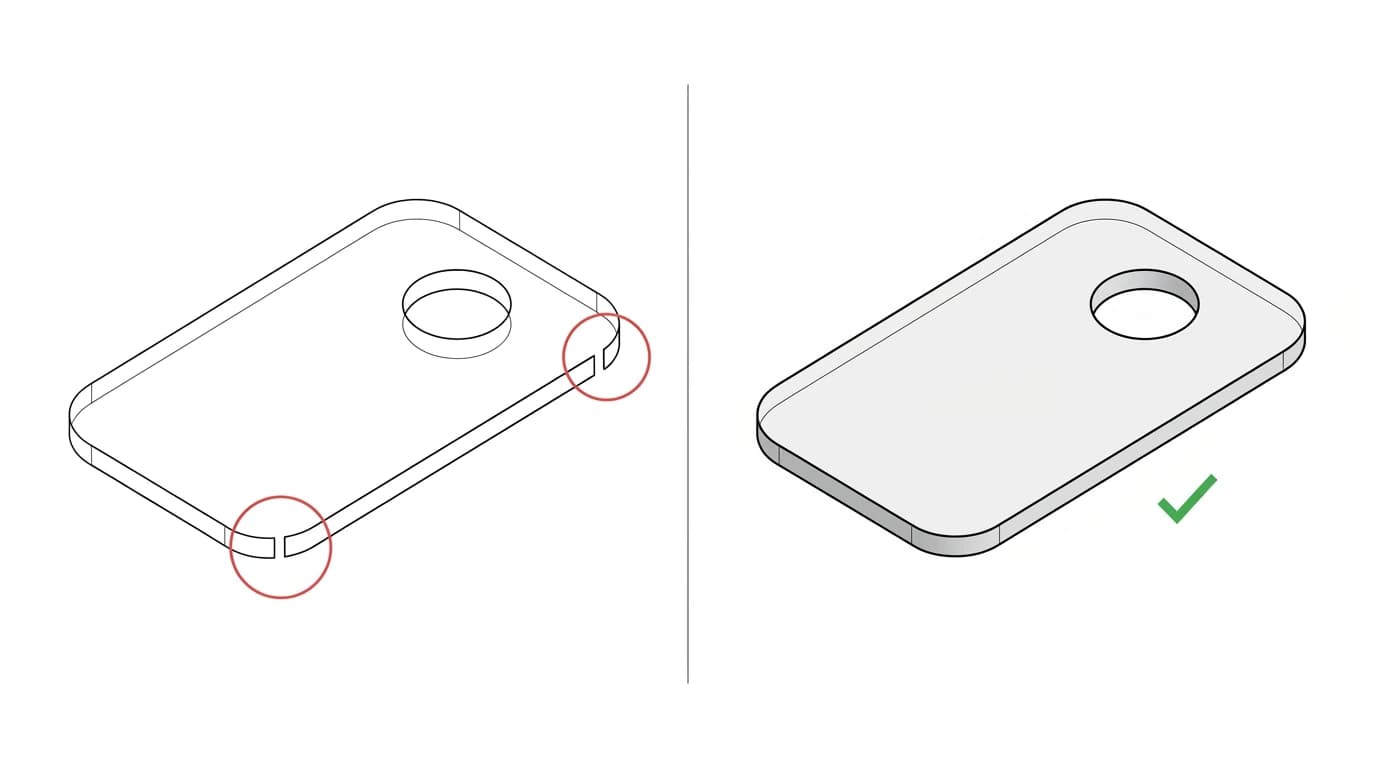
The file opens. The shape looks perfect on screen. You hit start, and the machine either does nothing, engraves a faint outline instead of cutting through, or spits out an error about an open path. It is one of the most frustrating moments in the whole workflow, because nothing looks wrong. Almost always the cause is invisible at a glance: your outline is not a single closed loop, it is a chain of pieces with a tiny gap in it. Here is how to see that gap and close it.
Our articles are still written by humans!
Get human written articles in your Google feed.
The short answer
A DXF that opens fine but will not cut is nearly always made of open paths rather than closed loops. A cutter needs a closed contour to know what is inside the cut and what is outside; an outline with a hairline gap has no inside, so the software skips it, engraves it, or errors. The fix is three steps: find the open paths and the duplicate lines with your software’s built-in tools, run a join or close command with a tolerance a little larger than the gaps, then confirm every profile is a single closed polyline before you cut. Do that and the same file that did nothing will cut cleanly.
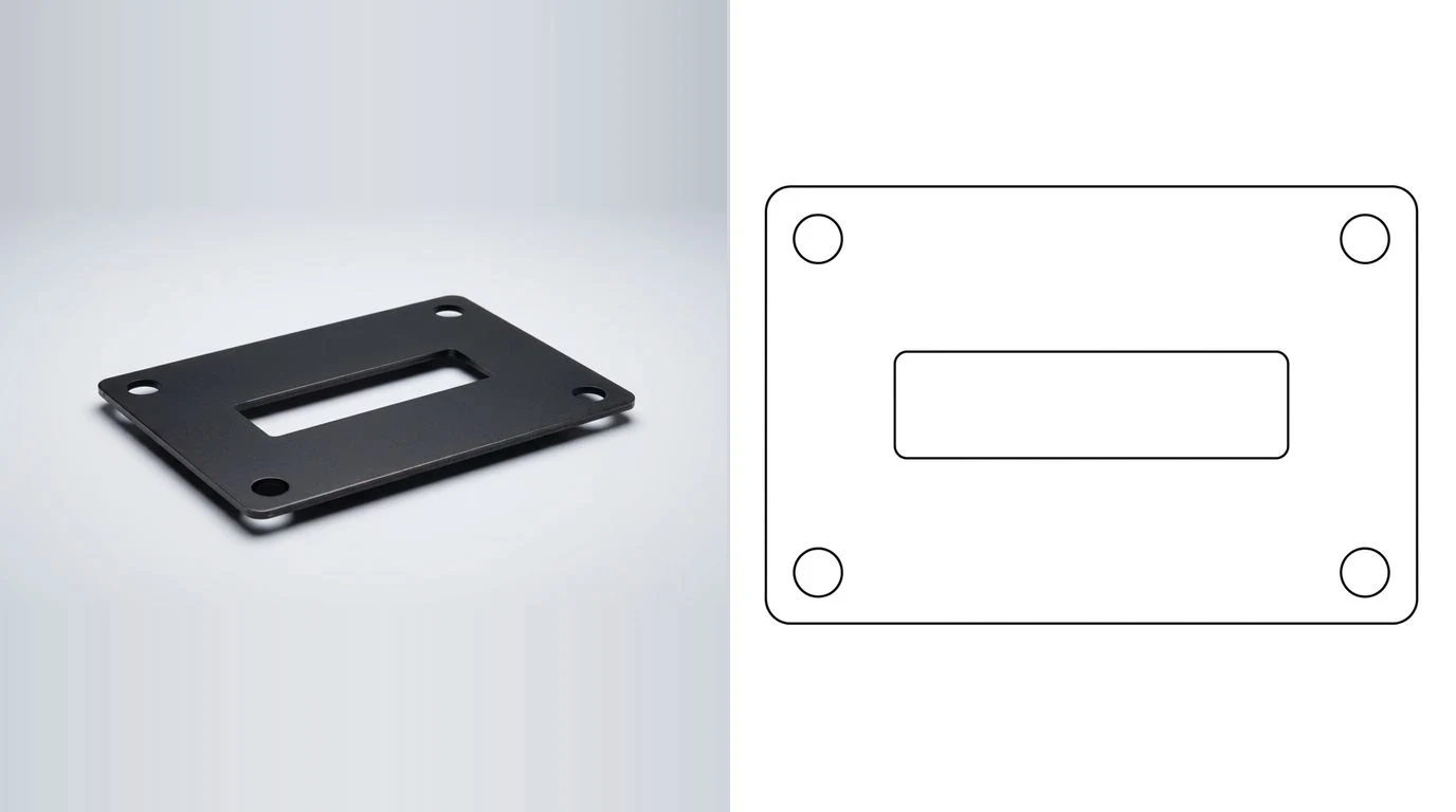
Open vs closed: the whole problem in one picture
Everything in this article comes down to one distinction. A closed path ends exactly where it started, so it forms a loop that encloses an area. An open path has two loose ends that do not quite meet, so it is just a line with a beginning and an end. Your eye cannot tell them apart when the gap is a hundredth of a millimetre, but the machine can, because it is reading coordinates, not pixels.
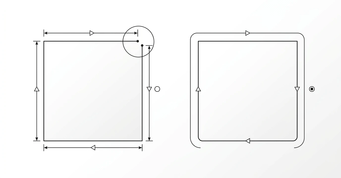
Why does a cutter care so much? Because a closed loop is the only way to define an inside. The machine cuts the boundary and the material inside drops out. An open path defines a boundary of nothing, so there is nothing to drop out, and most cut software refuses to treat it as a profile at all. That is the entire reason your file misbehaves.
What it looks like on the machine
Open geometry shows up in a few recognisable ways. If any of these sound familiar, you are almost certainly looking at a topology problem:
- Nothing happens. You start the job and the head does not move, or it moves but never fires. The software found no valid cut path.
- It engraves instead of cutting. You get a faint scored outline rather than a part that falls free, because the open path was treated as a line to mark.
- An open-path warning. Many tools pop a dialog offering to highlight or auto-close open shapes before cutting. That dialog is the answer, not an annoyance.
- The same edge cut twice. A doubled or scorched edge, longer run time, because two stacked lines were both cut.
The four things that break a cut file
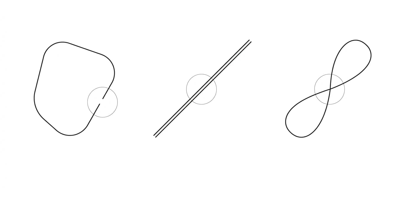
Strip it down and there are only four topology faults you will meet, and they often travel together in a traced or converted file:
1. Open contours
A profile made of segments whose ends do not connect into a loop. The classic case, and the one that stops a cut dead.
2. Gaps
A special, sneaky open contour: the path looks closed, but at one node the endpoints sit a tiny distance apart. Common at corners and where two arcs meet.
3. Overlapping or doubled lines
Two identical segments on the same coordinates, so the machine cuts the same edge twice. Usually left behind by tracing over geometry or by a converter that exports both an outline and a fill edge.
4. Self-intersections
A path that crosses itself, so the software cannot decide which side is inside. It may cut a stray sliver, invert a region, or refuse the shape outright.
How to find the bad geometry
You will not spot these by zooming in and squinting; the gaps are smaller than a pixel at normal zoom. Use the tools built for it:
- Show or select open paths. Most laser software has a command that highlights every unclosed shape. In LightBurn, open shapes render in a different colour and there is a dedicated selection for them.
- Delete duplicates. A one-click cleanup in most CAD and cut tools that collapses stacked lines to one. Run it before every cut.
- Node or vertex view. Turn on node editing and look at the suspect corners. Two nodes where there should be one means a gap.
- Overkill or purge. In AutoCAD-family tools, the
OVERKILLcommand removes duplicate and overlapping geometry in one pass.
This short walk-through from The Hope Yoder shows the close-path step in LightBurn on a real file, which is the exact move that turns most stubborn cut files around.
How to fix each problem
- Close the loops. Select the geometry and run join, close, or weld with a small tolerance so near-touching endpoints snap together. Set the tolerance a little above your gap size but well below your smallest real feature, so you do not fuse things that should stay apart.
- Remove duplicates. Run delete-duplicates or
OVERKILLto collapse stacked lines to one before cutting. - Break and rejoin self-intersections. Split the path at the crossing, delete the stray piece, and rejoin into a clean loop.
- Confirm closed polylines. Re-run the show-open-paths check. Nothing should be highlighted. Every cut profile should report as closed.
- Re-export as R12 DXF. Closed polylines, real units. This strips exotic entity types an older controller might drop.
The join command is the workhorse here, and the tolerance is the setting that matters. Too small and the gaps stay open; too large and separate features weld into each other. Start just above your largest visible gap and check the result. The commands by program: LightBurn Auto-join and Close Path, AutoCAD PEDIT then Close or JOIN, Illustrator Join, Inkscape node-join with the path set to closed.
Symptom to cause, at a glance
Match what the machine does to the fault behind it
How to stop it happening again
The cheapest fix is not creating the mess in the first place. A few habits remove most open-path grief:
- Prefer real geometry to auto-trace. Auto-tracing a bitmap produces the most fragments and the most gaps. Where you can, draw or generate clean vector geometry instead.
- Export closed polylines on purpose. Turn splines into polylines and make sure the closed flag is set on export.
- Run join and delete-duplicates as a habit. Make it the last two clicks before every export, not a rescue step after a failed cut.
- Start from a tool that outputs clean loops. If your input is a photo of a part, TechDraw AI produces a dimensioned 2D drawing whose profiles export as closed outlines, so you begin with cut-ready geometry rather than repairing a trace. The wider prep routine lives in how to prepare a DXF for laser cutting.
When it is not the contours
Closed loops fix the great majority of will-not-cut files, but be honest about the two problems that look similar and are not this:
- The file cuts, but at the wrong size. That is a units issue, not a topology one. The geometry is fine; the scale is off. Fix it with why a DXF imports at the wrong size.
- It cuts, but the edge is rough and faceted. That is smoothness, not closure. The loop is closed; it is just made of too many short segments. Clean it up with fixing a jagged vector trace.
Two different failures, two different fixes. This article is only about the third: whether the loops actually close. Get that right first, because a file that will not cut at all is a bigger problem than one that cuts slightly wrong.
Frequently asked questions
Why won't my DXF cut?
Nine times out of ten the geometry is not made of closed loops. A laser, waterjet, plasma or router follows a closed contour to know what to cut, and if a path has a tiny gap where its start and end points do not meet, the software treats it as an open line and either skips it, engraves it, or throws an error. The other common causes are two lines lying on top of each other, so the machine cuts the same edge twice, and paths that cross themselves. Fix the loops and the file cuts.
What is the difference between an open and a closed path in a DXF?
A closed path ends exactly where it began, forming a continuous loop with no gap, so it encloses an area. An open path has two loose endpoints that do not meet, so it is just a line or a chain of segments with a start and a finish. Cutting machines need closed paths because a closed loop defines an inside and an outside. An open path defines neither, so most cutting software will not cut it as a profile. Closing the loop is the single most important step in preparing a cut file.
How do I close open paths in a DXF?
In CAD or laser software, select the geometry and use a join, close, or weld command with a small tolerance, so endpoints that are almost touching snap together into one closed polyline. In LightBurn it is Edit then Auto-join or Close Path; in Illustrator it is Join; in AutoCAD it is PEDIT then Close or the JOIN command; in Inkscape you make sure nodes are joined and the path is closed. Set the join tolerance a little above the size of your gaps, but well below your smallest real feature.
Why does my laser engrave the outline instead of cutting through?
Because the software sees an open path, not a closed profile. Many laser tools will still trace an open path, but they treat it as a line to mark or engrave rather than a shape to cut out, so you get a scored outline instead of a part that drops free. The fix is to close the loop so it is recognised as a cut profile, then assign it a cut operation. If it still marks, check that the layer or colour is set to cut and not scan or engrave.
What are duplicate lines in a DXF and why do they matter?
Duplicate or doubled lines are two or more identical segments stacked on the same coordinates, usually created by tracing over existing geometry or by a converter that outputs both an outline and its fill edge. They matter because the machine cuts every path it is given, so it will run the same edge twice: wasted time, a scorched or widened kerf, and sometimes a small fire risk on flammable material. Run a delete-duplicates command before cutting to collapse them to a single line.
Why is a traced image full of open paths?
Because tracing tends to produce many small, separate line and arc segments rather than one continuous loop, and the segments often stop a hair short of meeting. Auto-traced bitmaps are the worst for this, since every pixel edge can become its own fragment. That is different from a jagged trace, which is about smoothness, not closure. If your outline looks rough as well as broken, the smoothing side is covered in cleaning up a jagged vector trace; here we are only concerned with whether the loops actually close.
Does the DXF version matter for cutting?
It can. Older machines and simpler laser controllers read some DXF versions better than others, and a very new DXF can carry entity types an older controller does not understand, which it may silently drop. Exporting an older flavour such as R12 DXF, with cut geometry as closed polylines rather than splines, is the safest bet for wide compatibility. Version is rarely the reason a file will not cut at all, though; open contours are far more often the culprit.