
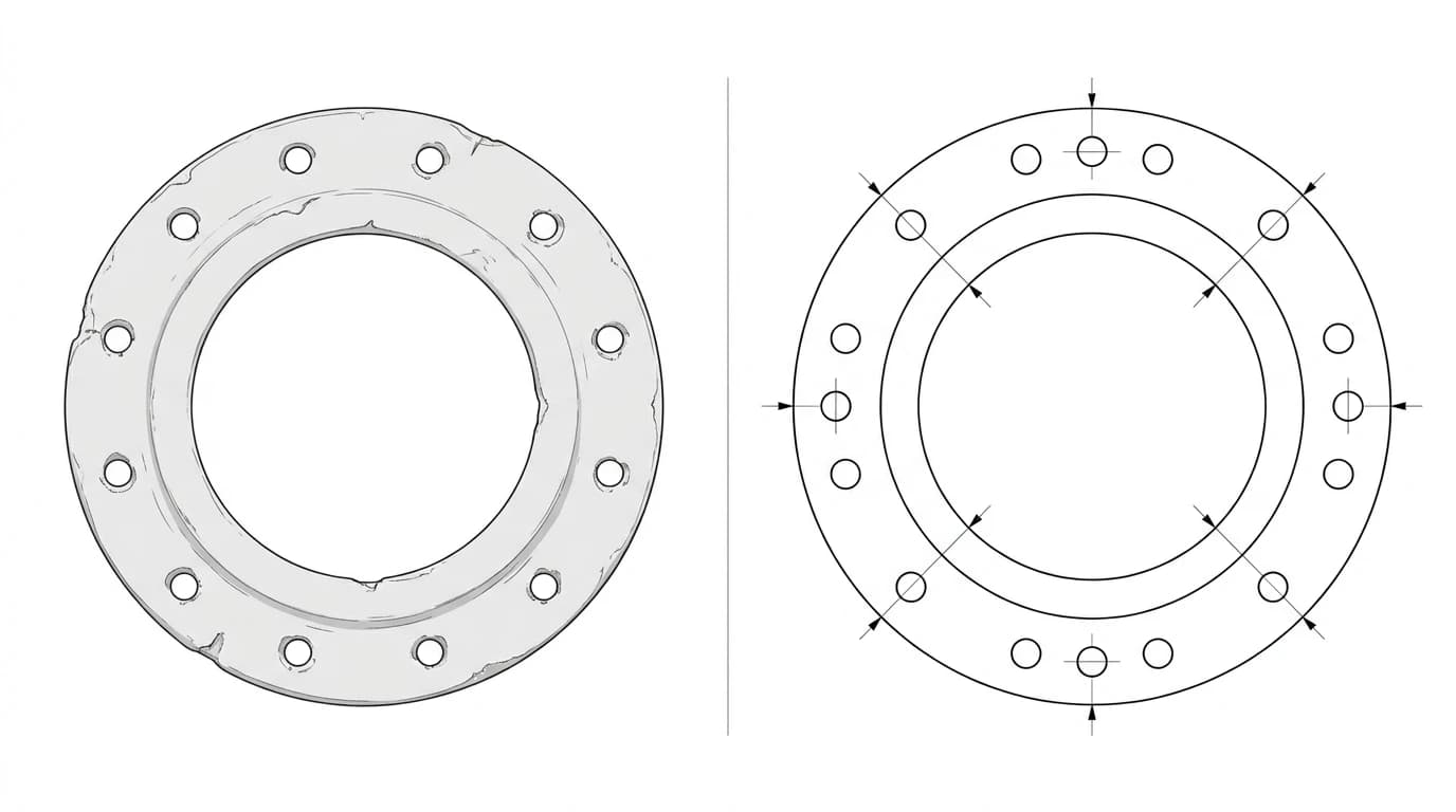
A gasket is about the friendliest thing there is to rebuild from a photo. It is flat, it is thin, and its whole job is described by an outline, a sealing hole and a bolt pattern. If the original tore, perished or never came with a drawing, you do not need one. Lay the old gasket down next to a coin, take one straight-down photo, and you have almost everything needed to trace a cut-ready DXF and have a fresh seal on the bench by the afternoon.
Our articles are still written by humans!
Get human written articles in your Google feed.
The short answer
To make a gasket DXF from a photo, do four things. One, lay the gasket flat and photograph it straight down with a coin or ruler beside it. Two, trace the outer edge, the centre bore and every bolt hole as separate closed outlines. Three, scale the whole drawing so the reference object measures its true size, which sets every other dimension in millimetres. Four, export a DXF with closed polylines and cut it on a laser, waterjet or gasket cutter. The part that trips people up is not the tracing, it is the scale, so that is where most of this guide goes.
Why a photo works so well for a gasket
Most parts are awkward to draw from a photo because they are three-dimensional. You photograph one face and the depth, the back, the hidden features are all guesswork. A gasket has none of that problem. It is essentially two-dimensional: a thin sheet whose thickness barely matters to the outline. Everything that defines the shape sits in a single plane and faces the camera at once. That is why tracing a gasket is closer to tracing a logo than to reverse-engineering a machined bracket. For the harder, three-dimensional cases, our guide on how to reverse-engineer a part covers the extra views you need, but a gasket rarely asks for them.
What a gasket DXF actually needs
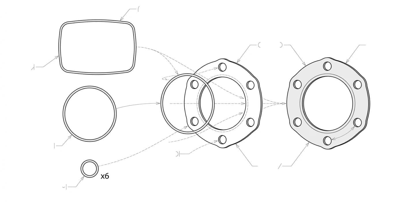
Strip away the noise and a gasket file is a small, well-defined thing. It holds three families of geometry, and each one has to be a closed loop so the cutter knows what is material and what is a hole:
- The outer profile. The overall shape, round, oval, rectangular or an irregular flange outline. It must stay inside the flange and cover the whole sealing face.
- The sealing bore. The central hole the fluid, gas or shaft passes through. This is the loop that most affects sealing, so it wants to match the port, not overshoot into the seal.
- The bolt holes. The ring of fastener holes. Position matters far more than perfect roundness here, because the gasket has to drop straight onto the studs.
If any of those loops is left open, with a tiny gap where the start and end points do not meet, a laser or router will not treat it as a cut. That single issue is the most common reason a gasket file fails on the machine, and it is worth its own read in why your DXF will not cut.
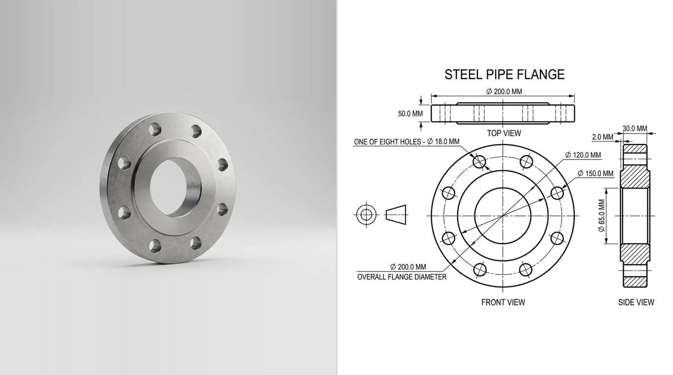
Get the size right: the reference trick
Here is the whole difficulty of the job in one sentence: a photo has no idea how big anything is. Two thousand pixels across could be a watch gasket or a manhole cover. You fix that by giving the photo a known length to measure against. Set a coin, a steel rule or a pair of calipers flat, in the same plane as the gasket, and shoot straight down. Because the reference and the gasket sit at the same distance from the lens, they share the same pixels-per-millimetre, so one known measurement unlocks every other dimension.
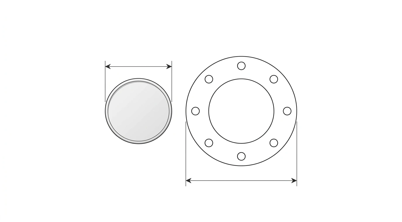
Some handy reference lengths, all easy to have on the bench:
Everyday reference objects and their true size
A steel rule laid across the gasket beats a coin, because you can read the real span of the part directly instead of trusting one small diameter. This is the same method covered in depth in how to get dimensions from a photo, and it is the single biggest factor in whether your finished gasket fits.
Photo to gasket DXF, step by step
- Clean and flatten the gasket. Wipe off oil, and if it is curled, press it flat under a book for a few minutes. A distorted gasket traces to a distorted outline.
- Add a reference and shoot straight down. Coin or rule flat in the frame, camera square above, even light, no harsh shadow across the edge.
- Trace the three loops. Outer edge, sealing bore, bolt holes. Keep each as its own closed outline.
- Scale to the reference. Set the known length to its true value so the whole drawing lands in real millimetres.
- Sanity-check the critical dimensions. Measure the bolt circle and the bore against the real part with calipers. Fix anything more than a fraction of a millimetre out.
- Export a DXF. Closed polylines, millimetres, R12 for the widest compatibility. Cut it.
You can do the tracing and scaling by hand in CAD, or let a tool do the heavy lifting. TechDraw AI takes a photo of a part and returns a dimensioned 2D technical drawing you export as DXF, which for a flat gasket means the outline, bore and bolt holes come back already drawn and ready to cut. If your starting point is a clean scan or image rather than a photographed object, the image to DXF converter traces it straight to vector, and converting a PDF to DXF covers the case where someone already sent you a drawing on paper. The general version of the photo route, for any part rather than a flat gasket, is JPG to CAD.
Two real examples
Below are two gaskets run through the exact photo-to-drawing pipeline this article describes: a photographed part in, a dimensioned 2D drawing out, the kind you export straight to DXF.
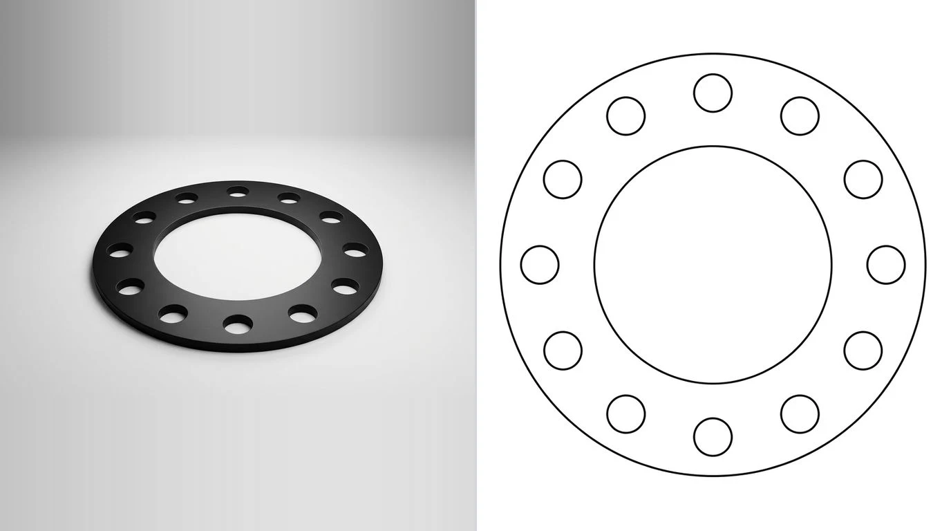
A round flange gasket
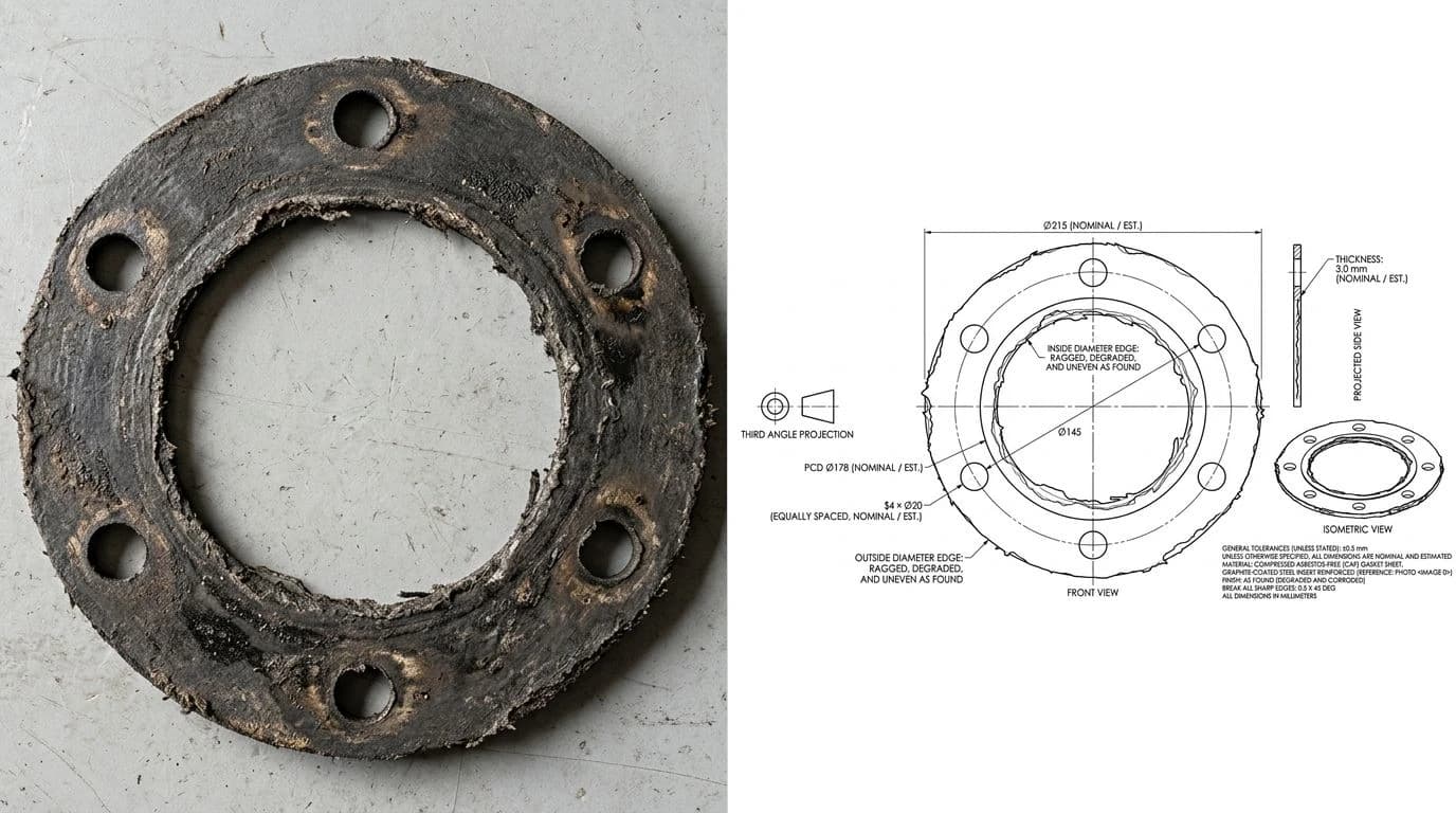
The round flange gasket is the textbook case, and its bolt pattern usually follows a standard. If you can identify the flange, the bolt circle diameter is likely published in a table such as ASME B16.5, which is a useful cross-check against what you measured off the photo.
An irregular cover gasket
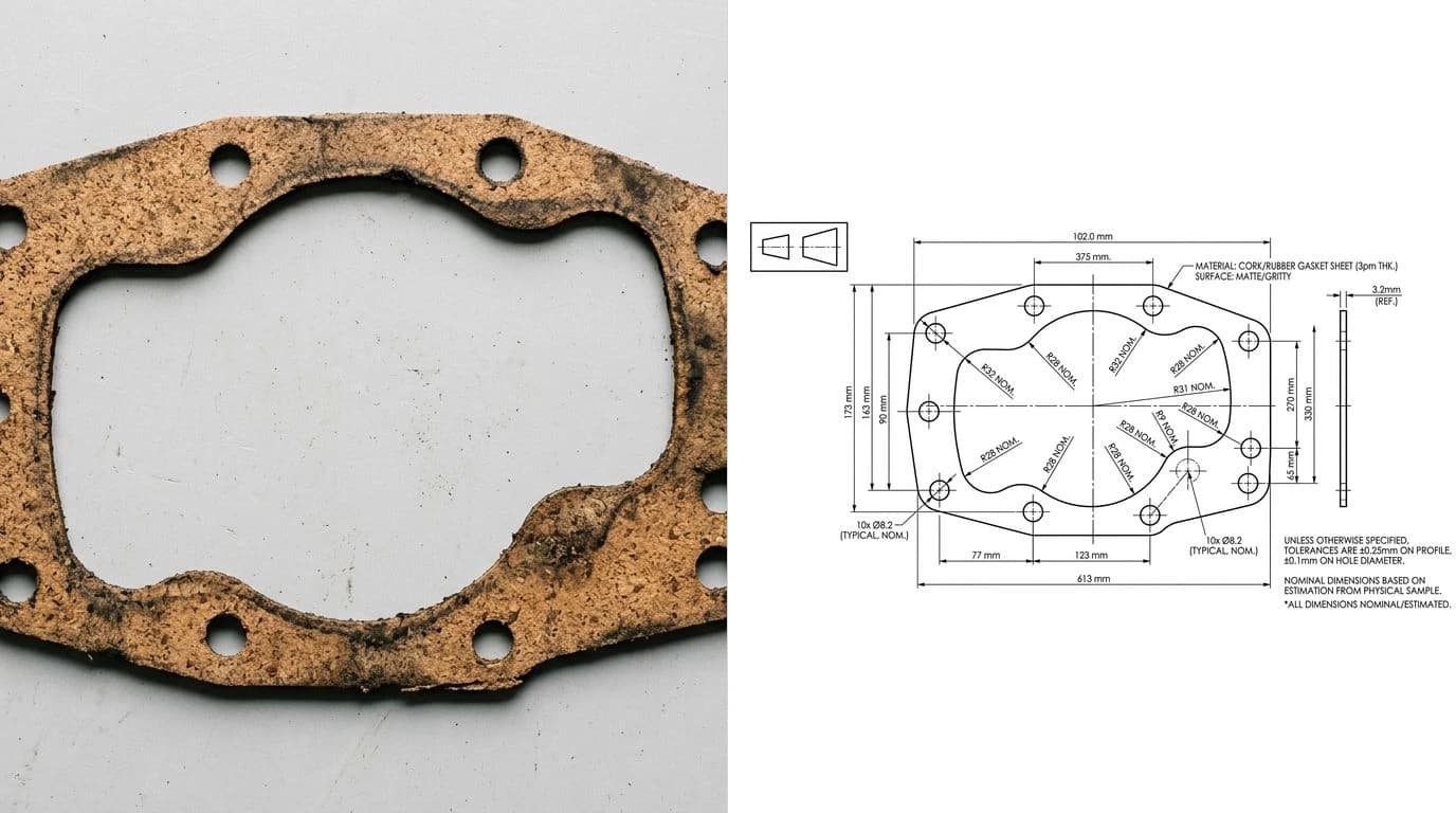
The irregular cover gasket, off a pump, a valve or an engine cover, is where photo tracing really earns its keep, because there is no catalogue to look it up in. The shape is whatever the casting is, so the photo and the reference object are your only source of truth. This is the same reverse-engineering approach we use for sheet metal drawings from a photo, minus the bends.
If you would rather watch the physical side of this done end to end, this short build from myfordboy laser-cuts his own gaskets from sheet and is a good feel for how the finished file turns into a real seal.
Bolt holes and hole patterns
Bolt holes are the part of a gasket most likely to make or break the fit, so they deserve a little extra care. Three things matter:
- Position over roundness. A bolt hole that is 0.5 mm out of round is fine. A bolt hole that is 2 mm out of position will not drop onto the stud. Measure the bolt circle diameter and the spacing, not just the hole size.
- Clearance, not interference. Draw the holes a touch larger than the bolt, typically 1 to 2 mm over, so the gasket slips on without fighting the studs.
- Use symmetry to your advantage. Most bolt patterns are evenly spaced on a circle. If you know the count and the bolt circle diameter, you can place them perfectly and let that correct small errors in the photo.
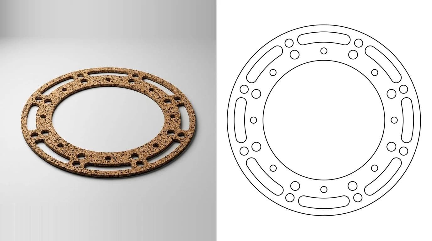
Pick the material and thickness
The DXF is the same shape no matter what you cut it from; the sheet you choose is a separate decision driven by the joint. A quick guide:
Common gasket materials by job
Thickness is worth confirming against the old gasket with calipers, because a cover that was sealed with a 1.5 mm gasket may leak or bind if you jump to 3 mm. The outline in your DXF does not change; you just order the right sheet.
Which cutter, which DXF
Almost any 2D cutting machine will make a gasket, and they all want the same thing from your file: a clean set of closed profiles in real units. The differences are about the material and the volume:
- Laser. The fastest route for thin rubber, fibre, cork and many gasket sheets. Follow the checklist in preparing a DXF for laser cutting. Watch ventilation with some rubbers.
- Waterjet. Handles thick, dense or reflective materials a laser struggles with, with no heat-affected edge.
- CNC router or drag knife. Good for softer sheet and larger one-off gaskets.
- Dedicated gasket cutter. A drag-knife plotter built for exactly this, fed the same DXF.
Whichever you use, export closed polylines and, if in doubt, an older R12 DXF. If it imports at the wrong scale, that is almost always a millimetre-versus-inch mix-up, and the fix is in why a DXF imports at the wrong size.
Five mistakes that ruin a gasket file
- Shooting at an angle. Perspective stretches the shape and skews the bolt spacing. Camera square, every time.
- No reference object. Without a known length the drawing has no scale, and eyeballing it means a gasket that does not fit.
- Open loops. A gap where an outline should close means the machine will not cut it. Confirm every profile is a closed polyline.
- Trusting a torn edge. If the original is damaged at a hole or the bore, trace the flange instead of inventing geometry.
- Bolt holes too tight. Give them clearance over the bolt so the gasket slides on. A hole cut exactly to bolt size fights the studs.
Frequently asked questions
Can I make a gasket from a photo?
Yes. A gasket is a flat 2D shape, which is exactly what a photo captures well, so you can trace a photo of an old or broken gasket into a cut-ready outline. The one thing a photo does not give you for free is scale, so lay a coin or a ruler flat next to the gasket in the same shot. That reference object lets you, or a tool, convert pixels into real millimetres. Once the outline, the centre bore and the bolt holes are drawn to size, you export a DXF and cut it.
How do I get the right size from a gasket photo?
Put a known object flat in the frame, in the same plane as the gasket: a coin, a steel rule, or calipers set to a round number. A US quarter is 24.26 mm, a Euro 2 coin is 25.75 mm, and a AA battery is 50.5 mm long. Because the reference and the gasket sit at the same distance from the camera, the pixels-per-millimetre they share lets you scale every dimension on the gasket from that one known length. Shoot straight down to avoid perspective distortion.
What file format do I need to cut a gasket?
A DXF, in almost every case. Laser cutters, waterjets, plasma tables, CNC routers and dedicated gasket cutters all follow a flat 2D profile, and DXF is the near-universal format for that. Export the outer edge, the centre bore and every bolt hole as closed polylines in real millimetres, and an older flavour like R12 DXF is the most widely accepted. If the shop asks for a vector PDF or SVG instead, the same closed-outline geometry exports to those too.
How do I make a replacement gasket without the original drawing?
You reverse-engineer it from the part you have. Photograph the old gasket flat, next to a coin or ruler, or if it is torn, photograph the mating flange face and its bolt pattern instead. Trace the outer profile, the sealing bore and the bolt holes, scale everything from the reference object, then export a DXF. This is the same reverse-engineering logic used for any part with no paperwork, just applied to a thin flat seal.
What material should a custom gasket be?
It depends on what it seals and how hot it gets. Nitrile (NBR) rubber suits oil, fuel and water up to about 100C. Fibre or compressed non-asbestos sheet handles higher heat and pressure for engine and flange joints. Cork or cork-rubber suits low-pressure covers like valve and inspection covers. PTFE handles aggressive chemicals. The DXF you cut is the same shape regardless; you just choose the sheet and thickness to match the joint, usually 0.5 to 3 mm thick.
Can a gasket be laser cut?
Yes, and it is one of the most common ways to make one. A laser cuts a clean, repeatable profile from rubber, fibre, cork and many gasket sheets, following the closed 2D outline in your DXF. Very thick or highly reflective materials are better suited to a waterjet or a die, and some rubbers smell strongly when lasered, so ventilation matters. For thin sheet gasket material under a few millimetres, a laser is usually the fastest route from DXF to finished seal.
How accurate does a gasket outline need to be?
The bolt holes and the sealing bore need to be accurate, the outer edge much less so. If the bolt-hole positions are off by even a millimetre or two, the gasket will not drop onto the studs, and if the bore is too small it blocks flow or too large it intrudes into the seal. The outer edge just has to stay inside the flange and cover the sealing face, so a small error there is harmless. Prioritise the holes and the bore when you check the drawing.