A sheet metal part lives a double life. On the bench it is a folded bracket or enclosure; on the cutting table it is a single flat shape with a few fold lines. A drawing that goes to a fabricator has to carry both, and the bridge between them, the flat pattern, is where most home-made sheet metal drawings go wrong. Here is what the drawing actually needs to show, what you can pull straight from a photo, and what you have to add yourself.
What a sheet metal drawing actually shows
A useful sheet metal drawing answers two separate questions for the shop. First, what is the finished part: the formed views with overall dimensions, hole positions, bend angles and a note of the material and thickness. Second, what do I cut: the flat pattern, the unfolded outline with every hole and cut-out, which is what the laser, punch or waterjet drives along. The first is for understanding and inspection; the second is the file the machine runs. Get either one wrong and the part comes back wrong.
This is the one way sheet metal differs from a solid machined part. With a milled block, the drawing and the stock are the same shape. With sheet metal, the drawing describes a 3D object but the machine cuts a 2D blank that looks nothing like it until it is folded. If you are new to reading either view, our guide to how to read a technical drawing covers views, projection and the title block.
Flat pattern vs formed part
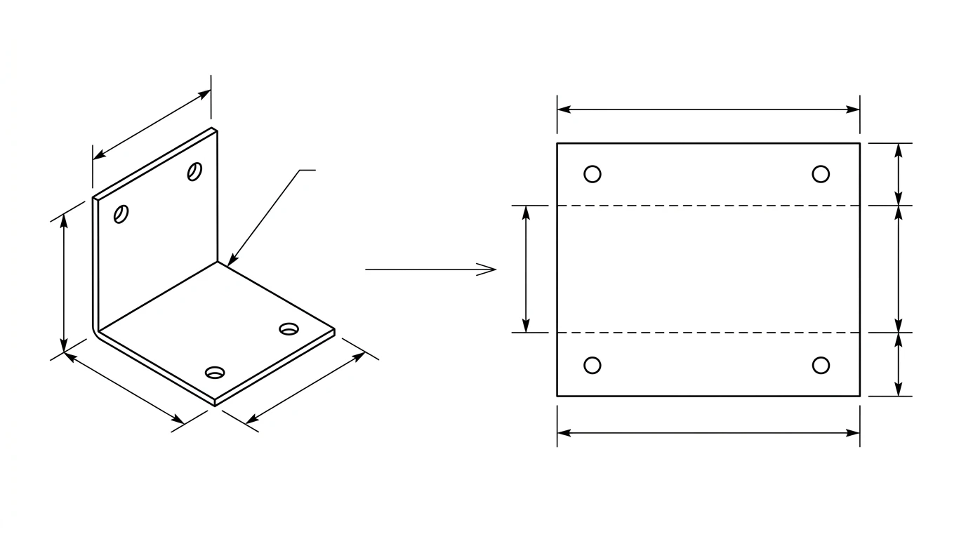
The formed part is the bracket in its final shape. The flat pattern is that same bracket unfolded flat, as if you peeled every bend back to 180 degrees. The flat pattern is the only geometry the cutting machine cares about, because you always cut first and bend second.

The trap is assuming the flat length is just the sum of the visible sides. It is not. When metal bends, the outside of the bend stretches and the inside compresses. Somewhere between them sits a layer that does neither, the neutral axis, and the true flat length is measured along that line. So a 100 mm by 100 mm L-bracket made from 2 mm steel does not unfold to 200 mm; it unfolds to slightly less, because the bend swallows a little material. That difference is the bend allowance, and ignoring it is the single most common reason a home-made flat pattern comes out a few millimetres off.
Bend allowance and K-factor, briefly
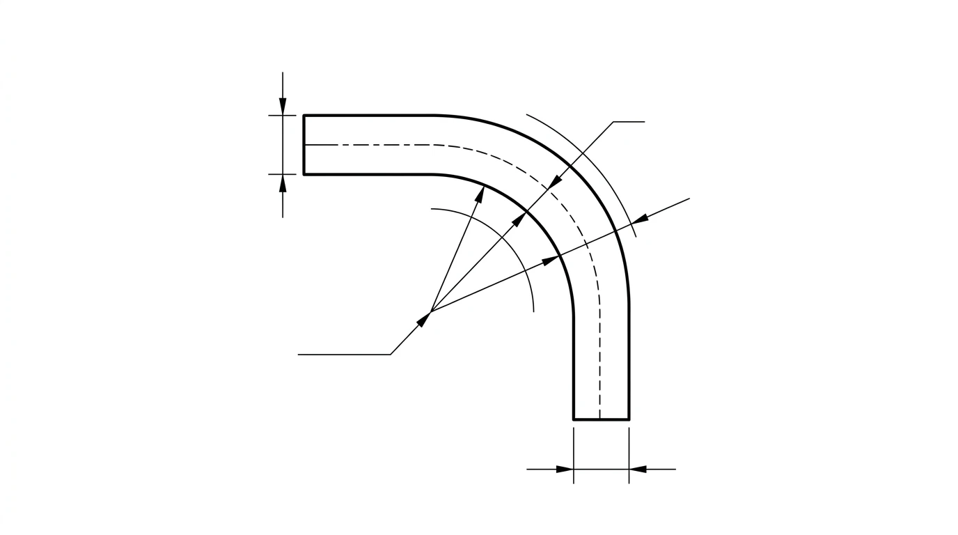
You do not have to derive these by hand, but you should know what they mean so you can ask your shop for the right number. The bend allowance (BA) is the length of the neutral axis through a single bend:
BA = angle (radians) × (R + K × T)where
R is the inside bend radius, T is the material thickness, and K is the K-factor.The K-factor locates that neutral axis as a fraction of the thickness. A K-factor of 0.4 means the neutral axis sits 40 percent of the way through the metal from the inside face. In practice it falls between roughly 0.3 and 0.5, commonly around 0.33 to 0.44 for mild steel, and it depends on the material, the radius and how the shop forms the part. This is exactly why you ask: a fabricator works to a K-factor they have dialled in for their press brake and tooling, and using their value is what makes your flat pattern match their finished part.
A concrete example: a 90 degree bend in 2 mm steel with a 2 mm inside radius and a K-factor of 0.4 consumes a bend allowance of about 4.4 mm of material (1.571 × (2 + 0.4 × 2)). One bend hides that error; across four or five bends it stacks up into a part that does not fit.
What a photo can, and can't, give you
A photo is an excellent starting point for the parts of a sheet metal drawing that are about shape and position, and a poor one for the parts that are about fold mathematics. Knowing which is which saves you from expecting the impossible.
What a clear, square-on photo gives you reliably:
- The outline of a flat part, or of any single face, as a clean closed profile.
- Hole and slot positions and their pattern across the face.
- Proportions and overall dimensions, once you anchor one known measurement for scale.
- Cut-outs, notches and corner reliefs on the face you photograph.
What a single photo cannot give you on its own:
- The unfolded flat length of a bent part, because that needs the thickness and bend radius you cannot read from a picture.
- Bend angles to the degree, unless the part is sitting square to the camera or you measure them.
- Material thickness, which you measure with calipers, not eyes.
So the honest workflow is: use the photo to nail the geometry of each face, the holes and the outline, then supply thickness and bend information so the flat pattern can be built correctly. For a flat part with no bends, the photo alone is enough to produce a finished, cuttable drawing. This is the same divide we cover in reverse engineering a part and image to CAD: a photo captures shape, your calipers capture the dimensions that matter.
Photo to a sheet metal DXF, step by step
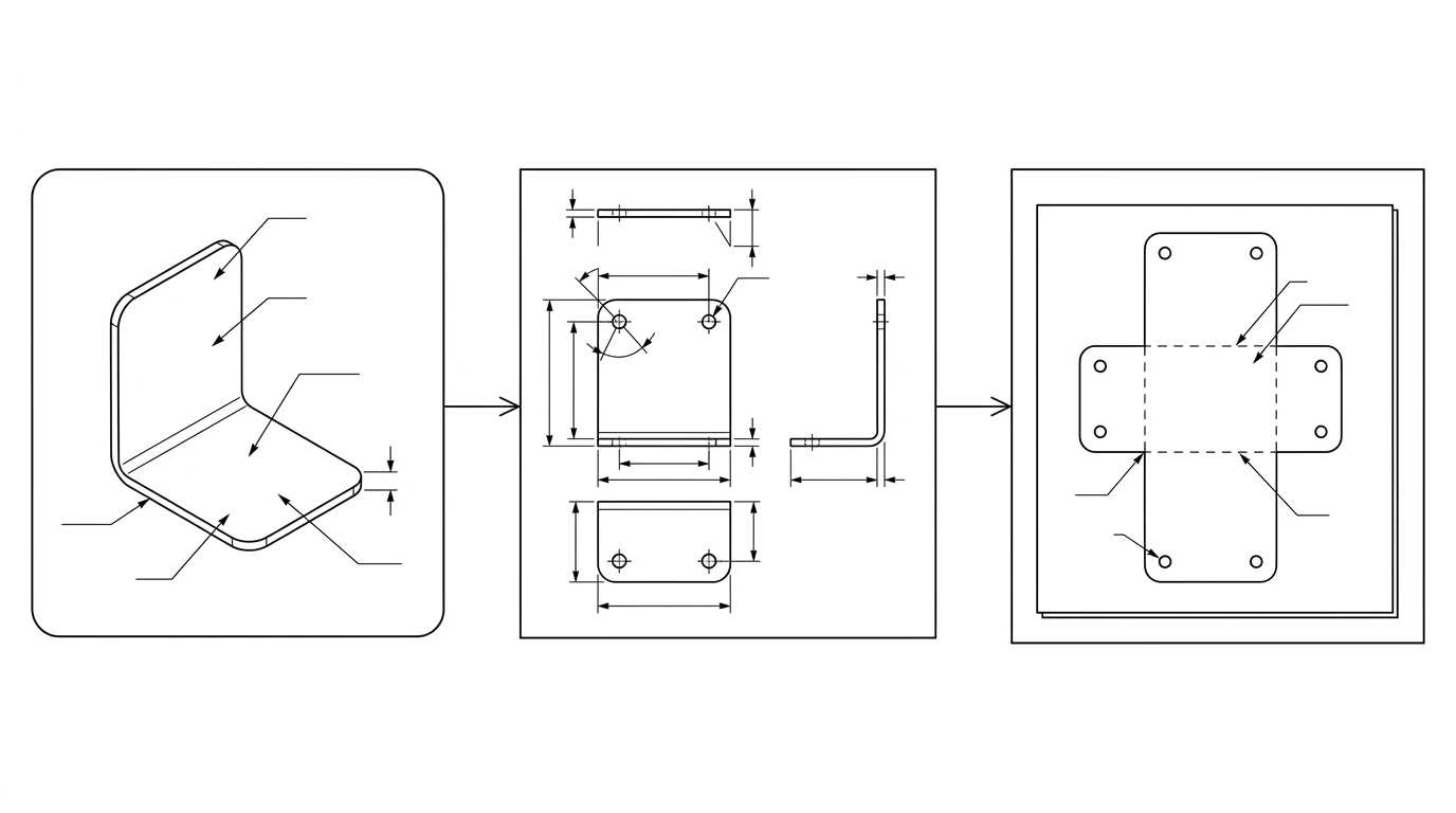
- Photograph the face square-on. Lay the part flat, shoot straight down with even light, and keep the camera parallel to the face so the outline is not distorted. Put a ruler or a coin in frame for scale.
- Measure the anchors.With calipers, record the thickness, one overall dimension, and the diameter of one hole. These turn the photo's proportions into real dimensions.
- Generate the 2D drawing. Upload the photo to TechDraw AI, set the known dimension to fix the scale, and get a dimensioned outline of the face with its holes and cut-outs.
- Handle the bends. For a flat part you are done. For a bent part, note each bend line, angle and the inside radius, and either send those to the shop or use them to unfold the flat in sheet metal CAD.
- Export a DXF of the flat pattern with the cut outline and holes as closed paths, then check the scale against your known dimension before sending.
Material, gauge and bend notes to include
Geometry is only half a sheet metal drawing. A fabricator also needs the notes that geometry cannot show:
- Material and thickness.“1.5 mm 304 stainless” or “16 gauge mild steel”. Gauge is ambiguous across materials, so give the millimetre or inch thickness too.
- Bend lines, angles and direction. Mark each bend, its angle, and whether it folds up or down relative to the face you drew.
- Inside bend radius.State it, or note “shop standard” and let them pick the tooling.
- Hole sizes and tolerances. Call out any hole that must take a fastener or press-fit, since punched and laser holes vary slightly.
- Finish and grain direction if they matter, for example a brushed face or bends that must run with the grain.
For how to place those dimensions so they read cleanly, see how to dimension a technical drawing, and for what separates a sketch from a file a shop will actually run, what makes a drawing manufacturing-ready.
Making the flat pattern laser or punch ready
The flat pattern is cut on the same machines as any other 2D profile, so the same file rules apply. The cut outline and every hole must be closed vector paths, the units must be set and stated so the part is not scaled by a factor of 25.4, and bend lines belong on their own layer so the machine does not try to cut them. Our guide to preparing a DXF for laser cutting covers closed paths, units, duplicate lines and layers in full, and if a file comes in the wrong size, why a DXF imports at the wrong scale walks through the fix. If you are sending a flat blank straight to a CNC router or plasma table instead, the same closed-path rules from sketch to a CNC-ready DXF apply. For whether to send DXF, DWG or STEP in the first place, see DWG vs DXF.
The pre-flight checklist
Before a sheet metal job leaves your hands:
- Flat pattern outline and holes are closed paths; bend lines are on a separate layer.
- Flat length accounts for bend allowance, not just the sum of the sides.
- Material and thickness stated in real units, not gauge alone.
- Each bendhas an angle, direction and inside radius (or “shop standard”).
- Units set and stated, with one known dimension checked against the file.
- Fastener and press-fit holes carry a tolerance.
Tick those off and your part folds up to the size on the drawing, which is the whole point. Start by turning your photo into a clean dimensioned outline with TechDraw AI, then add the bend and material notes above.
Frequently asked questions
Can you make a sheet metal drawing from a photo?
Yes, for the part you can see. A photo gives you the outline, hole positions and proportions, which is enough to produce a dimensioned 2D drawing of a face or of a flat blank. What a single photo cannot give you on its own is the unfolded flat length of a bent part, because that depends on the material thickness and bend radius. For a flat part, or once you supply thickness and bend details, a photo is a fast, accurate starting point.
What is a flat pattern in sheet metal?
A flat pattern is the part unfolded into a single flat shape, the way it looks before any bends are made. It is the outline the laser, punch or waterjet actually cuts from the sheet. Because metal stretches slightly at each bend, the flat pattern is not simply the sum of the side lengths; it is calculated using the bend allowance.
What is bend allowance and K-factor?
Bend allowance is the extra length of material consumed inside a bend. It is calculated from the bend angle, the inside radius, the material thickness and the K-factor. The K-factor is the position of the neutral axis, the layer that neither stretches nor compresses, expressed as a fraction of the thickness. It typically falls between 0.3 and 0.5, around 0.33 to 0.44 for mild steel, and your shop can tell you the value they use.
What file format do sheet metal shops want?
Almost all sheet metal cutting runs from a DXF of the flat pattern, with the cut outline and holes as closed vector paths and bend lines kept on a separate layer. Some shops also accept DWG or a STEP file of the 3D model. DXF of the flat pattern is the most universal and the safest to send.
Do I need CAD to get a sheet metal drawing?
Not for a flat part or a single face. You can photograph it, generate a dimensioned 2D drawing and export a DXF without opening CAD. For a bent part where you need the exact flat length, you either supply the thickness and bend radius so the flat can be calculated, or unfold the part in sheet metal CAD. The drawing of each face still starts cleanly from a photo.