The first time you open a technical drawing it looks like noise. Views, numbers, arrows, odd little symbols and a grid of boxes in one corner. None of it is decoration. A drawing is a precise instruction set, and the only reason it feels confusing is that nobody told you the order to read it in. Learn that order and the whole sheet goes quiet.
Start in the corner, not the middle
Almost everyone starts in the centre of the page, where the part is. That is the wrong place. Start in the title block, the boxed grid usually parked in the bottom right corner. It is the legend for everything else on the sheet, and four of its fields change how you read every number on the page.
- Units. Millimetres or inches. A value of 12 means very different parts depending on this one field.
- Scale. The ratio between the drawing and the real part, such as
1:2or2:1. Scale is for printing and proportion only. You never measure a printout with a ruler to get a size, which is exactly why most drawings carry aDO NOT SCALE DRAWINGnote. - Drawing standard. ISO, ASME or DIN. The standard governs how symbols and tolerances are interpreted.
- Projection method. First-angle or third-angle, shown as a small symbol. More on this below, because getting it wrong can flip the part.
The title block also holds the part number, the revision letter, the material, the finish, the sheet count and the names of whoever drew and checked it. Read it like the front matter of a contract, because that is what a drawing is. We make that case in full in why machine shops still want 2D drawings.
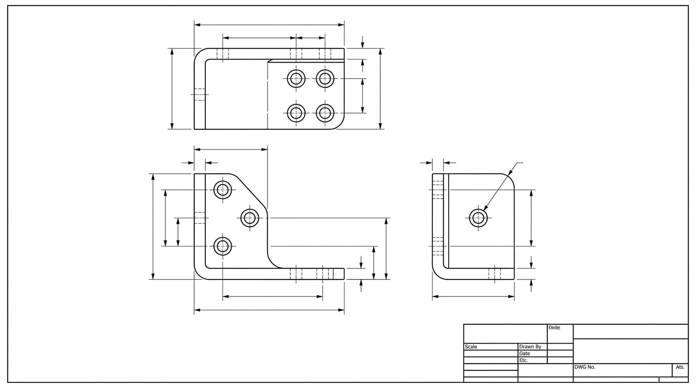
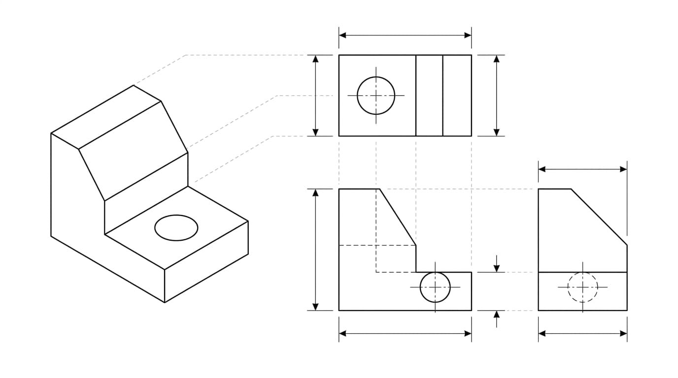
The views are one object seen from several directions
The pictures in the middle are not different parts. They are the same object viewed straight on from different sides, a method called orthographic projection. Most drawings show a front view, a top view and a side view. The front view is chosen as the most descriptive face of the part, and the others are arranged around it.
A few line conventions do a lot of quiet work here:
The line types you see on a technical drawing
| Line | Name | What it means |
|---|---|---|
| Visible edge | A solid thick line: an edge you can actually see | |
| Hidden edge | A dashed line: a feature behind the surface you are looking at | |
| Centre line | A thin long-short-long chain line: the centre of a hole or an axis of symmetry | |
| Section hatching | Diagonal hatching: solid material that has been cut through in a section view |
When a feature is too small or too crowded to dimension in place, the drawing pulls it out into a detail view at a larger scale, labelled with its own letter. Section and detail views are helpers, not new information you have to reconcile.
Check the projection symbol before you trust a layout
This is the single most common beginner mistake, and it can mirror a whole part. There are two ways to arrange the views, and they place the same faces in opposite positions.
- Third-angle projection is standard in the US and Canada. The views sit where you would expect if you walked around the part: top view above the front, right view to the right.
- First-angle projection is common across Europe and Asia. The layout is mirrored: the top view drops below the front, and the right view lands on the left.
The drawing tells you which is in use with a small symbol of a truncated cone, usually in or near the title block. If you read a first-angle drawing with third-angle habits, you can build the mirror image of the intended part. Check the symbol first, every time, on any drawing whose origin you are not sure of.
Every number has a tolerance, stated or implied
A dimension is more than a size. A complete dimension callout has a nominal value (say 12.00) and a tolerance, the amount it is allowed to vary. Tolerance shows up in a few forms:
- Plus or minus, like
12.00 ±0.05, meaning anything from 11.95 to 12.05 is acceptable. - Limit dimensions, where the upper and lower sizes are written directly, such as a top number of 12.05 over a bottom number of 11.95.
- Unequal (unilateral), like a feature allowed to grow but not shrink.
Here is the part beginners miss. If a dimension has no tolerance written next to it, it is not perfect or free. It inherits the general tolerance from the title block, which almost always points to a standard like ISO 2768-m. That standard assigns a permitted variation based on the size of the feature, so a plain 40 still has a defined acceptance range. A number in square brackets is a reference dimension, shown for convenience and not toleranced or inspected.
Which dimensions matter, and how they should be laid out, is a craft of its own. We cover the rules in how to dimension a technical drawing. And to decode the tolerances themselves — the ± values, limit dimensions and fit callouts like ⌀13 H7/g6 — see how to read tolerances on a drawing.
The symbols that trip up beginners
You do not need to memorise a dictionary. A handful of symbols cover most of what you will meet:
The everyday symbols you meet when reading a drawing
| Symbol | Name | What it means |
|---|---|---|
⌀ | Diameter | ⌀ 12 is a 12 unit diameter, not a radius |
R | Radius | R6 is a 6 unit radius |
± | Plus or minus | The tolerance allowed on a dimension |
° | Degrees | An angular dimension, such as a chamfer or draft angle |
□ | Square | A square feature; one value covers both sides |
M8×1.25 | Thread callout | A metric (or imperial, 1/4-20 UNC) thread spec a photo can never reveal on its own |
Ra 3.2 | Surface finish | Allowed roughness, usually shown with a tick symbol and a value |
Then there is GD&T, the symbols inside small rectangular boxes called feature control frames. They control geometry, for example how true the position of a hole pattern must be relative to a reference surface. GD&T is a real skill, but it is a layer you can add later. Recognise the boxes, know they mean a geometric requirement, and keep reading. When you are ready for that layer, our guide to engineering drawing symbols and GD&T walks through every one.
Notes are not optional reading
The block of text, usually top left or beside the title block, is where the requirements live that no dimension can express. Material grade and condition. Surface treatment and plating. Deburring and edge breaks. Heat treatment. The default tolerance standard. Inspection requirements.
Skimming the notes is one of the most expensive habits in manufacturing. A missed plating note, a missed thread class, a missed finish callout, and the part is technically made yet functionally wrong. Read every note before you quote a part or cut metal. For the full picture of what a complete sheet should contain, see what makes a drawing manufacturing-ready.
A reading order you can reuse on any drawing
Put it together and you have a routine that works on a bracket, a bearing housing or a piece of furniture:
- Read the title block: units, scale, standard, projection, material, revision.
- Scan the views and identify the front view and how the part sits.
- Confirm the projection angle from the symbol so you read the layout correctly.
- Read the overall dimensions first, then work inward to individual features.
- Read every note, not just the ones near a dimension you care about.
- Check tolerances on the features that matter for fit and function, and assume the general tolerance everywhere else.
- Follow any section and detail views to understand internal features.
A drawing rewards patience in a way a 3D model does not. Once you read in this order a few times it stops being a wall of symbols and starts being a clear set of instructions, which is all it ever was. If you are going the other direction and need to make a technical drawing rather than read one, that guide walks the same steps in reverse, or start from a photo with our photo to technical drawing walkthrough.
Frequently asked questions
What is the first thing you should read on a technical drawing?
The title block, usually in the bottom right corner. It tells you the units, the scale, the drawing standard and the projection method. None of the numbers on the sheet mean anything until you know those four things, so the title block always comes first.
What is the difference between first-angle and third-angle projection?
They are two conventions for arranging the same views. In third-angle projection (standard in the US and Canada) the top view sits above the front view and the right view sits to the right. In first-angle projection (common in Europe and Asia) the layout is mirrored: the top view sits below and the right view sits to the left. A small truncated-cone symbol in the title block tells you which one is in use.
What does the diameter symbol look like on a drawing?
It is a circle with a diagonal line through it, written as ⌀. A value like ⌀ 12 means a 12 unit diameter, not a radius. Radius is written with a capital R, so R6 means a 6 unit radius.
What happens if a dimension has no tolerance written next to it?
It is not exact. It falls back to the general tolerance block in the title block, which usually points to a standard such as ISO 2768. That standard sets a permitted plus or minus value based on the size of the feature, so a dimension with no individual tolerance still has a defined acceptance range.
Do I need to understand GD&T to read a drawing?
Not for most drawings. You can read the large majority of parts with views, dimensions, the common symbols and the notes. GD&T (the symbols inside rectangular boxes) is a deeper layer used where the geometric relationship between features matters. You can learn to recognise it later without it blocking you now.