A technical drawing is not a picture of a part; it is a set of instructions for making one. Get it right and a shop you have never met can build the part to size, first time, without a single phone call. Get it wrong and you pay for guesses. The good news is that a manufacturing drawing is built the same way every time, in a fixed order, whether you draw it by hand, in CAD, or hand the first draft to an AI tool. This guide walks through that order, step by step.
What the drawing actually has to do
Before any lines go down, be clear on the job. A manufacturing drawing has to communicate, without ambiguity, everything a maker needs to turn raw material into your part: its shape, its exact sizes, how much each size is allowed to vary, what it is made of, and how the surfaces should finish. Anything the reader has to assume is a place the part can come back wrong.
That is why drawings follow shared conventions and standards such as ISO 128 for how a drawing is presented and ASME Y14.5 for dimensioning and tolerancing. You do not need to memorise them, but you do need to respect what they exist to protect: a drawing should read the same way to everyone, in every shop. If you are not yet fluent in how one is laid out, our guide to how to read a technical drawing is the mirror image of this one and worth a look first.
Step 1: Start from the part, not the page
Every drawing starts from a source of truth about the geometry. You have one of three:
- A 3D CAD model. The cleanest start. The views and most dimensions can be projected straight from the model.
- A physical part. You are documenting something that already exists, so you will measure it with calipers and a rule. This is reverse engineering, and the drawing is the deliverable.
- A sketch or a photo. The idea exists only on paper or in a snapshot. You need to turn that into measured geometry before you can dimension anything.
Whichever you have, decide up front the units (millimetres or inches) and the rough scale the part will be drawn at, and pick the front view: the face that shows the most about the part and that the others will be built around. Getting the front view right makes the rest of the layout fall into place. If your starting point is a photo, our photo to manufacturing drawing walkthrough covers turning that snapshot into real geometry.
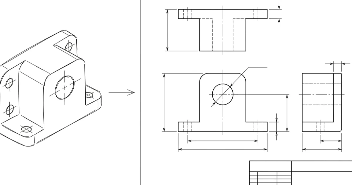
Step 2: Lay out the views
A technical drawing flattens a 3D part into a set of 2D orthographic views, each looking straight at one face. Most parts need three, front, top and side, but the rule is simpler than a fixed number: use the fewest views that show every feature clearly, and no more. A flat plate may need only one; a complex housing may need five plus sections.
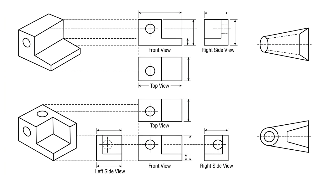
Choose the projection convention
The views are arranged by either first angle (common in Europe and much of the world) or third angle (the norm in the US and Canada). The two mirror each other, so a drawing read in the wrong convention can be machined back to front. You may use either, but you must declare which with the projection symbol in the title block.
Add sections and details where needed
When internal features, a bore, a pocket, a counterbore, would otherwise be drawn as confusing hidden lines, cut a section view to reveal them, and add an enlarged detail view for anything too small to dimension at the main scale. A single clear isometric view in a corner also helps the reader picture the part, though it is not dimensioned.
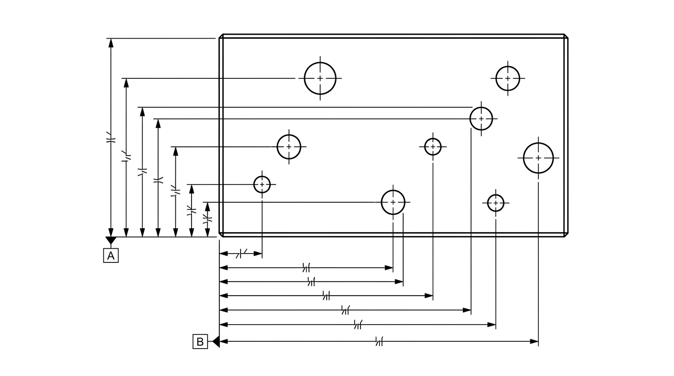
Step 3: Dimension it
This is where most drawings are won or lost. The goal is to fully define the part, every size and position present, while defining each feature exactly once. Dimension a feature twice and the two values will eventually disagree after an edit, leaving the shop to guess which is right.
- Work from a datum. Measure features from a common reference edge or face rather than chaining them end to end, so small errors do not stack up across the part.
- Dimension the function. Call out the sizes that make the part work, the hole spacing that has to match a mating part, not whatever was easiest to measure.
- Do not over-dimension. Redundant dimensions are a defect, not extra safety.
This step has its own rules and its own failure modes, so it has its own guide: see how to dimension a technical drawing for datum strategy, baseline versus chain dimensioning, and the mistakes to avoid.
Step 4: Add tolerances
No part is made perfectly to size, so every dimension carries a tolerance, a band it is allowed to vary within. The skill is spending precision only where it earns its keep, because a tighter tolerance costs real money to hold.
- Set a general tolerance for the bulk of the dimensions with a standard such as ISO 2768, stated once in or near the title block, so you are not annotating every number.
- Tighten only the critical features individually: mating diameters, bearing fits, sealing faces. These get their own tolerance, called out on the dimension.
- Reach for GD&T when a simple plus-or-minus cannot capture what you need, for example flatness, position or concentricity. Our engineering drawing symbols and GD&T guide decodes the feature control frames.
Step 5: Add material, finish and notes
Geometry and tolerances describe the shape; the annotations describe what it is. A drawing that is dimensionally perfect but silent on material is still unbuildable. Add:
- Material and, if it matters, the specific grade or temper, for example a particular aluminium or steel spec.
- Surface finish where it is functional, given as a roughness value, plus any coating, plating or heat treatment.
- Thread callouts for holes that are tapped, and chamfer or deburr notes on edges.
- General notesfor anything that applies across the part: “break all sharp edges”, finish, inspection requirements.
Step 6: Fill in the title block
The box in the bottom-right corner looks like paperwork, but it carries the information that stops expensive mistakes. At a minimum it should state:
- Part name and number, so the drawing maps to a real part in your system.
- Scale and units. A part drawn at
1:2read as1:1is made at twice the size. - Projection symbol, the first-angle or third-angle marker from Step 2.
- Revision, so everyone is building the same version, and the author and date.
When the geometry, dimensions, tolerances, notes and title block are all in place, run the drawing against our manufacturing-ready checklist. Think of that as the final quality gate this guide builds up to.
Step 7: Export the right file
A finished drawing is two things to two readers. A person reads the drawing, with its dimensions and notes; a machine reads the geometry. So most jobs send two files:
- PDF of the drawing sheet, so anyone can open it and see exactly what you laid out, dimensions, tolerances and all.
- DXF for flat 2D profiles, the geometry a laser, waterjet or router cuts, or STEP for a 3D machined part.
Choosing between them is its own decision, covered in DXF, DWG, STEP or PDF: which file to send your manufacturer. If the part is going to a cutter, our guide to preparing a DXF for laser cutting covers closing the paths and getting the scale right before you send.
By hand, in CAD, or with AI?
The seven steps above are the same regardless of the tool. What changes is how much work each tool does for you, and how steep the learning curve is.
By hand
A pencil, a scale and a set square are enough for a simple part, and sketching by hand is the fastest way to understand the conventions. Hand drawings are slow to revise and easy to get inconsistent, so they suit one-offs and concept work rather than production.
In CAD
CAD (SolidWorks, Fusion, AutoCAD, the free QCAD or FreeCAD) is the precise, professional route: model or draw the geometry once, project the views, and the software keeps dimensions consistent through every edit. The trade-off is the learning curve, which is real if you only need the occasional drawing.
With AI
If you are starting from a photo or a sketch rather than a model, an AI tool can do the first draft: read the part, lay out the views, propose a starting set of dimensions, and give you an editable DXF to refine. That removes the blank-page problem and the CAD barrier in one step. The honest limit is that AI is good at geometry and layout but cannot invent your tolerances or know your design intent, so its output is a draft a human still has to verify, exactly the kind of check Steps 3 and 4 describe. We tested the general chatbots at this in can ChatGPT make technical drawings, and compared the purpose-built options in the best AI technical drawing tools.
The pre-flight checklist
Before you send a drawing to be made, run through this:
- Every feature is shown in the fewest clear orthographic views; sections added where hidden detail is confusing.
- Fully dimensioned, nothing defined twice, measured from consistent datums.
- Tolerances: a general tolerance set, critical features tightened individually.
- Material, finish and notes all stated.
- Title block complete: name, number, scale, units, projection symbol, revision.
- Exported as a readable PDF plus the right geometry file (DXF or STEP).
- Passes the manufacturing-ready checklist.
Tick all seven and your drawing will be built as you intended, which is the only thing a technical drawing is for. If you are wondering whether a 2D drawing is even still needed in a 3D-model world, the short answer is yes, and here is why machine shops still want them.
Frequently asked questions
How do you make a technical drawing step by step?
Start from the part or a 3D model, lay out the orthographic views (usually front, top and side) plus any sections you need, dimension every feature once from a consistent datum, add tolerances to the dimensions that matter, annotate the material, surface finish and notes, fill in the title block with the scale, units and projection symbol, then export a PDF of the drawing alongside the geometry as DXF or STEP. The order matters: geometry first, dimensions next, tolerances and notes last.
Can you make a technical drawing without CAD software?
Yes. You can draft one by hand on paper with a scale, set square and the standard line types, which is fine for a simple part. You can also start from a photo or a sketch and let an AI tool generate a dimensioned drawing and an editable DXF, which skips the CAD learning curve. CAD is the most precise route for complex parts, but it is not the only one.
What should every technical drawing include?
Enough orthographic views to show every feature without ambiguity, a full set of dimensions with no feature defined twice, tolerances on the dimensions that affect fit or function, the material and any surface finish or treatment, general notes, and a title block stating the part name and number, scale, units, projection angle, revision and who drew it. If a machinist would have to phone you to ask a question, something is missing.
First angle or third angle projection — which should I use?
Both are valid; what matters is stating which one you used. Third angle is the convention in the United States and Canada, first angle is common in Europe and most of the rest of the world. They arrange the same views in a mirrored order, so a drawing read in the wrong convention can be built back to front. Put the projection symbol in the title block so there is no doubt.
Can AI create a technical drawing from a photo?
It can do the first draft. A purpose-built tool can take a photo or an image of a part and produce orthographic views, a starting set of dimensions and an editable DXF, which you then check and correct. AI is fast at the geometry and the layout but it cannot invent tolerances or know the design intent, so treat its output as a draft to verify, not a finished, signed drawing.
What file format should I export a technical drawing as?
Send a PDF so anyone can open and read the drawing exactly as you laid it out, and send the geometry in a machine format alongside it: DXF for 2D profiles such as laser or waterjet cutting, STEP for 3D machined parts. The PDF carries the dimensions, tolerances and notes a person reads; the DXF or STEP carries the geometry a machine reads. Most shops want both.