
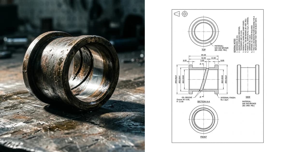
The line stopped at three in the morning. The part that failed is a bronze bushing nobody has stocked since 2004, the machine builder was bought twice and the drawing archive went with them. What you have is the broken part, a caliper and a maintenance manager asking when you will be running again. This is how you get from that object to something a machine shop will actually quote, and the three places people lose time and money on the way.
Our articles are still written by humans!
Get human written articles in your Google feed.
The problem, stated plainly
Industrial machinery outlives its documentation by decades. Packaging lines, presses, conveyors, mixers and bottling equipment routinely run thirty or forty years, which is longer than the companies that built them, longer than the CAD formats the drawings were stored in, and far longer than anyone keeps a spares inventory. So the failure mode is familiar: a part wears out, the OEM has discontinued it or quotes a fourteen week lead time, and the machine is worth more per day of downtime than the part is worth at any price.
The good news is that a competent shop can make almost any of these parts. The bottleneck is never machining capacity. It is that nobody can machine from a photograph, and the drawing does not exist.
Four options when the OEM says no
Match the route to the part, not to the technology you own
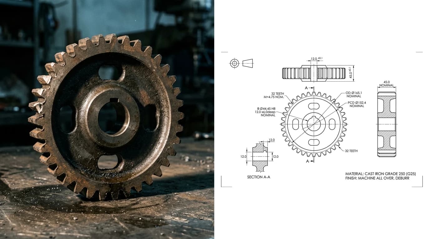
Start with the first row every time, because it is free and it is astonishing how often it works. Anything that rotates, seals or fastens is probably a catalogue item wearing a coat of grime. Wire brush it, look for a part number, measure the bore and outside diameter, and check a bearing or seal catalogue before you commission anything at all.
For everything else, the practical question is which of the remaining three you need, and the honest answer is usually a combination: draw the whole part fast, then measure the two or three features that decide whether it fits. The general method for that is in how to reverse engineer a part without the original drawing, which walks through the methods side by side. This post is about the judgement calls that guide takes for granted.
The trap: copying a worn part
Here is the mistake that costs the most and gets caught the latest. The sample in your hand is not the part as designed. It is the part after years of service, and every dimension you measure carries that history:
- Bores that carried a rotating shaft are oval, not round, and larger than nominal. Measure one in two axes and you will get two different numbers.
- Shafts and journals are undersize, often by more than the fit tolerance they were made to.
- Gear and sprocket teeth are thinned and hooked on the drive flank and untouched on the other.
- Sealing faces are grooved where the seal lip ran.
- Anything that was pressed or hammered has burrs and mushroomed edges that were never on the drawing.
Copy all of that faithfully and you manufacture a brand-new worn-out part. It might even fit, briefly, because it matches the equally worn mating components. Then you replace the mating part and nothing lines up.
Then round to design intent. A shaft measuring 24.88 mm was almost certainly 25 mm h7. A bore at 40.06 mm was 40 mm H7. Designers choose round numbers and standard fits, so a measurement sitting just under a round number is nearly always that number plus wear. If you are not sure how to read the fit that was intended, reading tolerances on a drawing covers the notation.
What a 3D scan actually gives you
Search this problem and most of what you will find is a scanning service, which is reasonable because scanning is genuinely good at some of it. It is worth being precise about which parts of the job it does.
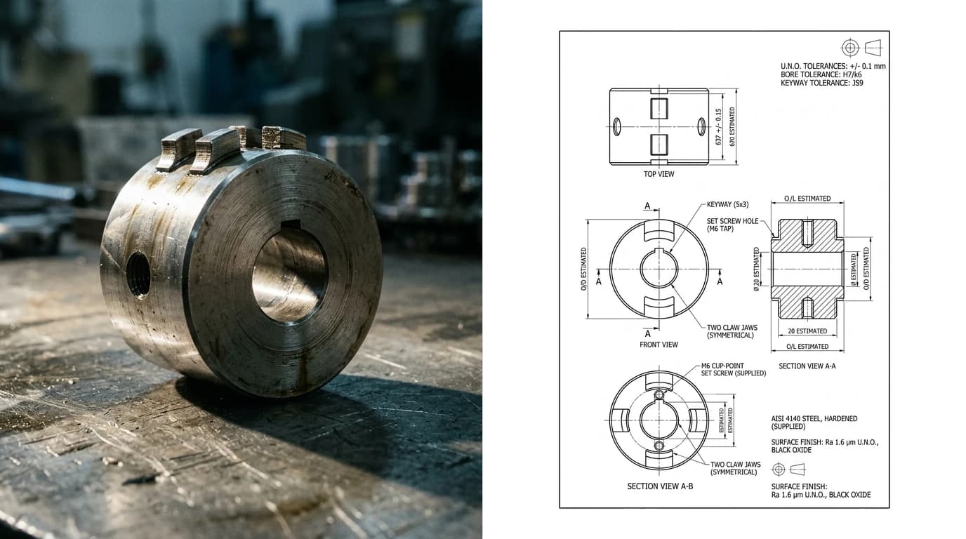
A scanner produces a point cloud: a few million coordinates on the surface of the object. That gets converted to a mesh, a shell of triangles. To become something you can manufacture from, the mesh then has to be interpreted into surfaces and features, fitted, trimmed and stitched into a solid model. That chain from cloud to mesh to trimmed surfaces to a watertight solid is a real engineering task, and it is where the days go.
Three things a scan does not give you, no matter how good it is:
- Tolerances. A scan says this surface is here. It cannot say this diameter is a press fit and that one is clearance.
- Material and treatment. Geometry is silent about whether the part is EN8 or 316 stainless, and whether it was case hardened.
- Design intent. It records the wear as diligently as the design, so it inherits the whole problem from the section above.
So scan when the geometry is freeform and you genuinely cannot measure it: impellers, cast housings, turbine blades, hobbed gear flanks, anything organic. For a bushing, a lever, a plate or a gear, hand measurement plus a drawing is faster, cheaper and more useful. The same point applies to AI mesh generation from photographs, which is a real capability but produces a textured mesh rather than a parametric CAD solid.
What a shop needs to quote
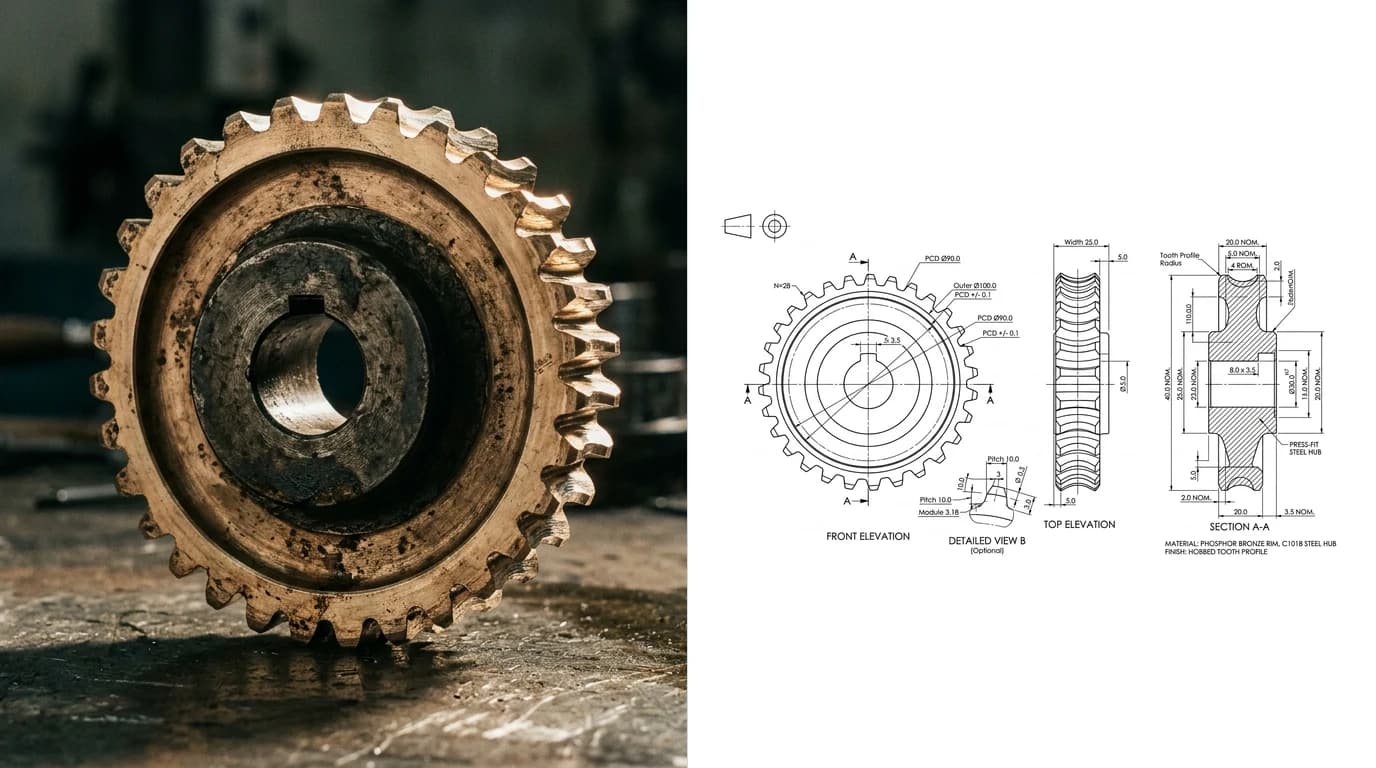
Send a shop a photograph and you will get an email back asking for a drawing. Send a STEP file alone and, more often than people expect, you will get the same email. The reason is that machine shops still want the 2D sheet: a solid model carries geometry but no tolerances, no surface finish, no material and no note about which features matter.
The minimum quotable package for a one-off replacement:
- Dimensioned orthographic views, with a section through anything internal.
- Material specification, and heat treatment or coating if any.
- Tolerances: a general tolerance note such as
ISO 2768-mfor the ordinary dimensions, and specific tolerances on the few that govern fit. - Surface finish where it matters, typically on bores and sealing faces.
- Thread callouts with size, pitch and class.
- Quantity, and whether you want one now or a spare on the shelf.
The full bar a drawing has to clear before a shop can work from it is in what makes a drawing manufacturing-ready, and CAD file formats for manufacturing covers what to send alongside the PDF.
The photo route and its ceiling
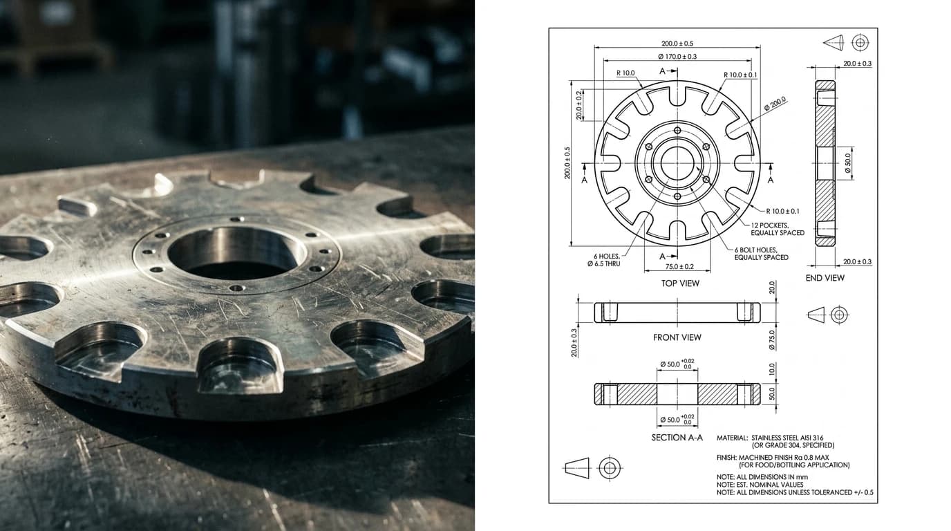
For prismatic and turned parts, going from a photograph to a dimensioned drawing is now the fastest first move, and it is worth being clear about both what that buys you and where it stops.
What it does
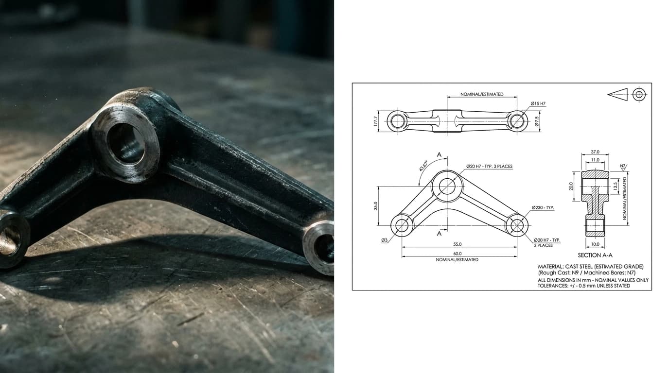
Photograph the part against a plain background, enter one dimension you measured with a caliper, and TechDraw AI reconstructs orthographic views scaled to that reference, exported as DWG, DXF, SVG or PDF. For a flat part the DXF is already the production file. For anything else you open the DWG in your own CAD and correct it. If that is AutoCAD, the AutoCAD handoff is a file you simply open. The mechanics of getting a reliable measurement out of an image are in getting dimensions from a photo, and the full walkthroughs by starting format are JPG to CAD and JPG to DWG.
Where it stops
It gives you geometry and scale. It does not give you engineering. It cannot tell you the material, it cannot see the bore behind the flange, it does not know that one of those two diameters is a bearing seat, and it will faithfully reproduce a worn profile because a worn profile is what the camera saw. Every one of those is a decision a person has to make, and they are the decisions that determine whether the part works.
Is this legal?
Worth answering properly, because the question stops more maintenance managers than it should and the general answer is more permissive than people assume.
In the United States, reverse engineering a product you legitimately obtained is generally lawful. The Supreme Court has held that state trade secret law cannot rule out discovery by fair and honest means, and reverse engineering is the standard example of such a means. Buying a machine and studying the parts inside it is not misappropriation.
The lines that do exist are worth knowing:
- Patents are different. A live patent gives its owner exclusive rights to make the claimed invention. Reverse engineering is a lawful way to learn how something works; it is not permission to manufacture something the claims cover. For a bushing or a lever this is rarely an issue. For a novel mechanism it might be, and the patent is public, so it is checkable.
- Contracts can bind you where trade secret law does not. Supply agreements, service contracts and NDAs sometimes carry explicit anti-reverse-engineering clauses, and those terms can hold even though the underlying activity would otherwise be lawful.
- Improper means are still improper.The protection covers honest analysis of something you own, not information obtained through a leak, a former employee's files, or deception.
None of this is legal advice and jurisdictions differ, so if the part is anything more interesting than a wear item, check the patent status and read your supply agreement before you commit to a production run.
Before you place the order
- Confirm it is not a catalogue part with the dirt cleaned off.
- Photograph the part from several angles before anything else, including the failure surface. You may not get a second look at it.
- Identify every surface that was in contact with something else.
- Measure the unworn areas and use them to reconstruct the worn ones.
- Round to standard sizes and standard fits where the evidence supports it.
- Verify the material, by supplier records, a hardness test or a spark test, rather than guessing from colour.
- Mark the two or three features that govern fit and tolerance them properly. Put a general tolerance note on the rest.
- Check the mating parts for wear too, or you will be back here soon.
- Order one, fit it, then order the spare once it has run. Not the other way around.
- File the drawing somewhere the next person will find it in 2040.
That last point is the one everyone skips and everyone regrets. The reason you are in this situation is that somebody twenty years ago made a part and did not keep the sheet. If you are working through a shelf of them, AI technical drawings for machine parts is the version of this aimed at machine shops.
Frequently asked questions
How do I get a drawing for an obsolete part?
You reconstruct it from the part itself. Measure the sample, recover the dimensions the part was designed to rather than the ones it has worn to, and produce a dimensioned 2D drawing with tolerances and material. Photograph-to-drawing tools get you a scaled, dimensioned starting sheet in minutes; a metrology lab or a machine shop with a CMM does it to tighter accuracy for more money and more time. Either way the deliverable a shop can quote from is a dimensioned drawing, not a photo and not a mesh.
Is it legal to reverse engineer a replacement part?
In the United States, reverse engineering a product you legitimately obtained is generally lawful, and the Supreme Court has held that state trade secret law cannot rule out discovery by fair and honest means such as reverse engineering. Patents are the different case: a valid patent gives its owner exclusive rights, and reverse engineering does not entitle you to manufacture something covered by the patent claims. Contract terms can also bind you where a purchase agreement or NDA prohibits it. This is general information rather than legal advice, so check the patent status and your contracts before you order a batch.
Can I just 3D scan the obsolete part?
A scan is a good input and a poor output. Scanners produce a point cloud, which becomes a mesh, which then has to be interpreted into surfaces and features before it is a manufacturing definition. The scan records the part's surface as it is today, including the wear, and it does not tell you which diameter is a running fit, what the material is, or which faces matter. You still need someone to decide those things and write them on a drawing.
Should I copy the worn part exactly?
No, and this is the most common expensive mistake. The sample in your hand has been running for years, so its bores are oval, its shafts are undersize and its tooth flanks are polished away. Copying it faithfully reproduces the wear and gives you a replacement that starts life at the end of its service life. The job is to recover the original intended geometry: round the measurements to sensible design values, restore nominal dimensions on worn surfaces, and use the unworn areas of the part as your reference.
What does a machine shop need to quote a one-off replacement part?
A dimensioned 2D drawing with material, tolerances, surface finish and any threads or fits called out, plus quantity. A photo is not quotable. A 3D model alone is usually not quotable either, because the model carries no tolerances and no finish, which is exactly why most shops still ask for the 2D sheet even when a solid model exists.
How accurate do the dimensions have to be?
It depends entirely on the feature. Overall envelope dimensions can be a millimetre out with no consequence. A bore that carries a bearing, a shaft that runs in a bushing, or a face that sets a gear mesh have to be right to hundredths, and those are the few features worth measuring properly with a micrometer or a bore gauge rather than inferring. A sensible workflow gets the whole part drawn quickly, then tightens the handful of dimensions that actually govern fit.
Can AI make the drawing from a photo of the part?
It can produce a dimensioned, scaled 2D drawing that is a genuinely useful starting point, provided you anchor it with a real measurement you took yourself. What it cannot do is know the material, decide which fits are critical, or see inside the part. Treat it as the draft that saves you the tracing, then apply the engineering judgement that turns a drawing of a part into a drawing you can order from.
Sources
- IPWatchdog: Reverse engineering and the law, understanding the restrictions
- Cadence: Reverse engineering of mechanical parts, resolving component obsolescence
- Point2Cyl (arXiv): reverse engineering 3D objects from point clouds, the mesh to B-Rep chain
- Tarvin Precision: reverse engineered parts, replacement components and legacy hardware
- ISO 2768: general tolerances for linear and angular dimensions