

“JPG to CAD” reads like a file conversion, the way a JPG turns into a PNG. It is not that simple. A JPG stores coloured pixels; a CAD file stores real lines, arcs and circles as math. Nothing inside a photo is a line yet, so the real job is to turn your picture into geometry and then make that geometry the right size. Do both and the CAD drawing you open in AutoCAD, Fusion or your cutter's software will match the part you had in mind. Skip them and you get a nice looking outline that machines out at the wrong scale.
Our articles are still written by humans!
Get human written articles in your Google feed.
Convert your JPG to CAD right here
Open the full converter pageDrop a file here. It never leaves your browser.
PNG, JPG, WebP, GIF, BMP, HEIC, TIFF, AVIF · any size · free · DXF or DWG · works best on clean line art, logos and high contrast shapes
The short answer
There are two honest routes from a JPG to a CAD file, and which one you need depends entirely on what the JPG shows. If the JPG is a clean drawing or a flat graphic, a logo, a scanned line drawing, a screenshot from a design tool, then a vectorizer traces the visible edges into lines and arcs and you save it as DXF or DWG. That part is close to one click. If the JPG is a photo of a real object, tracing only hands you the silhouette, at whatever size and angle the camera happened to catch. To get a CAD file you can actually build from, you rebuild it as a dimensioned drawing and anchor it to a real measurement. Either way, the pixels never become geometry on their own. Something, a tracer or you, has to draw the lines.
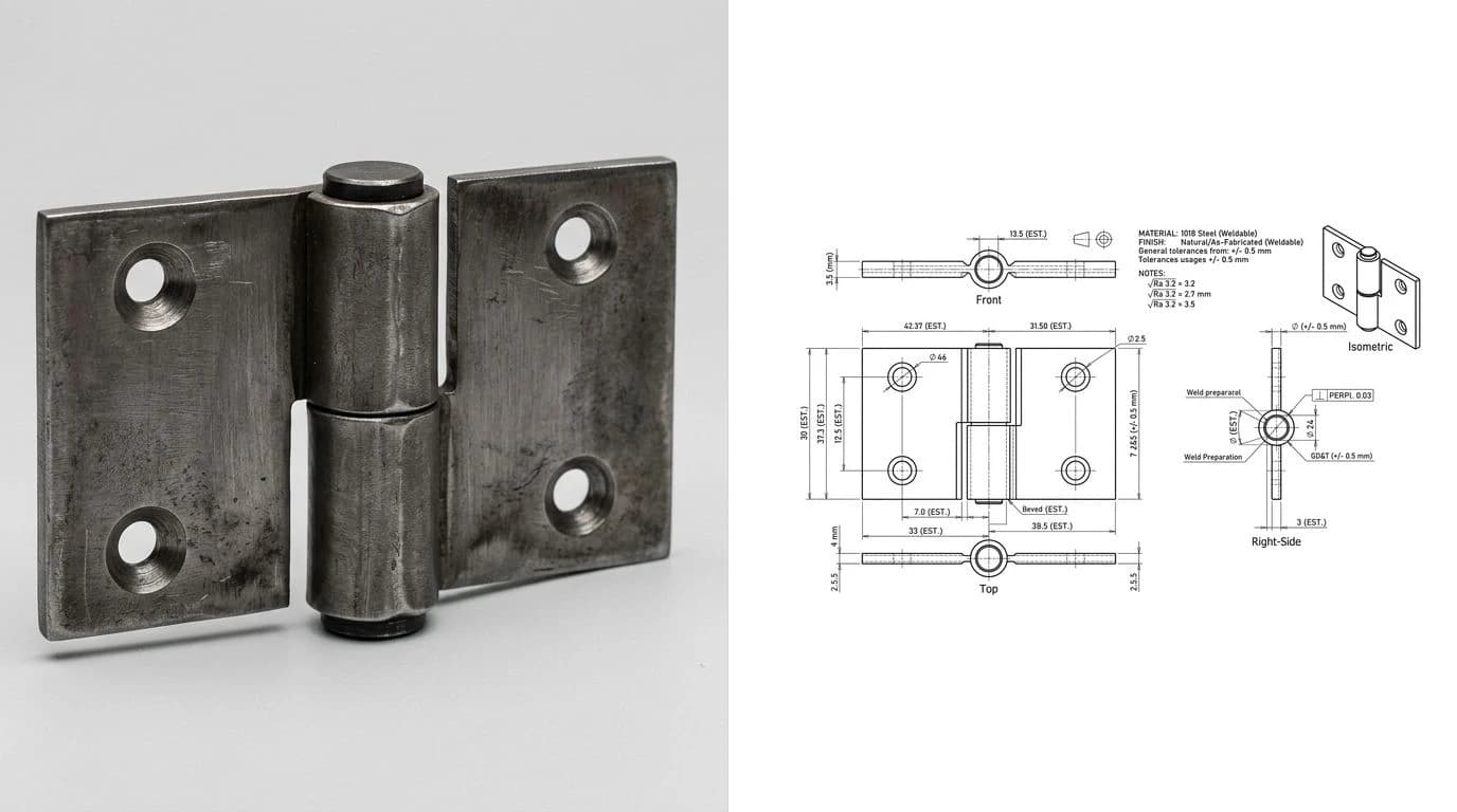
What “to CAD” actually means
People type “jpg to cad” when they want something editable out the other end, but CAD is not a single file type. It is a family. In practice, converting a JPG lands you in 2D CAD: flat geometry you can open, edit and send to a machine. That usually means a DXF or a DWG, the two formats AutoCAD and almost every cutter share. It does not, from a flat photo, mean a 3D model. If you are still weighing what “CAD” should mean for your part, the pillar guide image to CAD: turn a photo into an editable drawing walks the whole ladder from pixels to a manufacturable file. This page stays narrow: a JPG in, a 2D CAD drawing out.
Which JPG are you converting?
This is the decision that quietly determines whether the whole thing works, and most bad conversions come from skipping it. Three very different things all get saved as a “.jpg”:
Three kinds of JPG, three different jobs
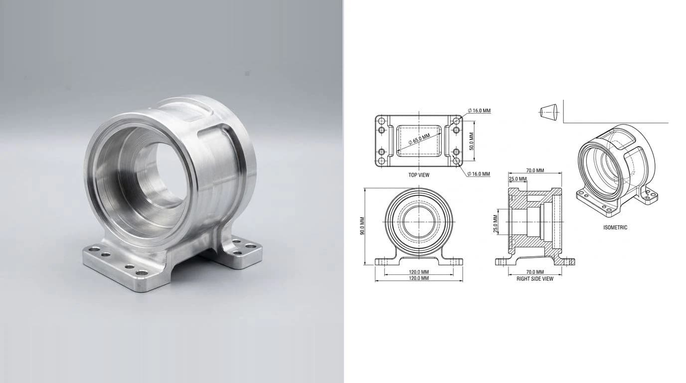
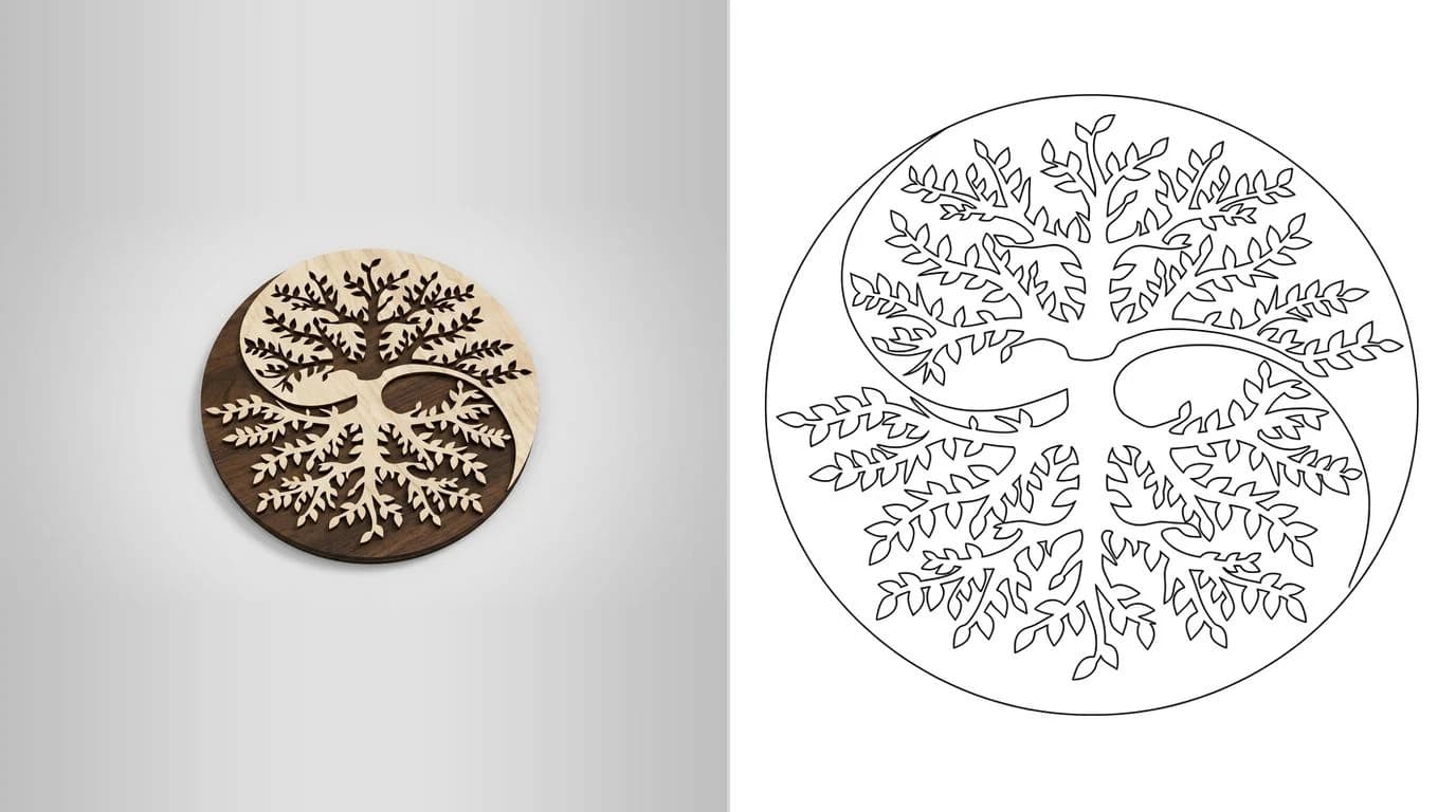
A logo or a line drawing is the friendly case, because the artwork already is the geometry. The trace is faithful and the only real work left is scale. Logo to vector for laser engraving covers that path end to end. A photo of a real part is the hard case, and it is worth being blunt about why: a camera flattens a three-dimensional object onto a grid of pixels, so any tilt or perspective bends the outline, and there is no depth, no hidden edge and no dimension anywhere in the file.
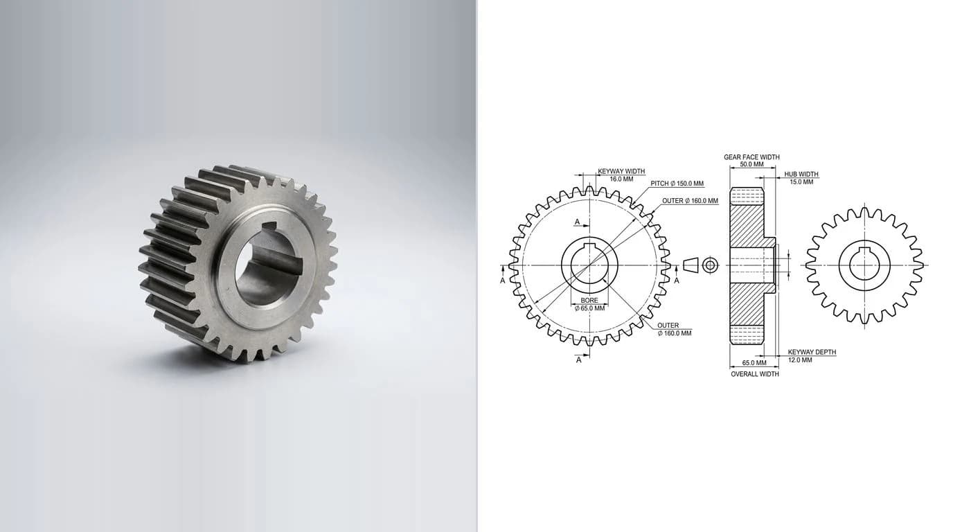
Trace it or redraw it
Tracing, also called vectorizing or raster to vector, walks the visible edges in the JPG and lays vectors along them. It is fast and, on clean input, genuinely accurate to the shape it can see. Its ceiling is just as clear: it copies what is there, and only what is there. It cannot invent an edge the camera missed, straighten a line the lens bent, or know that two nearly touching pixels were meant to be one crisp corner.
Redrawing means using the JPG as a background reference and drawing clean geometry over it, either by hand in CAD or with an AI tool that reconstructs the drawing for you. It is more work, but it is the only route to a file with real dimensions, proper corners and closed contours. The rule of thumb is short: trace when the JPG is already a drawing, redraw when the JPG is a photograph of a thing. If your trace comes out rough, with doubled lines, jagged arcs or broken corners, that is almost always an input problem, and why a traced image looks jagged and how to fix it walks through the cleanup.
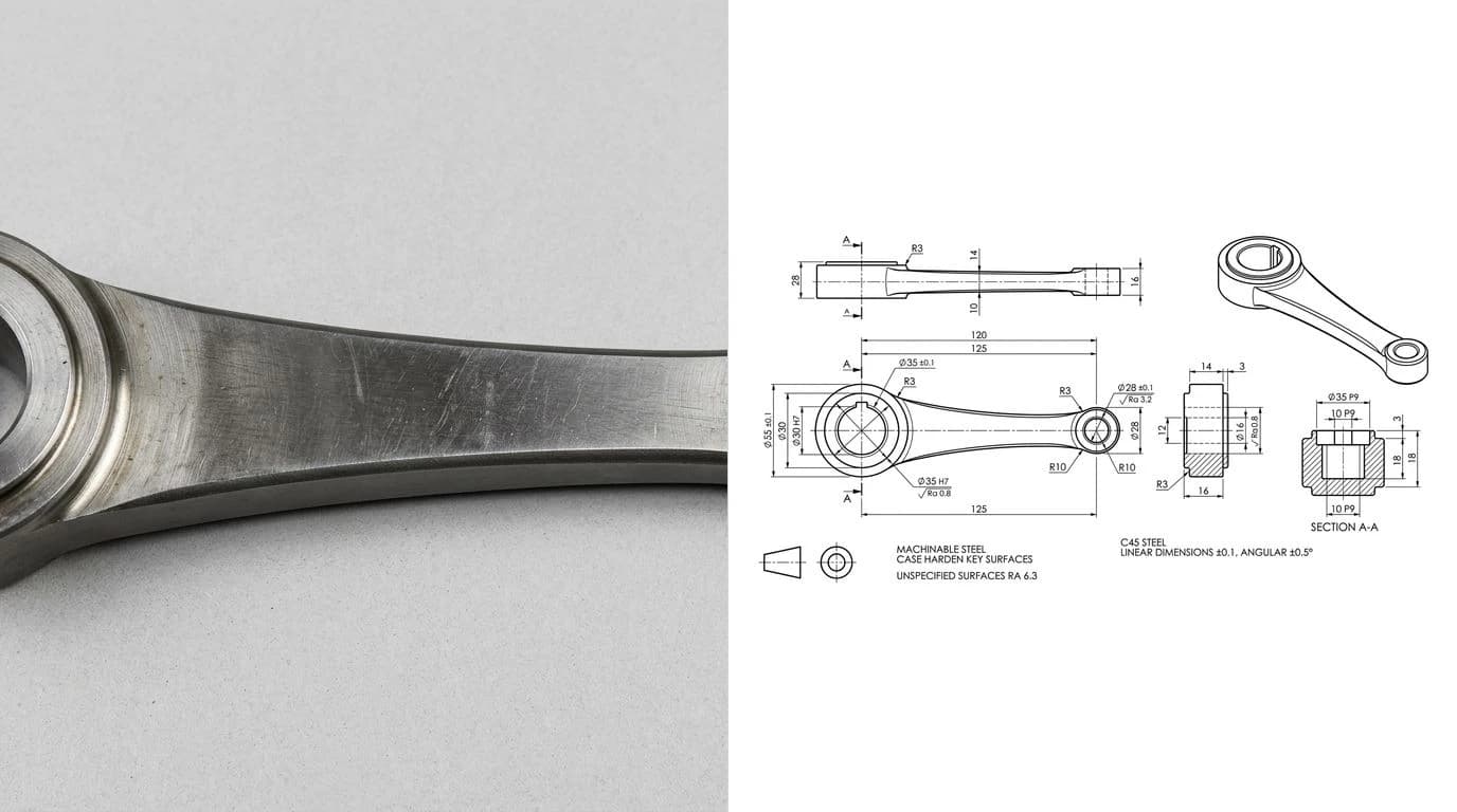
Why a JPG fights you
Of all the raster formats, JPG is the one that makes a converter's job hardest, and it helps to know why before you blame the tool. JPG uses lossy compression tuned for photographs of faces and landscapes, not crisp mechanical edges. Where a real part has a sharp black line on white, the compression paints a soft grey halo and a faint checkerboard of blocks around it. A tracer has no way to tell that fuzz from real geometry, so it follows it, and you end up with wobbly outlines, doubled edges and little specks that become stray cuts.
None of that means JPG is useless, it just means you fight it at the source. Start from the highest quality version of the JPG you have, not a copy pulled from a chat app that has been recompressed three times. If you can re-export the picture as a PNG or grab a native screenshot instead, do that, because a clean PNG traces far better than even a good JPG. The same converter has a page for whatever you actually have, whether that is a JPEG, a PNG or a photo straight off a phone. When you are stuck comparing the dedicated converters, the best JPG to DXF converters lines them up on exactly this kind of input.
Getting the size right
This is where more JPG to CAD jobs fail than anywhere else, and it is baked into the formats themselves. A JPG is measured in pixels. A CAD drawing is measured in real units, millimetres or inches. Nothing in the JPG records how many millimetres a pixel is worth, so the converter has to guess, and its guess is almost never your part's true size. The drawing opens looking perfectly correct, and then cuts out too big or too small.
The fix is always the same, and it is not optional. Find one dimension you know for certain, printed on the drawing or measured on the real part with a ruler or calipers, and scale the entire CAD file so that one feature matches the known number. Get a single length right and every other length follows, because the proportions were already correct. This exact failure, and how to catch it before it turns into scrap, is covered in fixing a DXF that imports at the wrong size, and the reference-measurement idea in depth lives in how to get dimensions from a photo.
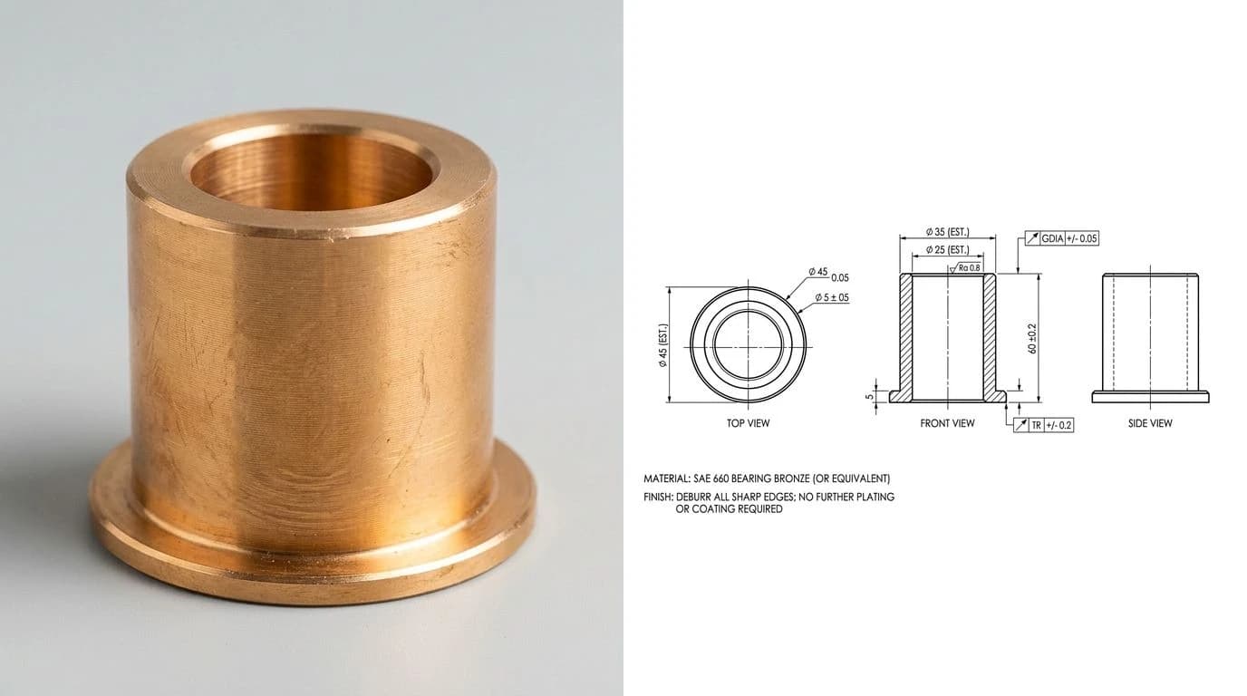
DXF, DWG or STEP?
Once you have geometry at the right size, the last question is which CAD format to save. For a JPG to CAD job the honest shortlist is short:
Where each CAD format fits after a JPG conversion
If you are choosing between the two 2D options, or a supplier asked for one specifically, DWG vs DXF lays out which to hand a shop and why. Landing specifically on DWG, because the file is going back into AutoCAD or a drafting seat, has its own end-to-end walkthrough in image to DWG: convert a picture to a DWG file, including the DWG version trap that makes converted files refuse to open. And CAD file formats for manufacturing zooms out to every format a fabricator might ask you for. The one line worth repeating: STEP is a genuinely 3D format, and you cannot reconstruct a solid from a single flat picture, no matter what a converter claims.
Tools that turn a JPG into CAD
JPG to CAD, by tool
For a logo or a clean line drawing, the free tracers are honestly enough. There is no accuracy to be bought by paying, only a little convenience. Where every one of those tools stops is the photo of a real part, because none of them can supply the one thing a picture lacks: a real-world scale, and the inner features a bare silhouette never records.
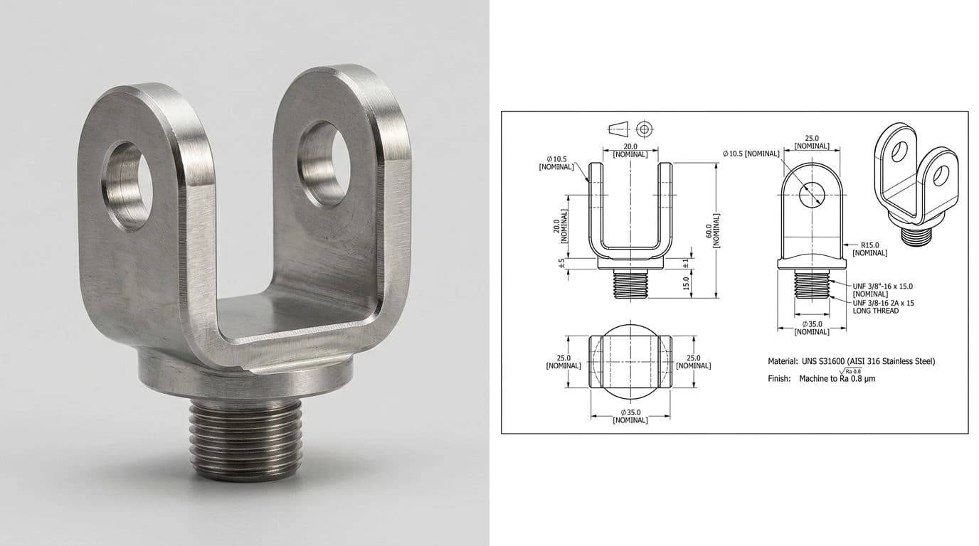
That gap is what the AI technical drawing generator is built for. You upload the JPG, type in one real measurement, and it reconstructs a dimensioned technical drawing, orthographic views, closed profiles, every length anchored to your reference instead of to pixels, then exports a clean DXF, DWG, SVG or PDF. It stays honest about the ceiling: a measurable 2D drawing you can cut or quote, not a 3D STEP solid conjured from one photo. Starting from a rough sketch rather than a photo? The sketch to CNC-ready DXF workflow covers that, and if the part is a whole existing object you are copying, reverse engineering a part from a photo goes deeper on measuring what you cannot open in CAD.
Before you cut or quote it
- Did you pick trace or redraw on purpose? A drawing gets traced; a photo of a real part gets redrawn. Guessing wrong here wastes every step after it.
- Did you start from the cleanest JPG you have? The highest quality original, not a recompressed copy, and a PNG or native export instead of a JPG whenever you can get one.
- Did you scale the drawing to one known dimension? Not assumed, verified against a print or a measured feature. This is the single most common way a JPG to CAD job becomes scrap.
- Is every cut profile closed, with no duplicate or stray lines the tracer left behind?
- Did you export the format the receiver can open? DXF for a cutter, DWG for an AutoCAD user, and never STEP from a flat photo.
Clear that list and the file is ready for the machine or the quote. If it is headed to a shop rather than your own laser, the wider question of what a fabricator needs beyond the outline is answered in from a photo to a manufacturing-ready drawing, and PDF to DXF covers the case where your picture arrived wrapped inside a PDF instead of a JPG.
Watch: A scanned drawing traced into a DWG
SourceCAD's tutorial is the trace route from this page, applied to the easy case: an image or scanned PDF that is already a drawing. Its description says it converts the scan into an AutoCAD DWG with the lines and other geometry intact, and it uses Inkscape, the free tracer in the tools table above. It is worth watching for the tracing step itself. It does not cover a photo of a real part, which still needs a redraw and a reference measurement.
Frequently asked questions
Can I convert a JPG to CAD for free?
Yes, if all you need is the outline. Inkscape traces a JPG into vectors and exports DXF for free, and free online converters handle a one-off file. What free tracing gives you is an accurate shape of what the pixels show. What it cannot give you is the real-world size or any dimensions, because a photo never contained those numbers. You add the scale afterwards from a measurement you know.
How do I convert a JPG to a DWG or DXF?
If the JPG is a clean drawing or logo, run it through a vectorizer such as Inkscape or Illustrator, then save as DXF or DWG. If the JPG is a photo of a real part, tracing only gives you a silhouette, so you rebuild it as a dimensioned drawing over the photo and export that. Either way, decide first whether the picture is a drawing or a photograph, because that decision changes everything after it.
Can you convert a photo (JPG) of a real part to a CAD file?
You can, but it is a different job from tracing artwork. A flat, straight-on JPG of a part traces into a faithful outline, but a bare outline has no dimensions and any camera tilt distorts the shape. For a part you actually intend to make, generate a dimensioned drawing from the photo using one reference measurement, then export that to DXF or DWG rather than trusting a raw trace.
Why is my CAD file the wrong size after converting a JPG?
Because a JPG has no units. It is a grid of pixels, so any converter can only output the shape, not how big it is in millimetres or inches. The CAD file lands at whatever scale the tool guessed. Fix it by setting one known dimension on the result, or by measuring a feature on the real part and rescaling the whole drawing to match, before you send it anywhere.
Is JPG or PNG better for converting to CAD?
PNG, whenever you get the choice. JPG compression adds soft halos and blocky artifacts around every edge, and a tracer follows those artifacts as if they were real geometry, so you inherit fake bumps and doubled lines. A crisp PNG, or a high-resolution screenshot exported straight from a design tool, gives the converter clean edges and a noticeably cleaner result.
What CAD format should I export, DXF or DWG?
For 2D work headed to a laser, plasma or CNC cutter, DXF is the safe neutral choice almost every machine reads. DWG is AutoCAD's native format and makes sense when the person receiving it works in AutoCAD. If someone asks for a 3D STEP solid, be honest that a single JPG cannot become one, because a flat photo has no depth to reconstruct.
Is JPEG the same as JPG for CAD conversion?
Yes, identical. JPG and JPEG are the same format; the three-letter version only exists because old Windows systems limited extensions to three characters. Every converter, tracer and CAD import treats them the same, so nothing changes about the workflow. What matters is the compression quality inside the file, not which spelling the extension uses.
What is the best JPG to CAD converter?
It depends on the input. For logos and clean line art, Inkscape's free Trace Bitmap is genuinely hard to beat, and Scan2CAD earns its price on batches of scanned drawings. Free online converters are fine for a quick one-off outline. For a JPG photo of a real part, none of the tracers deliver a usable file, and an AI rebuild tool that outputs a dimensioned drawing is the only route that adds the missing sizes.