A machine goes down. The part that failed is a plain metal bracket, no markings, and the company that made the equipment stopped supporting it years ago. There is no drawing, no model, no part number that leads anywhere. A shop can make a new one in an afternoon, but only if someone hands them a drawing first. That gap, a part in your hand and no paperwork to reproduce it, is what reverse engineering closes.
The problem: a part and no paperwork
Reverse engineering sounds like espionage, but in a workshop it is mundane and constant. A gear strips, a mounting plate cracks, a discontinued spacer is the only thing standing between a line and production. The part exists, it works, and nobody can find a drawing for it. You cannot quote, cut or machine a replacement from the part alone. The shop needs a dimensioned drawing, and somebody has to create one from the object itself.
What reverse engineering actually means
Stripped to its core, reverse engineering a part is two steps: capture the geometry of the physical object, then express it as a manufacturable drawing or model, with real dimensions, tolerances and material notes. The output is the same thing a designer would have produced in the first place: a drawing a shop can build from, ideally exported to DXF or DWG for CNC and laser, or a 3D model for printing and machining. For what makes that output truly buildable, see our manufacturing-ready checklist.
The three methods, compared
There is no single right way, only the one that fits the part, your budget and how fast you need it. Here is the honest trade-off.
Ways to reverse engineer a part (2026)
| Method | Best for | Speed | Cost | Catch |
|---|---|---|---|---|
| Calipers + CAD | Simple prismatic parts | Hours | Low (skill + time) | Tedious, error-prone by hand |
| 3D scanning | Organic, freeform shapes | Hours to days | High (hardware + cleanup) | Overkill for flat parts |
| Photo + AI | Brackets, plates, machined parts | Minutes | Low (freemium) | Needs one reference measurement |
For a curvy turbine blade, a scanner earns its price. But the daily reality of most shops is not turbine blades. It is brackets, plates, flanges, spacers and covers, parts built from flat faces, holes and simple radii. For those, measuring by hand works but burns an afternoon, and that is exactly where the photo-and-AI route changes the math.
The fast way: a photo and AI
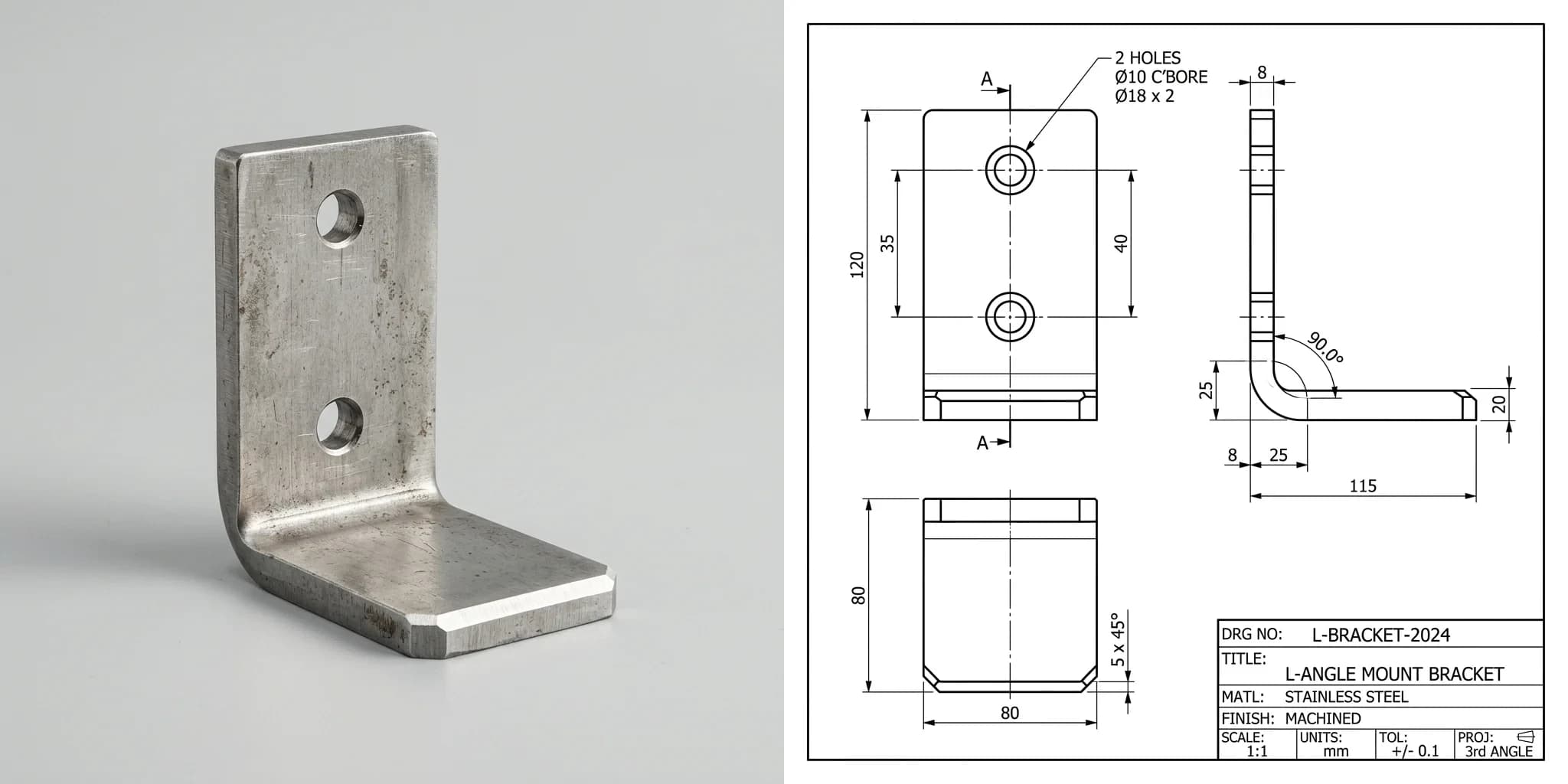
This is the part people do not believe until they see it. You photograph the part, tell the tool one real measurement so it knows the scale, and it generates a clean, dimensioned technical drawing of the object, orthographic views, dimensions, title block and all. Here is a real example: a stainless L-bracket with two counterbored holes, and the drawing TechDraw AI produced from a single photo of it.
 Photo
Photo Drawing
That drawing is not a render that merely looks technical. It carries the outline, the hole positions and the callouts a shop needs to quote and cut. The same approach handles the everyday catalogue of shop parts: flanges, spacers, hinges and plates. We pulled apart what AI can and cannot do here in from photo to manufacturing drawing, and the broader image-to-CAD picture in turning an image into CAD. If the part in question is a worn spare off a machine that is currently stopped, obsolete machine parts covers the judgement calls that case adds: recovering design intent from a worn sample, what a 3D scan will and will not give you, and where the patent line sits.
Doing it in TechDraw AI, step by step
The whole point is that this is not a research demo, it is a workflow you can run right now. Three steps, start to export.
1. Upload a photo of the part
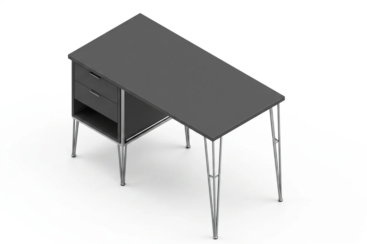
Shoot the part straight on, in even light, with the main face square to the camera. The cleaner the photo, the cleaner the geometry the tool extracts.
2. Set one real measurement
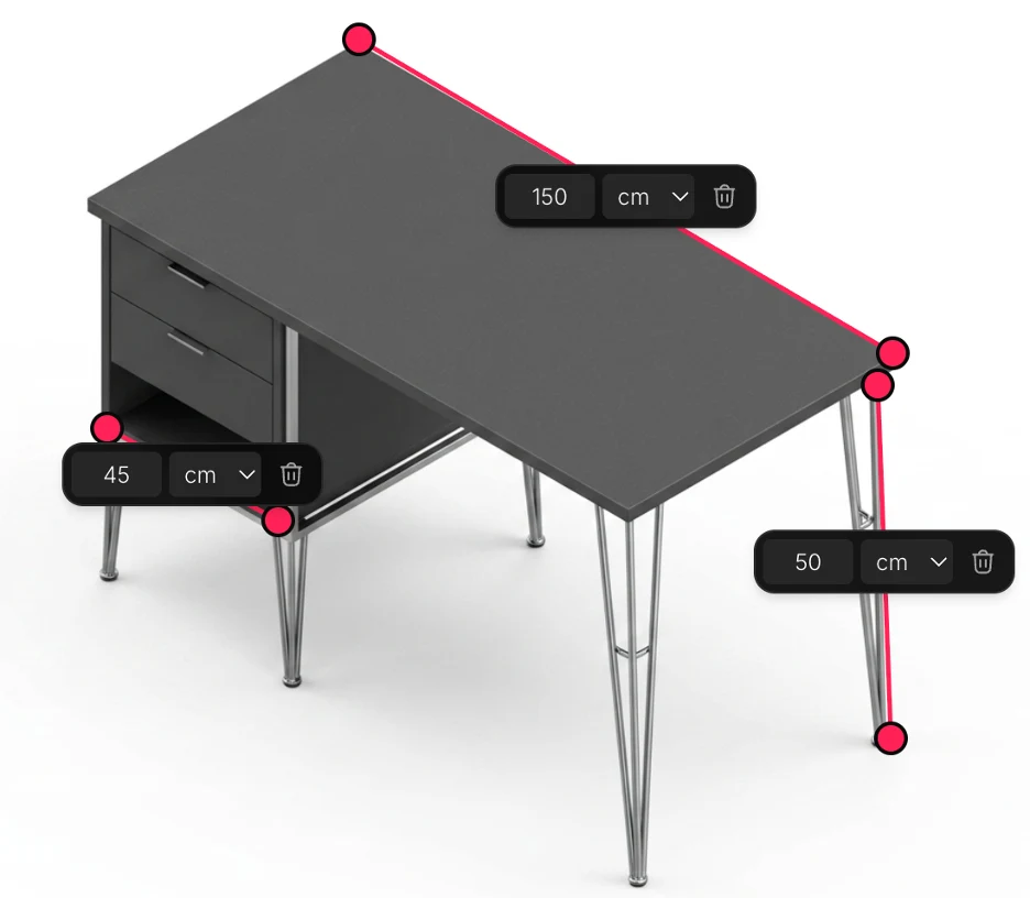
This single step is what separates a real drawing from a guess. Measure one feature, an overall length or a hole spacing, and enter it. The tool scales the entire drawing from that reference, which is why the numbers come out true rather than invented.
3. Generate and export the drawing
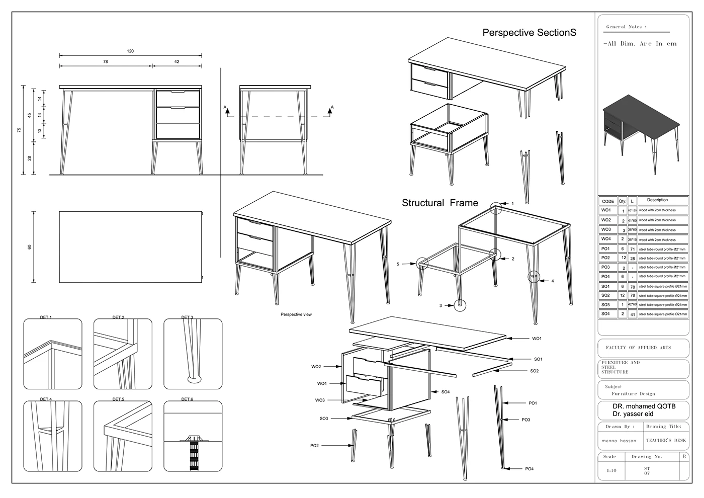
The tool lays out the views, places the dimensions and fills the title block, then exports the file your shop or your laser cutter actually wants. From there it is a normal CAD file: our CAD workflow guides walk you through importing the DXF into Fusion 360, SolidWorks or FreeCAD to rebuild it as a parametric model, or you can send it straight out. You can try it free on your own part.
The one thing to get right: scale
One bit of physics decides whether any photo-based method is being honest with you. A single photograph cannot reveal a part's absolute size. A small part close to the lens and a large one far away can fill the frame identically, so shape is recoverable and size is not, unless something of known size is in the picture. That is a property of cameras, not a limitation better software will fix.
- A tool that returns confident dimensions from one photo with no reference and no questions is making the numbers up.
- A tool that asks for one known measurement can anchor every other dimension and produce a drawing that is genuinely to scale. More on this in are AI technical drawings accurate.
Before you cut metal
AI gives you a fast, accurate first draft. A person still signs off. Run this quick check before a reverse-engineered part goes to a shop:
- Confirm the critical dimensions with calipers, especially anything that mates, threads or locates another part.
- Add tolerances where fit matters. A bare number is not enough for a bearing seat or a dowel hole. See our guide to dimensioning.
- Name the material and finish. The original may be a specific alloy or have a hardened surface that matters to function.
- Mind bent sheet metal. If the part is folded sheet, the unfolded flat pattern is its own task; see sheet metal drawings from a photo.
- Check the file. Export the right format and version for the machine, the trap we cover in DWG vs DXF.
- Reverse-engineering furniture instead of metal? The same idea applies, but joinery, grain and wood movement replace tolerances and alloy; see furniture shop drawings from a photo.
Do that, and you have closed the loop: a broken part with no paperwork becomes a clean, manufacturable drawing, in minutes rather than an afternoon. That is reverse engineering in 2026, and it is the exact job TechDraw AI was built to do.
Frequently asked questions
How do you reverse engineer a part?
You capture the part's geometry, then turn it into a drawing or CAD model you can manufacture from. The classic route is measuring every feature with calipers and rebuilding it in CAD. Faster routes are 3D scanning, or photographing the part and letting AI generate a dimensioned drawing anchored to one known measurement. Whichever you use, a person confirms the critical dimensions before anything is cut.
Can you make a technical drawing from a physical part?
Yes. That is exactly what reverse engineering produces. With calipers and CAD it takes hours; with a tool like TechDraw AI you photograph the part, confirm one reference dimension so the drawing is to scale, and export a dimensioned drawing as DXF, DWG, SVG or PDF in minutes.
Is it legal to reverse engineer a part?
Reverse engineering a part you own for repair or replacement is generally fine. Copying a part that is protected by an active patent, or a design or copyright, to sell can infringe those rights. When in doubt about a commercial product, check the part's IP status before reproducing it at volume.
Do I need a 3D scanner to reverse engineer a part?
No. A 3D scanner helps for complex organic shapes, but most brackets, plates, gaskets, spacers and machined parts are made of simple features you can measure with calipers or capture from a clear photo. For prismatic parts, a photo plus one reference measurement is often enough to produce a manufacturable 2D drawing.
How accurate is reverse engineering from a photo?
Shape comes out reliably; absolute size depends entirely on giving the tool one real measurement to anchor to. A single photo with no reference cannot recover true scale, so any tool that returns confident dimensions from one image with no questions is guessing. Anchored to one caliper reading and confirmed by a human, the result is accurate enough to manufacture.
Want the short version? See our quick answer: How do I reverse engineer a part when there are no drawings?