Anyone can put numbers on a drawing. The skill is choosing which numbers, measured from where, and how tight. Get it right and a shop quotes and builds your part without a single question. Get it wrong and you get an email full of them, or worse, a box of parts that match the drawing and still do not work. Here are the rules that decide which one you get.
Rule 1: Dimension for function, not for how you drew it
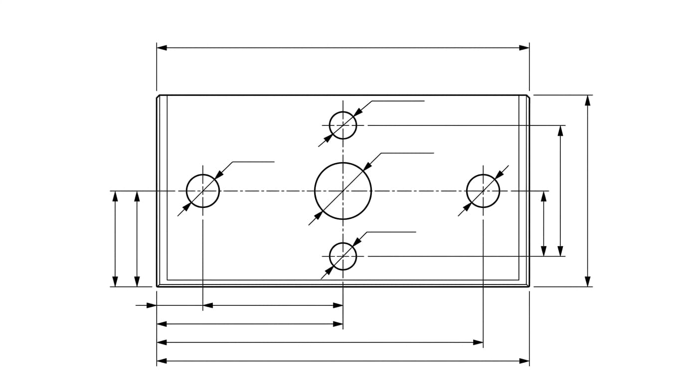
This is the rule the other seven serve. A dimension is a message about intent. When you measure a hole from the machined edge that locates the part in its housing, you are telling the machinist what matters. When you measure it from whatever corner your cursor happened to be near, you are telling them nothing, and they will guess.
Before you place a single dimension, ask how the part is used. Which faces touch other parts? Which features have to line up with something else? Those mating surfaces are where your dimensions should originate. Functional dimensioning is the principle that you define a part from the features relevant to its function, assembly and performance, using the minimum set of dimensions that pins the geometry down without ambiguity.
Rule 2: Dimension each feature exactly once
Every feature needs enough dimensions to define it and not one more. Give a hole its diameter, not its diameter and its radius. Give a slot its length once, not from the left and again from the right and again overall. This is the difference between a clean drawing and an over-dimensioned one.
Over-dimensioning is not just untidy. The moment a feature carries two dimensions that should agree, they eventually will not, because of a typo, an edit or a rounding choice. Now the shop has two numbers and no way to know which is right. The opposite mistake, leaving a feature under-dimensioned, forces the shop to scale the print or invent a value. Aim for exactly enough.
Rule 3: Know when to use baseline and when to use chain
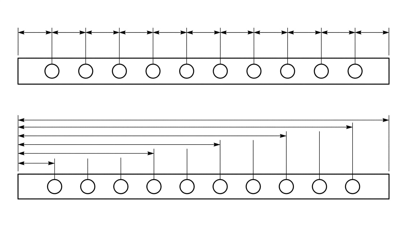
There are two ways to lay out a row of dimensions, and the choice has real consequences.
- Chain dimensioning measures each feature from the one before it. It reads naturally, but the tolerances add up. If four features in a chain each allow plus or minus 0.1, the distance from the first to the last can drift by 0.4. That accumulation is called tolerance stack-up, and it is a classic cause of parts that will not assemble.
- Baseline dimensioning measures every feature from one common reference. Each feature carries its own tolerance against the baseline, so errors do not accumulate down the row.
The rule of thumb: if the distance from a single edge or datum is what matters, use baseline. If the gap between neighbouring features is what matters for interchangeability, use chain, and budget for the stack-up. Most precise parts lean on baseline for exactly this reason. How those datums and tolerances are actually notated on the sheet, in feature control frames and the rest, is covered in our guide to engineering drawing symbols and GD&T.
Rule 4: Choose datums that match reality
A datum is the reference a dimension is measured from, a surface, an edge, an axis or a centre plane. Good datums are not arbitrary. They should be the same features that locate the part when it is assembled and the same features an inspector will rest it against when they measure it.
When your drawing datum, your assembly locator and your inspection reference are all the same surface, everyone is measuring the part the same way you designed it. When they differ, you have invited a quiet disagreement between design, manufacturing and inspection that only surfaces when parts are rejected.
Rule 5: Do not over-tolerance
Tolerance is where dimensioning meets cost directly. A tight tolerance is not a free safety margin. It means slower feeds, extra setups, better tooling and more inspection, and you pay for all of it on every part. Tolerancing a non-critical bracket hole to a few microns buys nothing but a higher invoice.
The discipline is to separate the few features that control fit and function from the many that just need to be roughly right. Tolerance the critical ones deliberately, and let the rest inherit the general tolerance from the title block, typically an ISO 2768 class. That single decision often has more effect on part cost than the geometry itself.
Rule 6: Make the layout readable
A correct drawing that is hard to read still causes mistakes. A few layout habits carry most of the benefit:
- Place dimensions outside the views and off the part wherever you can, so they do not sit on top of the geometry.
- Put smaller dimensions closer to the view and larger ones further out, so extension lines do not cross each other.
- Dimension to visible edges, not to hidden (dashed) lines.
- Put each dimension on the view where that feature reads most clearly, and group related dimensions so the eye is not ricocheting around the sheet.
- Keep a consistent gap between the part and the first dimension line, and between stacked dimension lines.
Rule 7: Leave nothing to be calculated or measured
The shop should never need a calculator or a ruler on your print. If a hole's position can only be found by adding up a chain of other dimensions, you have made the reader do arithmetic, and arithmetic carried out under time pressure is where errors live. Give every feature a clear size and a clear location directly.
The same goes for the obvious-looking gaps. If a wall thickness, a clearance, or an angle matters, state it. Relying on the reader to derive it from the geometry is relying on them to make the same assumptions you did, which is exactly what a drawing exists to prevent.
Rule 8: Run the final pass
Before a drawing leaves your hands, walk it once more with fresh eyes:
- Is every feature located and sized, and none of them twice?
- Do the dimensions originate from functional surfaces and real datums?
- Have you used baseline where stack-up would otherwise bite?
- Are tolerances tight only where function demands, and general everywhere else?
- Can someone build the part without scaling the print or doing mental maths?
Dimensioning is the part of drafting that looks mechanical and is actually judgement. The rules above are how experienced drafters encode intent so a stranger in a workshop builds exactly what was in their head. If you are not sure your finished sheet clears the bar, run it against our manufacturing-ready checklist before you send it.
Frequently asked questions
What is the most important rule of dimensioning?
Dimension for function. Place dimensions from the surfaces and features that actually matter for how the part fits, assembles and works, not from whatever was convenient while you were drawing. A machinist should be able to read your intent from the dimensions alone, without guessing.
What is the difference between chain and baseline dimensioning?
Chain dimensioning measures each feature from the previous one, so tolerances add up along the chain and the last feature can drift a long way. Baseline dimensioning measures every feature from one common reference, which stops tolerances from stacking. Use baseline when the distance from one edge matters, and chain when the gap between neighbouring features matters most.
What is over-dimensioning?
Over-dimensioning is giving more dimensions than the geometry needs, for example dimensioning both the diameter and the radius of a hole, or fixing the same length from two directions. It clutters the drawing and, worse, it can contradict itself, which leaves the shop deciding which number to trust. Every feature should be dimensioned exactly once.
How tight should my tolerances be?
As loose as the function allows. Tight tolerances raise cost through slower machining, more setups and more inspection, often with no benefit. Identify the few features that control fit and function, tolerance those properly, and let everything else fall back to the general tolerance in the title block.
Where should dimensions be placed on a drawing?
Outside the view wherever possible, off the part itself, with the smaller dimensions closer to the view and larger ones further out so extension lines do not cross. Place a dimension on the view where the feature is clearest, and group related dimensions together so the reader's eye does not jump around.