
Grok is the loudest of the big chatbots, and its image generator will cheerfully paint you a “blueprint” that no machine shop could ever use. Ignore that party trick. Underneath it sits a genuinely strong reasoning model with vision, and one ability the other chatbots do not have in the same way: live, cited search. Grok can check the current revision of a standard, hunt down a matching catalogue part or confirm what bar stock actually comes in while it plans your drawing. Here are 18 prompts that use Grok for what it is actually good at, grouped by the job, each ready to copy, paste and fill in.
Our articles are still written by humans!
Get human written articles in your Google feed.
How to prompt Grok well
A prompt is only as good as what you feed it. Four habits make every prompt below work better, and the first two are where Grok differs from the other chatbots:
- Switch on Think mode for anything with numbers. Tolerance maths, stack-ups and standards logic get visibly better when Grok reasons step by step instead of answering in one shot.
- Use DeepSearch when the answer lives in the world. Current standard revisions, catalogue parts and supplier stock are live questions, so ask for sources and click them. An uncited claim from any chatbot is a guess.
- Give it a role and a standard.“Act as a mechanical drafter working to ASME Y14.5” sets the register and the conventions before it answers.
- Attach the image and verify the output. Upload the drawing or photo instead of describing it, and treat every dimension Grok reads or writes as a first draft to check.
If you live in a different chatbot, there are parallel prompt libraries for ChatGPT, Gemini and Claude.
Read & review a drawing you upload
Grok's vision reads drawings and part photos well, and these five prompts all start by uploading something. Keep our guide on how to read a technical drawing open alongside as the human reference.
 Photo
Photo Drawing
1. Walk me through a drawing I uploaded
Turns a dense sheet into a plain-English explanation.
I've uploaded a technical drawing. Act as a mechanical drafter and walk me through it: identify each view and how they relate, list the main dimensions and what feature each one controls, explain every symbol and note, and summarise what the part is and how it would be made. Flag anything that looks ambiguous or contradictory.
2. Review an uploaded drawing the way a shop would
Surfaces the questions a machine shop would email back.
Review this drawing the way a machine shop would before quoting it. List everything that would stop them making the part: missing or unreadable dimensions, untoleranced critical features, no material or finish, no projection symbol, ambiguous notes. Return each gap as a specific question the shop would have to ask.
3. Decode every symbol and abbreviation on the sheet
Clears up the shorthand on someone else's drawing.
From the uploaded drawing, extract every symbol, abbreviation and callout you can see (for example Ø, R, THRU, CBORE, TYP, the GD&T frames and the surface-finish marks). For each one give the symbol, its meaning, and what it tells the machinist. Note any that differ between ISO and ASME conventions.
4. Pull a structured dimension and hole table off the sheet
Turns callouts into a table you can check line by line.
Read all the dimensions and hole callouts off this drawing and return them as a table with columns Feature, Nominal, Tolerance, Notes. List holes separately with diameter, depth (or THRU) and quantity. At the end, flag any value you are not fully sure you read correctly so I can verify it against the original.
5. Compare two revisions and list what changed
Catches the one dimension that quietly moved between revs.
I've uploaded two revisions of the same drawing, [REV A] and [REV B]. Compare them and list every difference you can see: changed dimensions or tolerances, added or removed features, edited notes, and any change to material, finish or title block. Present it as a change log and note anything that would affect fit or function.
Plan the drawing & write the spec
Before any geometry exists, Grok can help you decide what the drawing needs to say, the same order we follow in how to make a technical drawing. Describe the part or upload a photo and let it plan the sheet.
 Photo
Photo Drawing
6. Choose the right views
Stops you over- or under-drawing a part.
Act as a mechanical drafter working to ASME Y14.5. I need to draw this part: [DESCRIBE PART, or say "see the uploaded photo"]. List the minimum set of orthographic views that fully defines it, tell me which face should be the front view and why, and say whether I need any section or detail views.
7. Plan the dimensioning and datum scheme
A datum strategy before you place a single dimension.
For this part [DESCRIBE / LIST FEATURES / or reference the uploaded image], propose a dimensioning scheme: which faces or edges to use as datums and why, whether each feature group should be baseline or chain dimensioned, and the order to dimension features so everything is defined exactly once and nothing is over-dimensioned.
8. Turn a description or photo into a drawing spec
Converts loose intent into a structured starting point.
Convert this part (uploaded photo, or the description below) into a structured drawing specification with sections for Views, Key dimensions, Tolerances, Material, Surface finish and General notes. Before you write it, ask me up to 5 clarifying questions if anything critical is missing. Description: [PASTE, or "use the image"].
9. Draft the general notes and title block
The boilerplate text you drop straight onto the sheet.
Write a concise, shop-ready general-notes block and the title-block fields for a machined [MATERIAL, e.g. 6061-T6 aluminium] part called [NAME], part number [NUMBER], scale [1:2], units [mm], projection [third-angle], finish [FINISH], revision [A]. Cover default general tolerance, break-all-sharp-edges, deburring, coating and inspection. Use numbered notes like a real production drawing.
Check whatever it drafts against our manufacturing-ready checklist before the sheet goes out.
Standards, GD&T & stack-ups
Symbols, standards and tolerance maths are language and logic, which a reasoning model handles well, especially with Think mode on. Keep our engineering drawing symbols and GD&T guide open as the human-written reference.
 Photo
Photo Drawing
10. Explain or write a GD&T callout
Decodes a feature control frame, or picks the right one.
Two things. First, explain this GD&T feature control frame in plain English: [e.g. position 0.2 (M) | A | B(M) | C], covering the characteristic, the tolerance zone, the material-condition modifiers and the datum order. Second, I need to control that [REQUIREMENT, e.g. a bore stays perpendicular to the mounting face within 0.1 mm]: tell me which characteristic to use, what datums I need, and write the exact frame to put on the drawing.
11. Recommend a tolerance strategy
Separates the features that need precision from the rest.
Recommend a tolerancing strategy for this machined part [DESCRIBE or reference the image]. Suggest a sensible ISO 2768 general-tolerance class for the bulk of the dimensions, then list which specific features (mating diameters, hole positions, sealing faces) should get tighter individual tolerances, with a suggested value and the reason. Flag where GD&T would serve better than plus/minus.
12. Work a tolerance stack-up in Think mode
Reasoning with visible arithmetic you can audit.
Think step by step. Do a tolerance stack-up for this assembly: [LIST the chain of dimensions and tolerances from one interface to the other, e.g. housing bore depth 20.0 +0.1/0, spacer 5.0 ±0.05, bearing width 7.0 ±0.12]. Show the arithmetic at each step. Give me the worst-case result and the RSS (statistical) result, state whether the required clearance of [VALUE] always holds, and tell me which single tolerance to tighten first if it does not.
Live research with DeepSearch
This group is Grok's home advantage and the part the other prompt libraries cannot copy: questions whose answers live in the current, real world. Run these with DeepSearch on and treat the citations as part of the deliverable.
 Photo
Photo Drawing
13. Verify the standard before you quote it
Standards get revised; your drawing notes should keep up.
Use live search with sources. I'm about to put [STANDARD, e.g. ISO 2768-2] in the general notes of a new drawing. Confirm whether that standard is still current, whether it has been withdrawn, revised or superseded, what the replacement is if so, and what the practical difference means for a general-tolerance note on a machined part. Give me the exact note text you would write today, and cite every source.
14. Match a measured part to a catalogue standard part
Stops you drawing something you could buy.
Use live search with sources. I measured this part: [e.g. a forged lifting eye bolt, eye outside diameter 35 mm, shank M12 x 60, shoulder under the eye]. Find which standard catalogue parts match (DIN, ISO or ASME designations), link the datasheets, list the standard's nominal dimensions next to my measurements, and tell me whether the differences are within normal manufacturing variation or whether this is a custom part I actually need to draw.
15. Check real stock sizes before you dimension
Dimensions that match stock save money at the quote stage.
Use live search with sources. I'm designing [PART, e.g. a spacer turned from aluminium round bar / a bracket cut from mild-steel sheet]. Before I finalise dimensions, list the standard stock sizes actually sold for [MATERIAL AND FORM, e.g. 6061 round bar / S235 sheet] in [REGION], with links. Then suggest how to adjust my nominal dimensions [LIST DIMS] so the part comes out of standard stock with minimal machining or waste.
Geometry as code & AutoLISP
This is the closest Grok gets to actually drawing. Its image generator cannot make CAD geometry, but code can: DXF is a text format Grok can write directly, and AutoLISP lets it automate real drafting inside AutoCAD. Reliable for simple shapes only, and it cannot judge scale or fit, so always import and check.
This walkthrough shows the AutoLISP route end to end: Grok writing a routine that AutoCAD then runs, which is exactly what prompt 17 asks for.
 Photo
Photo Drawing
16. Generate a minimal DXF or SVG to import
A starting cut file you refine in CAD or our converter.
Generate a minimal ASCII DXF (AutoCAD R12) for this geometry: [e.g. a 40 x 22 mm stepped plate with an M10 tapped hole centred, tap drill Ø8.5]. Use only LINE, CIRCLE and LWPOLYLINE entities, set units to millimetres, keep all profiles closed, and output only the DXF text so I can save it as a .dxf file. Then give me the same shape as clean, minimal SVG in millimetre units.
17. Write an AutoLISP routine that draws the part
Automation inside AutoCAD, written for you.
Write an AutoLISP routine for AutoCAD that draws this part as 2D geometry: [DESCRIBE with real dimensions, e.g. a T-slot nut profile, 40 mm wide base, 22 mm top width, 16 mm total height, M10 hole centred]. Requirements: millimetre units, closed polylines, geometry on layer PART and centrelines on layer CL, a defun I can load with APPLOAD and run as a command, and a comment on every dimension so I can edit it. Then explain in two sentences how to load and run it.
The photo hand-off
The last prompt draws the honest line between what Grok can plan and what it can actually deliver. The long version of working from a physical part is our guide to reverse engineering a part, and the scale problem specifically is covered in getting dimensions from a photo.
18. Plan the photo-to-drawing workflow
Maps the whole route when all you have is a snapshot.
I have only a photo of a part and need a manufacturing drawing and a DXF from it. Lay out the exact step-by-step workflow to get there: how to establish real scale from the photo, what to measure, which steps a person or a dedicated tool must do versus what you can help with, and how to verify the result before I send it to a shop. Be honest about what you cannot do yourself.
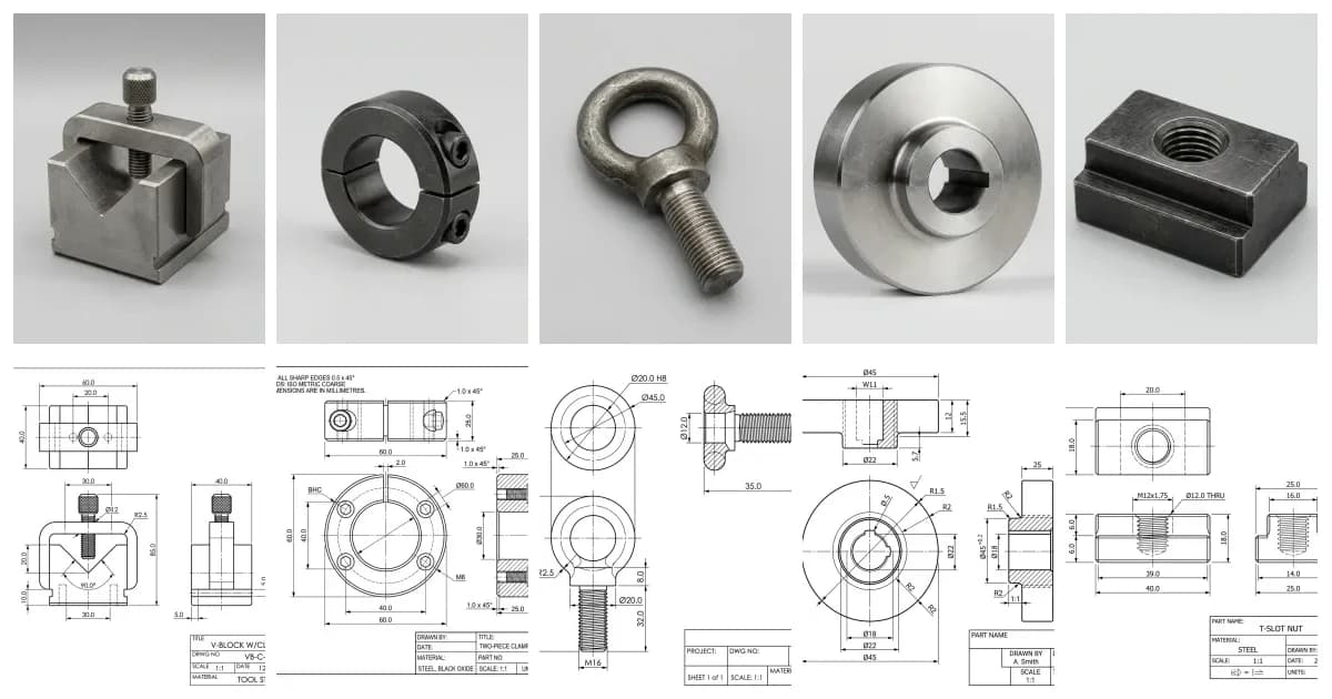
The drawings paired with the photos throughout this post are generated illustrations, not inspection-grade output. The point is the workflow, not the exact values. Always verify dimensions against the real part.
Where Grok stops and a real tool starts
Every prompt here works because it plays to what Grok is good at: reading an image, reasoning with Think mode, live research with sources, and code. The one thing it cannot do is produce accurate, measured geometry of your actual part. It cannot measure, it cannot hold a tolerance, and it cannot recover true scale from a single photo. Grok Imagine makes that boundary easy to miss, because it paints convincing blueprint-style pictures on demand, but the numbers on them are decoration. That is not a prompt you can write your way around; it is the boundary of the tool.
So the workflow that actually ships parts is a hand-off. Use Grok for the reading, the research and the review. Use a purpose-built image to CAD converter for the geometry: our photo to manufacturing drawing workflow turns a real part or image into a dimensioned drawing with DWG, DXF, SVG and PDF export, which is precisely the step a chatbot is missing. For the wider landscape of what each tool is for, see the best AI technical drawing tools.
Get the division of labour right and Grok stops being the chatbot that paints the prettiest fake blueprints and becomes what it should be: a sharp-eyed reader and the only drafting assistant with a live line to the world's standards and catalogues, sitting next to a tool that does the part it cannot.
Frequently asked questions
Can Grok create a technical drawing from a prompt?
Not a real, to-scale, dimensioned one. Grok Imagine will happily paint something that looks like a blueprint, but it is raster art with decorative numbers, not CAD geometry. What Grok can genuinely do is read a drawing you upload with its vision, plan views, datums and tolerances, research standards and catalogue parts live with cited sources, and write simple geometry as DXF text, SVG or an AutoLISP routine you run in AutoCAD. For a drawing a shop can cut from, the geometry has to come from a purpose-built tool.
Can Grok read an engineering drawing I upload?
Yes. Grok accepts images, so you can upload a drawing or a photo of a part and ask it to walk the views, decode symbols, extract dimensions into a table, or review the sheet the way a machine shop would before quoting. Like every chatbot, it reads with confidence even when it is wrong, so verify any exact value it lifts off the image before you quote or cut metal from it.
Can Grok Imagine make blueprints or CAD files?
No. Grok Imagine generates and edits raster images and video, so the best it can produce is a picture in the style of a blueprint. It cannot output DXF, DWG or any editable CAD geometry, and the dimensions it paints are invented. If you want geometry out of Grok, ask for code instead: DXF text, SVG or an AutoLISP script for simple shapes, or hand the job to a dedicated image-to-CAD tool.
Can Grok generate a DXF file or AutoLISP code?
Yes, for simple geometry. DXF is a text format, so Grok can write a minimal ASCII DXF with lines, circles and polylines that you save and import into CAD, and it is genuinely useful at writing AutoLISP routines that draw or automate inside AutoCAD. Keep it to basic profiles, check units and scale in a viewer before cutting, and let a purpose-built converter handle anything with real-world measurements.
Is Grok better than ChatGPT, Claude or Gemini for technical drawing?
Each has a different edge. Grok's is live search: it can check the current revision of a standard, find a matching catalogue part or confirm real stock sizes with cited sources while it works. Gemini usually reads a dense drawing image best, Claude is strongest on long drawing packs, careful reasoning and code, and ChatGPT has the broadest ecosystem. None of them can produce a manufacturing-ready drawing of your actual part; that step needs a purpose-built tool.