From TextA sentenceYour sizesA specA noteAny textto a technical drawing with AI


1,200+ reviews
Chosen for this example: M6 clearance hole drawn Ø6.6 (ISO 273, medium fit).
Text to technical drawing in three steps
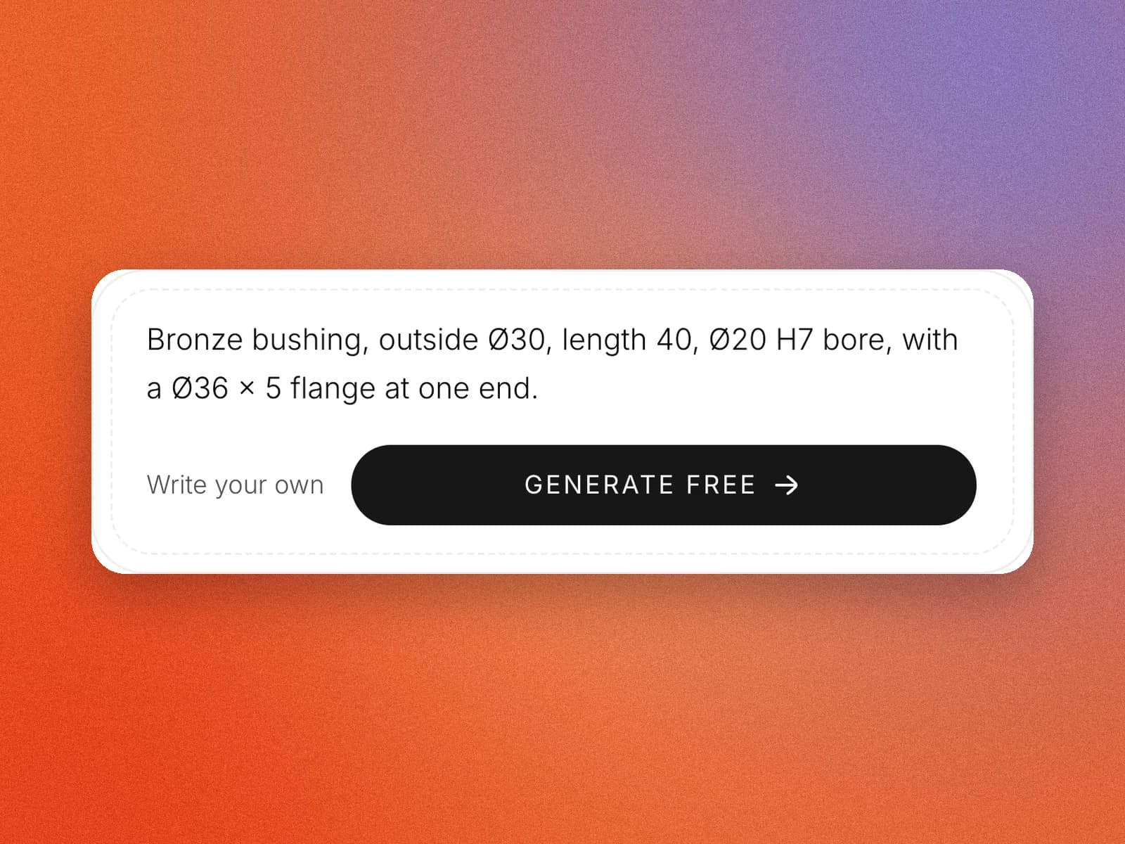
Describe the part
Type it the way you would tell a machinist: what the part is, its sizes and where the holes go.
- Millimetres or inches
- Threads, fits and bolt circles understood
- Six worked examples to start from
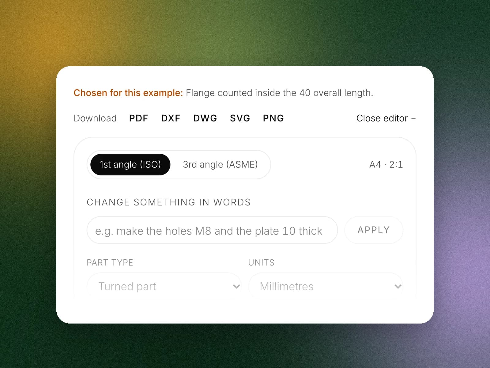
Check what was assumed
Anything you did not say is chosen to a standard and listed in plain words, so no number on the sheet is a surprise.
- An M6 clearance hole becomes Ø6.6 per ISO 273
- Change any size, or say the change in words
- Checks flag holes that break out of an edge
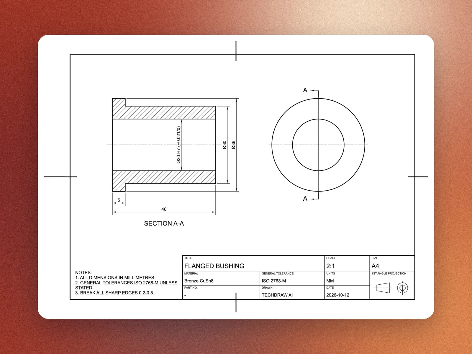
Download the drawing
A dimensioned sheet with true views, sections and a title block, computed from your numbers rather than drawn by an image model.
- PDF to send, DXF and DWG at true size
- ISO first angle or ASME third angle
- A cut-only DXF for laser parts
Drawings for what you describe
Three families, each drawn the way its shop reads it. Open one to see the sheet and edit it.
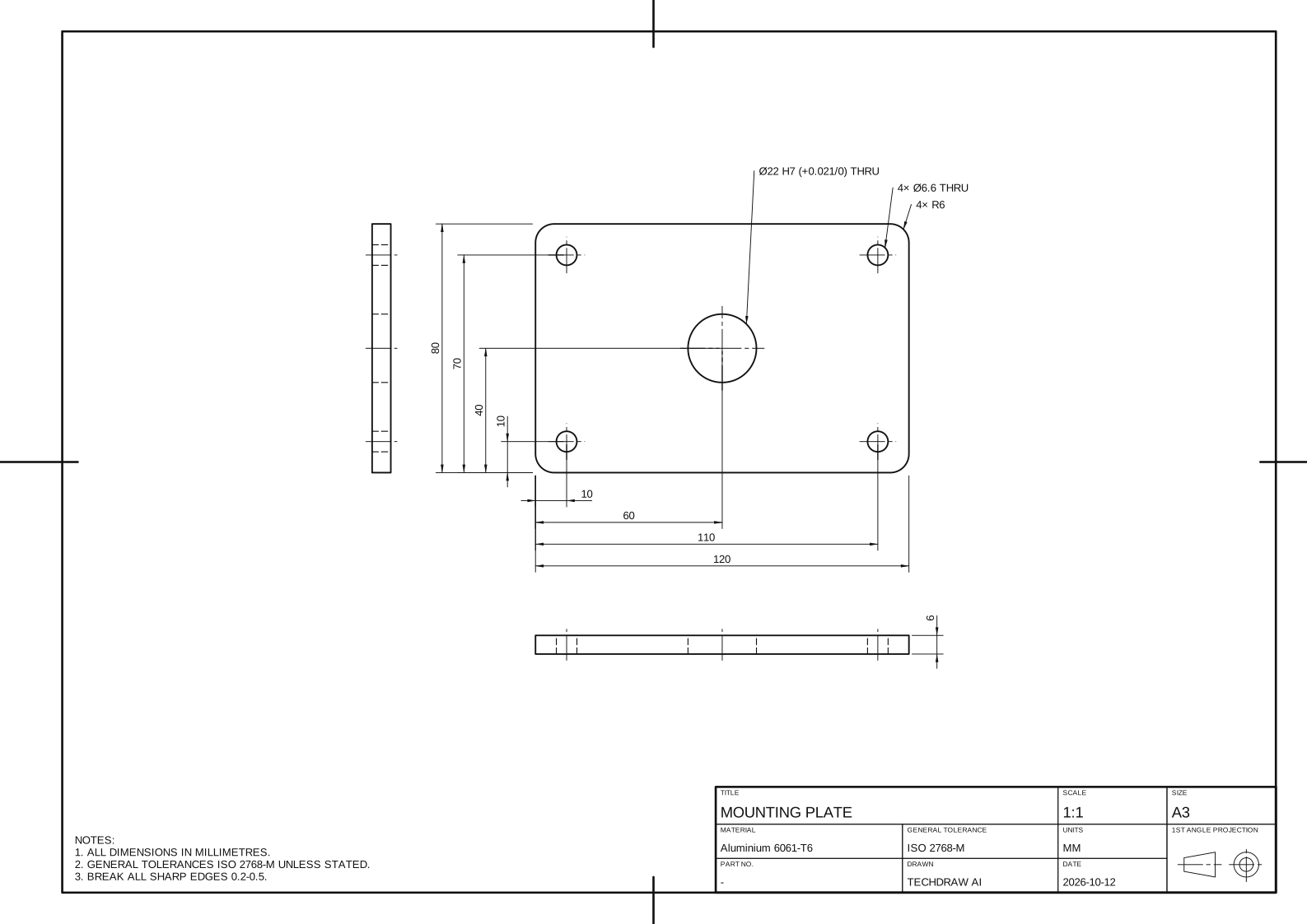
Plates and flat parts
Mounting plates, covers and gaskets with holes, threads, slots and pockets.
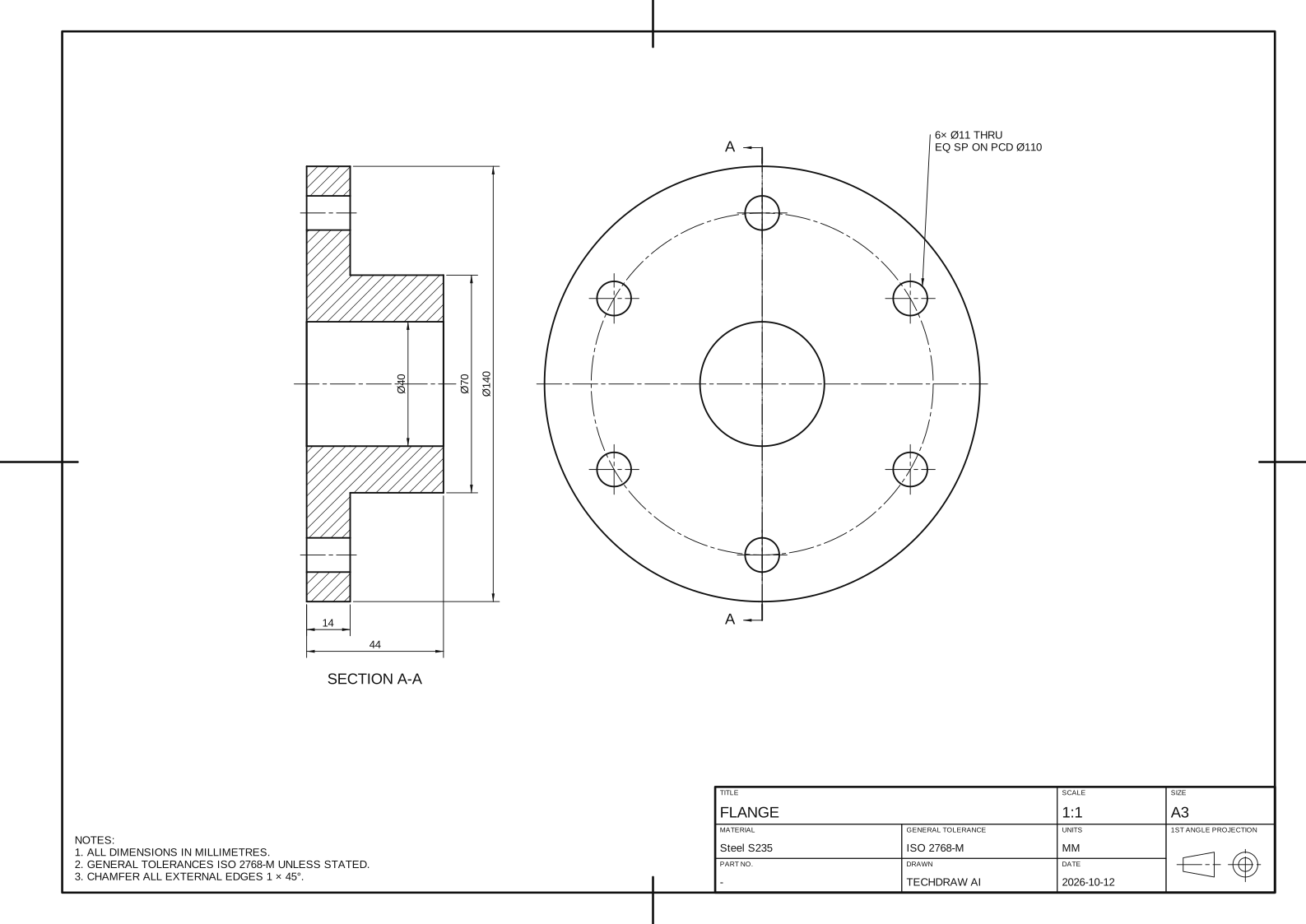
Turned parts
Shafts, flanges, bushings and spacers, drawn in full section with an end view.
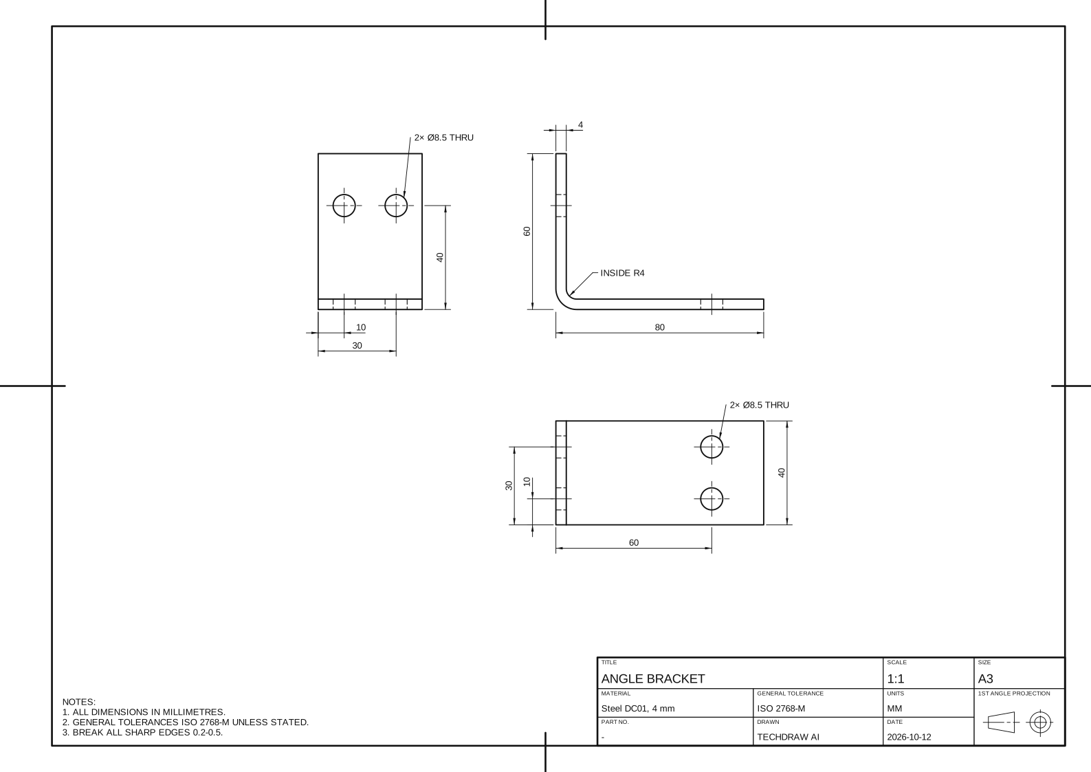
Angle brackets
Bent L-brackets with holes on either leg, each leg dimensioned in its own view.
Or skip the text. Anything else, from a cabinet to a casting, comes out of the photo generator instead.
The text to drawing tool that never invents a number
Most text to drawing tools hand your sentence to an image model and get back a picture with made-up dimensions and views that disagree. TechDraw AI reads the sentence into sizes and computes the drawing from them, so the sheet can be measured, checked and cut.
From a description
The language model only reads your sentence into sizes. The drawing is computed from them, so every view agrees and every number is yours.
From a photo
When the part already exists, a photograph beats a description. The photo generator drafts anything, not just three families.
From a CAD file
Already have the DXF? Check it, view it or convert it. These run in your browser and the file never leaves your machine.
156,000+ users can't be wrong. Let AI draft your next drawing.
Frequently asked questions
How do I turn text into a technical drawing?+−
Type the part and its sizes into the box, for example "steel plate 200 x 100 x 8, four M8 holes 15 from each corner", and press Generate. You get a dimensioned drawing with true views and a title block, ready to download as PDF, DXF or DWG.
Can AI make a technical drawing from a text description?+−
Only if it does not invent the numbers. Image models paint something that looks like a drawing with made-up dimensions. Here a language model only reads your sentence into sizes, and the drawing is computed from them, so every dimension is one you gave or one listed as an assumption.
What parts can it draw?+−
Plates and flat parts, turned parts (shafts, flanges, bushings, spacers) and angle brackets, with holes, threads, fits, slots and pockets. Gears, castings and freeform shapes are refused with a reason. For those, use the photo generator.
What if I leave a size out?+−
It is chosen to a standard, for example an M6 clearance hole becomes Ø6.6 per ISO 273, and listed under the box. Change it in words or in the size editor and the sheet redraws.
Is it free?+−
Yes. Describing a part and downloading need a free account, and no credits are used. Editing the sizes is unlimited and runs in your browser.
Which files do I get?+−
PDF, DXF, DWG, SVG and PNG. DXF and DWG are written at true size in millimetres even when the sheet is at 1:2, so the part measures correctly in AutoCAD, Fusion or SolidWorks. Flat parts also get a laser DXF with the cut contours only.
Does it follow drafting standards?+−
Yes: ISO 128 line types, first or third angle projection, baseline dimensions, ISO 6410 threads, full sections for turned parts and ISO 286 fits with their limits. General tolerances default to ISO 2768-m.
How is this different from the photo generator?+−
Different starting point. Photograph a part that exists; describe one that does not yet, or whose sizes you already know.