Orthographic Drawing Maker
Make an orthographic drawing from any 3D model: three aligned views, hidden lines, dimensions, ready to print or open in CAD.
Drop a file here. It never leaves your browser.
No sign-up · no upload · no watermark · true millimetres · STL, STEP, IGES, OBJ, 3MF and PLY in · SVG, DWG, PDF one click away
Want one flat profile instead of views? STL to DXF · Starting from a photo, not a model? Image to DXF
Trusted by


Orthographic drawing examples
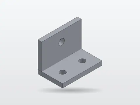
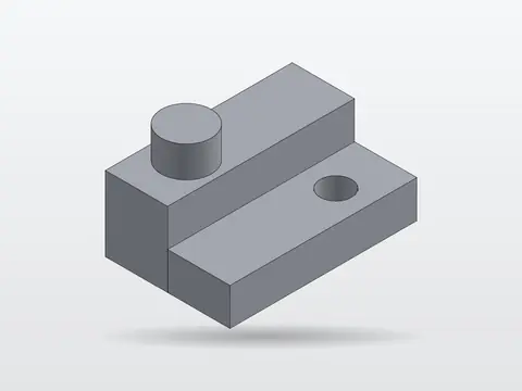
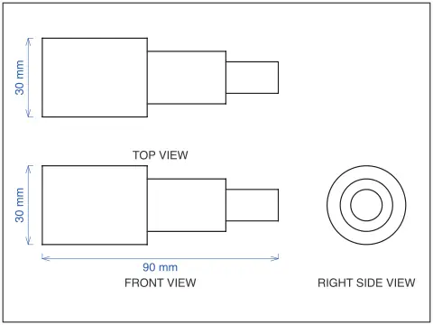
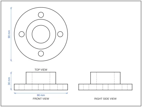
Four parts and the drawings this page made from them, in third angle: front, top and right side, hidden edges dashed, overall dimensions in millimetres. None of these is an illustration — each drawing is the tool's own output for the model beside it, and the stepped block is the sample part you can load above.
 Model
Model Drawing
 Model
Model Drawing
 Model
Model Drawing
 Model
Model Drawing
How to make an orthographic drawing from a 3D model
Load a 3D model
Drop in an STL, STEP, OBJ, 3MF, PLY or IGES file, or click the sample part if you only want to see how it works. It is read in the browser and never uploaded.
Pick the views and the angle
Front, top and right side are on by default. Add the rest if the part needs them, and choose third angle or first angle. The views line up either way.
Check the lines, then download
Hidden edges come out dashed, overall dimensions are added, and the corner-angle slider decides what counts as an edge on a curved surface. Then download DXF, SVG, DWG or PDF at true size.
What an orthographic drawing has to contain
Views, lines, dimensions, a title block, a projection symbol. The views are the fewest that describe the part without leaving a question — three for most parts, two for a turned one, one plus a thickness note for a flat plate — and they are aligned, so a hole in the front view sits directly under its circle in the top view. The lines come in three kinds and the eye reads them without thinking: visible edges thick and solid, hidden edges thin and dashed, centre lines through every hole and cylinder in long-short dashes.
Dimensions go on the view where the feature shows its true shape, once each, never repeated, with the overall width, height and depth first. The title block carries the part name, material, scale and units. And the small truncated-cone symbol says whether the views are laid out in first or third angle, which decides whether the right side view is on the right or the left — how to dimension it and how to read one are their own guides.
The maker above does the views, the line types, the alignment, the overall dimensions and the labels, from any model you give it, and leaves you the feature dimensions and the title block. Those are the two things a person has to decide, because they depend on what the part is for.
What actually happens to your model
The file is read into triangles in your browser — meshes directly, STEP and IGES through the OpenCascade kernel compiled to WebAssembly. Vertices are welded and every edge is found with the two faces on either side of it. An edge is a corner if its faces meet at more than the slider angle; an edge is a silhouette, for a given view, if one face turns towards you and the other away. Those are the candidate lines.
Then, for each view, every triangle is drawn into a depth buffer, and every candidate line is walked in sub-pixel steps: each step is either in front of what the buffer holds or behind it. Runs in front become solid polylines; runs behind become dashes. The buffer is biased away from you by the slope of each face across a pixel, so a face can never hide its own edge — the mistake that makes cheap hidden-line code speckle. Lines that coincide with a visible line are drawn once.
What it will not do is guess. Fillets that are smaller than a pixel of the depth buffer can lose their tangent edges; open meshes are reported rather than silently closed; feature dimensions are left to you. Every shipped change is run against a cube, a cylinder, a stepped block with a hole and a hundred-thousand-triangle sphere, and the visible and hidden lengths are checked against what a person would draw. Wanting one flat profile rather than views is a different job — that is the STL to DXF section tool.
How we check the views are right
A drawing is right when the solid lines add up to exactly the edges you would see and the dashed lines to exactly the edges you would not. So the check builds parts whose drawings are known by hand, runs them through the same code this page runs, and adds up the line lengths. The numbers below are what it reports today.
A 20 mm cube: 80.0 mm seen, 0.0 hidden
Each view is one square. The far edges sit exactly behind the near ones and are drawn once, not dashed underneath — 60 mm of hidden line would have meant a coincident-edge bug, and it did, until it was fixed.
A Ø20 × 30 cylinder: 99.99 of 100 mm
Front view: two rims and two silhouettes, found per view rather than stored in the file. Top view: one closed circle of 62.17 mm against a true circumference of 62.83, 1% short from the 96-facet mesh, not the projection.
The sample block: 23.97 of 24 mm hidden
The through hole is two dashed lines of 12 mm in the front view and a solid circle in the top view, where it is seen. A 100,000-triangle sphere projects to three views in 0.7 s, with its outline 314 mm round.
About the output formats
DXF (Drawing Exchange Format) is a CAD data file format developed by Autodesk, first released in December 1982 with AutoCAD 1.0 to enable interoperability between AutoCAD and other programs. The format exists in two variants: ASCII DXF, a human readable text file organised into sections (HEADER, TABLES, BLOCKS, ENTITIES, OBJECTS), and binary DXF for faster parsing. Each geometric entity, including lines, arcs, circles, polylines, splines, text, dimensions and 3D solids, is described by group codes paired with values that specify coordinates and properties. DXF versions evolve alongside AutoCAD releases, adding support for new features with each edition. One major advantage is universal CAD compatibility, since DXF is supported by virtually every CAD, CAM and engineering application across all platforms, which makes it the most widely accepted exchange format for technical drawings. The ASCII variant is another strength, because drawings can be inspected, debugged and generated programmatically with text tools or scripts. DXF serves as a critical bridge that lets architects, engineers and manufacturers share precise drawings regardless of which software each party uses, and it remains the standard for cross platform CAD data exchange.
- Developer:
- Autodesk
- Initial release:
- December 1982
Frequently asked questions
What is an orthographic drawing?
A drawing of an object made of two or more views taken square-on to its faces, laid out so the views line up, with the edges you can see drawn solid and the edges behind the surface drawn dashed. It is the standard way of describing a part to be manufactured, because every dimension can be measured off a view at true size, which no perspective drawing allows.
How do I draw an orthographic drawing by hand?
Pick the front view first: the one that shows the most about the shape, usually the longest side. Draw it. Project construction lines straight up from it and draw the top view on those lines, the same width. Project lines straight across and draw the side view, the same height, and carry the depth from the top view across with a 45° mitre line. Then go over it: visible edges solid and thick, hidden edges dashed and thin, centre lines through every hole and cylinder in long-short dashes. Only then add dimensions, and put each one on the view where the feature shows its true shape.
What does a good orthographic drawing contain?
The fewest views that describe the part completely, aligned with each other; the three line types used correctly — visible, hidden and centre; overall dimensions plus one dimension for every feature, each given once; a title block with the part name, material, scale and units; and the projection symbol saying whether it is first or third angle. Miss the last and someone abroad will build it mirrored.
Is it free, and do I need an account?
Free, no watermark, no limit on the number of drawings, and no account to download. The model is read in your browser and never uploaded; the views are computed on your own machine, which is also why it works with the network cable pulled once the page has loaded.
Which file formats can I upload?
STL, OBJ, 3MF and PLY meshes, and STEP (.step, .stp) or IGES solids straight out of SolidWorks, Fusion, Inventor, Onshape or FreeCAD. STEP is read by the same OpenCascade geometry kernel FreeCAD uses, compiled to WebAssembly, so the file does not need converting first.
Which views does it make?
The three principal views by default — front, top and right side — and any of the other three (left, rear, bottom) plus an isometric view on request. They are laid out in third-angle projection (the American convention: top view above the front) or first-angle projection (the ISO convention: top view below the front), and they line up exactly, so a feature in one view sits directly across from itself in the next.
How does it know which lines are hidden?
It does what a graphics card does: every triangle of the model is drawn into a depth buffer for each view, and then every candidate edge is walked point by point and compared against that buffer. Points in front of the surface become solid lines, points behind it become dashes. Edges that coincide with a visible edge are drawn once rather than dashed underneath it, which is how a draughtsman would treat them.
Why does my cylinder come out with stripes, or my chamfer vanish?
A curved surface is stored as many small flat facets, and the tool has to decide which of the edges between them are real corners. It draws an edge as a corner when the faces meet at more than the angle on the slider, 25° by default. A coarse STL with big facets can trip that, so raise the angle and the stripes go; a very shallow chamfer can fall under it, so lower the angle and it comes back.
Is the drawing at the right scale?
The DXF, DWG and SVG are written in real millimetres at 1:1, so a 60 mm part measures 60 mm in AutoCAD, Inkscape or Fusion. The PDF is 1:1 on a page that fits the drawing, or scaled to fit A4, A3 or Letter with the scale printed in the corner so nobody measures a shrunken print and believes it.
Are the dimensions complete?
No, and no automatic tool's are. It adds the three overall dimensions — width, height and depth — which is what a drawing must carry before anything else. Hole positions, diameters, fillets and tolerances are yours to add in CAD, and you can switch the overall ones off if your CAD program will re-dimension the views anyway.
My model is a scan or an open surface. Will it work?
It will draw it, and it will tell you the mesh is open. Hidden-line removal assumes a closed solid; along a hole in the mesh there is no surface to hide anything, so lines near the gap may show that should not. Running the file through the STL repair tool first usually closes it.
Can I use it for homework?
Yes, and please check the result rather than copying it: the point of the exercise is to be able to draw the views yourself. Load the sample part, hide the drawing, draw your own three views on paper, then compare. The differences are where the learning is.
Related tools and guides
Same tool, other name
From a photo instead
All 3D file tools
Outputs: DXF, SVG, DWG, PDF · all at true size