
First angle and third angle projection arrange the same orthographic views on opposite sides of the front view. In third angle the top view sits above the front view; in first angle it sits below. Nothing else changes: same geometry, same dimensions, same tolerances. The only reliable way to tell which one you are holding is the truncated cone symbol on the sheet, and the part of that symbol that matters is not the part most guides point at.
Our articles are still written by humans!
Get human written articles in your Google feed.


The short answer
Both methods are orthographic projection: the object is viewed square on, along axes at right angles, and each view is drawn true to scale with no perspective. What differs is where the resulting views are placed on the sheet.
Third angle projection imagines the projection plane between you and the object, as though the object sits inside a glass box and each face is drawn on the glass nearest to it. Unfold the box and every view lands on the side it was seen from. Look down at the part, and the resulting view goes above the front view.
First angle projection puts the object between you and the plane, so each view is projected through the object onto the plane behind it. Unfold that and every view lands on the opposite side. Look down at the part, and the resulting view goes below the front view.
The symbol, and what most guides get wrong
Every drawing that uses either method is supposed to declare it with a symbol, normally in or beside the title block. The symbol is two views of a hollow truncated cone: a pair of concentric circles, which is the cone seen end on, and a trapezoid, which is the cone seen from the side.
The symbol is not an arbitrary badge. It is a small drawing of a cone projected using the very method it names, so it demonstrates the convention rather than just labelling it.
If you memorise “circles on the left means third angle” you will be right about half the time and confidently wrong the rest, which is worse than not knowing. The taper is the invariant.
What each method does to the layout
The same six views, placed two ways
The rear view is the one exception people trip on: it sits at the far end of the horizontal row in both methods, so it is not a reliable tell.
Why there are two conventions
The names come from the four quadrants formed by a vertical and a horizontal plane. Put the object in the first quadrant, above the horizontal plane and in front of the vertical one, and you get first angle. Put it in the third, below the horizontal plane and behind the vertical one, and you get third angle. The second and fourth quadrants are not used because the unfolded views would overlap.
Both survived because both were entrenched before anybody standardised anything, and because each has a defensible argument. Third angle is usually called the more intuitive of the two, since a view appears where you would expect it. First angle has its own logic for large assemblies, where the views unfold away from the object in the direction you walk around it. Neither argument is strong enough to have killed the other in a century of trying.
Why country is not a reliable guide
The usual rule of thumb is that first angle is European and third angle is American. As a prior it is fine. As a decision procedure it is not.
- First angle is the ISO default and normal across Europe, India, China and much of Asia.
- Third angle is standard in the United States and Japan, and is what ASME Y14.3 specifies.
- Mixed in practice: Canada and Australia, where published sources genuinely disagree with each other, which tells you something in itself.
More importantly, drawings travel and templates travel further. A CAD template copied from a parent company, a supplier detailing to their own house standard, a legacy drawing reissued without review: any of these puts a first angle sheet on an American desk or the reverse. That is precisely why both ISO and ASME require the symbol. The symbol exists because the country rule is not trustworthy.
How to tell in ten seconds
- Look for the cone symbol, usually in or next to the title block. Read the taper. Away from the circles is first angle, toward them is third.
- No symbol? Look for the words. Many sheets spell it out in the title block as
THIRD ANGLE PROJECTIONor as a projection field. - Still nothing? Find an asymmetric feature. A boss, a step, a counterbore, anything that exists on one side and not the other. Work out where that feature appears in the second view. If the feature you can see on the right of the front view appears on the right of the side view, you are in third angle.
- Symmetrical part with no symbol? Then it does not matter for making the part, but ask anyway, because the next revision may not be symmetrical.
What breaks when it is read wrong
For a symmetrical part, nothing at all, which is exactly why the mistake survives long enough to get expensive. The failure mode is specific: the part comes out mirrored along the axis that the misread view controls.
- A step on the left of a shaft is turned on the right.
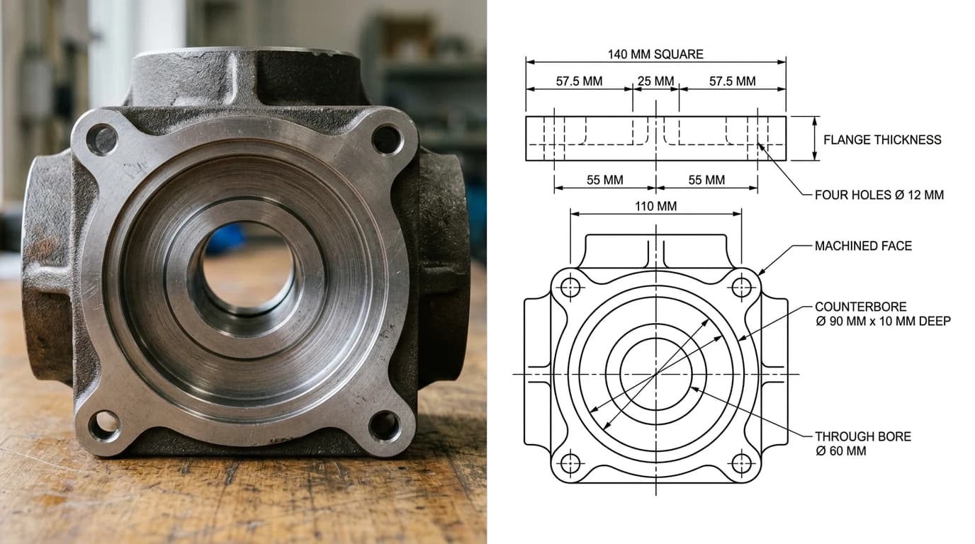
- A counterbore lands in the opposite face.
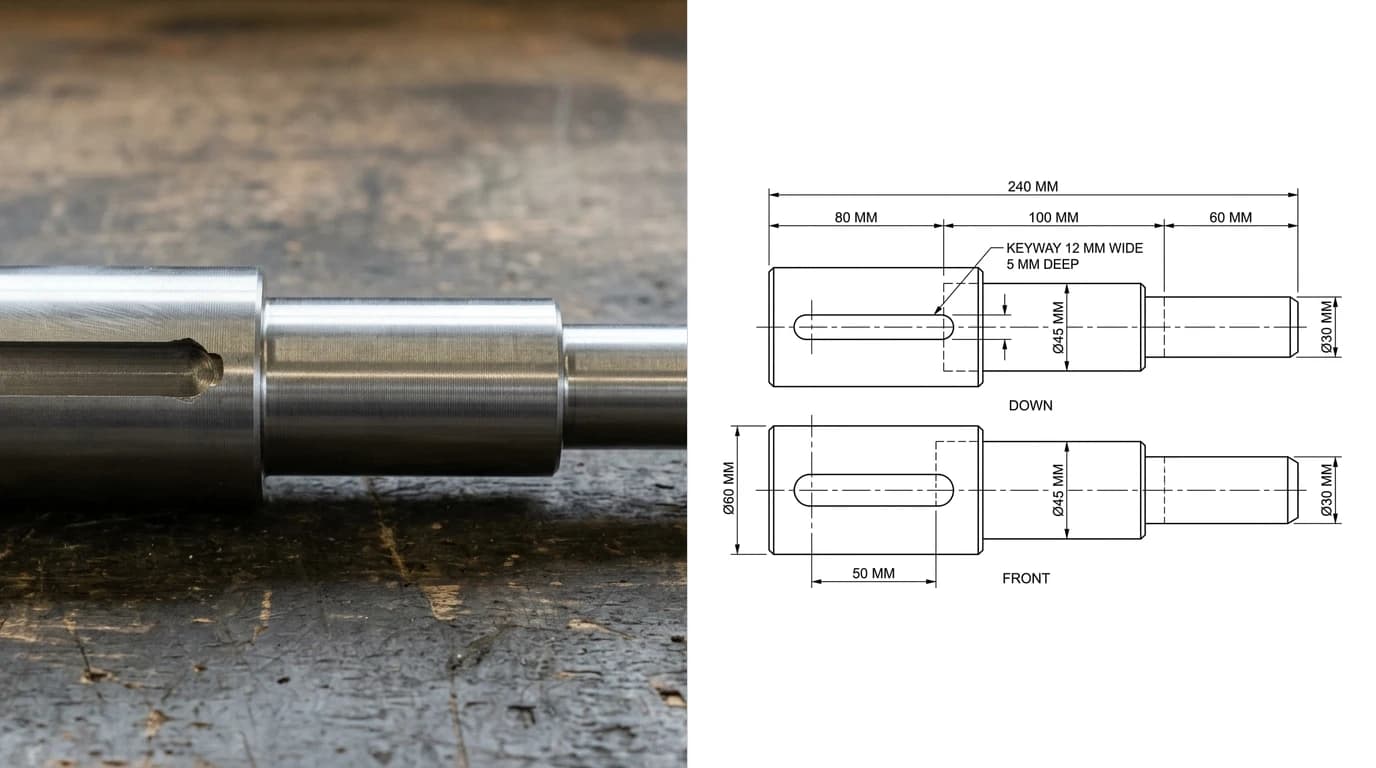
- A keyway ends up on the wrong end.
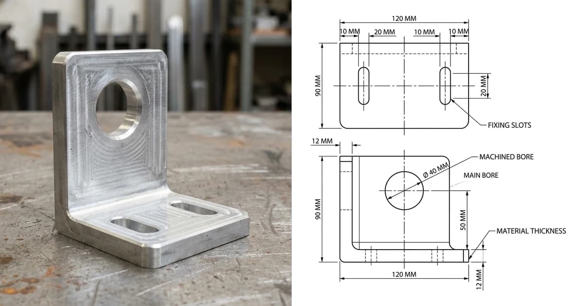
- A bracket is made as its own mirror image and will not bolt to anything.
Every dimension on the drawing was still correct, and the part still measures right. That is what makes it a quiet failure: inspection against the dimension list passes, and the problem only surfaces at assembly. It is the same category of error as a DXF that imports at the wrong scale, where the geometry is fine and one global assumption was not.
The defence is boring and it works: state the projection on every sheet, put the symbol next to the title block, and when you receive a drawing without one, ask before you cut. For the wider set of checks a sheet has to pass, how to read a technical drawing covers the view conventions and how to dimension a technical drawing covers what goes on them.
What the standards say
Where each convention is written down
The point worth carrying away from the standards is the one they agree on: neither method is correct in preference to the other, and the obligation the standards impose is not to pick a side but to declare which side you picked. A drawing that states its method is unambiguous in either convention. A drawing that does not is ambiguous in both.
Where the pictures in this article came from
Worth being explicit, since it bears on whether you should trust them. The two diagrams, the symbol and the view grid, are drawn by hand as vector graphics. They carry the article's factual claims, so they are exact by construction rather than by luck.
The photographs and the drawings beside them are real output: a photograph of a part, and the dimensioned orthographic drawing our own pipeline projected from it. We built TechDraw AI to do exactly that, which meant deciding early which convention to emit and being able to produce either. If you want the route rather than the theory, JPG to CAD and image to DWG walk it through, and getting dimensions from a photo is honest about what a photograph cannot tell you: a flat image carries shape and proportion, the scale comes from one measurement you supply, and the projection method comes from the template you are drawing to.
To see the two conventions on a part of your own rather than a diagram, the orthographic projection generator takes an STL or STEP, projects the front, top and side views with the hidden lines dashed, and lays them out in either angle with a click. It runs in the browser and is free. Switching it between the two is the quickest way to make the placement rule stick.
Watch: Unfolding the box vs tipping it over
GD&T Basics animates the two layouts with a simple box. Third angle is shown as unfolding the box, so every view lands on the side it was seen from; first angle is shown as tipping the box over, so each view lands on the opposite side. It then ties each layout back to its cone symbol. That makes the layout table above concrete in four minutes. It is a sample lesson from the channel's paid course, and it teaches from the ASME side, where third angle is the default.
Frequently asked questions
What is the difference between first angle and third angle projection?
Both arrange the same orthographic views, but on opposite sides of the front view. In third angle projection each view is placed on the side it is seen from, so the top view sits above the front view and the right-side view sits to the right. In first angle projection the object is imagined between the viewer and the projection plane, so the views come out reversed: the top view sits below the front view and the right-side view sits to the left. The geometry and dimensions are identical; only the placement changes.
How do you tell first angle from third angle projection?
Find the truncated cone symbol, normally near the title block, and look at which way the cone tapers relative to the two concentric circles. If the narrow end of the cone points away from the circles it is first angle. If the narrow end points toward the circles it is third angle. The side the cone sits on does not matter, and neither does the country the drawing came from.
What does the first angle projection symbol look like?
A pair of concentric circles beside the side view of a truncated cone, drawn as a trapezoid. In the first angle symbol the trapezoid's narrow end faces away from the circles. The symbol is derived by projecting a hollow truncated cone using the method it represents, so the symbol is itself an example of the convention it names.
Which countries use first angle projection?
First angle is the ISO default and is normal across Europe, India, China and much of Asia. Third angle is standard in the United States and Japan under ASME Y14.3. Canada and Australia are mixed in practice. Country is a useful prior but not a rule, because multinational suppliers, imported CAD templates and legacy drawings all travel, which is why every drawing is required to carry the symbol.
Is first angle or third angle projection better?
Neither. ISO 5456-2 grants both equal status and either may be used provided the drawing states which. Third angle is often called more intuitive because each view appears on the side it is seen from, and first angle is defended as more natural for large assemblies where views unfold away from the object. The engineering content of the two drawings is identical.
What happens if you read a drawing in the wrong projection?
For a symmetrical part, nothing. For an asymmetric one, the part comes out mirrored along the axis the misread view controls: a step on the left becomes a step on the right, a counterbore lands in the opposite face, a keyway ends up on the wrong end of the shaft. It is a quiet failure, because every dimension is still correct and the part still looks plausible until it will not assemble.
Does the projection method change the dimensions?
No. Projection method controls only where each view is placed on the sheet. Every dimension, tolerance, section and callout is identical between a first angle and a third angle drawing of the same part. That is why a drawing can be converted between conventions by rearranging views without touching any number.
What projection does CAD software use by default?
It depends on the template rather than the software. Most CAD packages ship with both and pick the default from the drawing standard set in the template, so a SolidWorks or AutoCAD file can produce either. Because the default is inherited from a template that may have been copied between companies and countries, the setting in your file is not evidence of anything. Read the symbol on the sheet you were sent.