
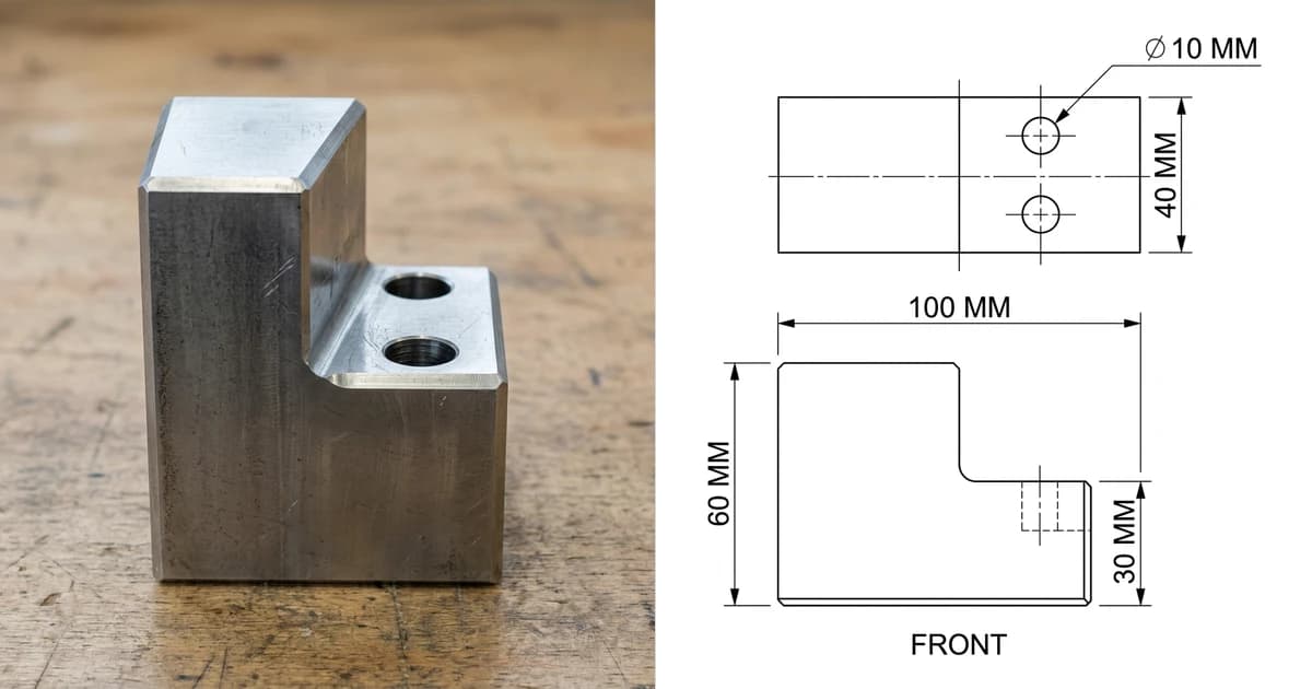
CAD stands for computer-aided design: using software to create, change and document a design as exact geometry instead of drawing it by hand. That is the whole definition. What trips people up is everything around it, the difference between design and drafting, why there are a dozen kinds of CAD software, what a “CAD file” is and is not, and where AI has and has not changed the job. This is the plain-language version, written for someone who has just been asked for “the CAD” and wants to know what they are actually being asked for.
Our articles are still written by humans!
Get human written articles in your Google feed.
The short answer
CAD is computer-aided design: software that lets you draw and model with exact coordinates, so a line is a line from (0,0) to (100,0), a hole is a circle of radius 5 at a known centre, and a part is a solid with a real volume. Because the geometry is exact, the computer can dimension it, measure it, check it for collisions, drive a machine tool from it, and let you change one number and have the rest update. That precision and editability is what separates CAD from a drawing app, and it is why every manufactured object and every building you see today passed through CAD on the way to existing.
The term covers two overlapping jobs. Computer-aided drafting is the older, narrower one: making technical drawings, the 2D sheets with views, dimensions and a title block. Computer-aided design is the wider one: modelling the part or building itself, usually in 3D, and then producing the drawings from the model. When someone says “CAD” without qualifying it, they mean the software category as a whole.
What CAD stands for: design or drafting?
Both, and the confusion is historical. The first CAD systems were digital drawing boards: you drew lines and arcs on a screen instead of vellum, so “computer-aided drafting” was the honest name. As the software learned to model solids in 3D, the D drifted toward “design”, and the compromise CADD, computer-aided design and drafting, appeared to keep both. In 2026 the practical split is by role, not by acronym:
- A CAD drafter or detailer produces drawings: shop drawings, fabrication drawings, plan sets. Their tool is often 2D (AutoCAD, BricsCAD, DraftSight) or the drawing module of a 3D package.
- A designer or engineer owns the model: they decide the geometry, run the analysis, and hand off a 3D file plus drawings.
Whichever end you sit at, the output that leaves the building is still, overwhelmingly, a dimensioned 2D drawing. If you want to see why that is, why machine shops still want 2D drawings makes the case, and how to read a technical drawing shows what is on one.
A short history of CAD
You do not need the history to use CAD, but a few dates explain why the landscape looks the way it does.
- 1963, Sketchpad. Ivan Sutherland's PhD project at MIT Lincoln Laboratory, drawn with a light pen on the TX-2 computer. It is the ancestor of every CAD program and, arguably, of the graphical user interface.
- 1964, DAC-1. General Motors and IBM put a production design system on a mainframe. Through the 1960s and 70s CAD lived only inside aerospace and car companies that could afford it.
- 1977 to 1978, CATIA and Unigraphics. Dassault's CATIA (aircraft surfaces) and Unigraphics, now Siemens NX, are the roots of today's high-end 3D packages.
- 1982, AutoCAD. Autodesk shipped 2D CAD that ran on a personal computer. This is the moment CAD reached small firms, and it is why the DWG format is everywhere; the story of that file is in what is a DWG file.
- 1987, Pro/ENGINEER. PTC introduced parametric, feature-based solid modelling: change a dimension and the model rebuilds. Every mainstream 3D CAD tool since works this way.
- 1995 to 1999, mid-range 3D. SolidWorks (1995), Solid Edge (1996) and Autodesk Inventor (1999) brought parametric 3D to Windows PCs and ordinary engineering budgets.
- 2013 onward, cloud. Fusion 360 and Onshape moved CAD into the browser and subscription, and made free personal tiers normal.
The kinds of CAD
“CAD software” is a category, not a product, and the members store fundamentally different things. Picking the wrong kind is the most common beginner mistake, so here is the map.
2D drafting CAD
Lines, arcs, circles, text and dimensions on a flat sheet, organised in layers. This is the digital drawing board. AutoCAD, AutoCAD LT, BricsCAD, DraftSight, and the free LibreCAD and QCAD live here, and DWG and DXF are their file formats. Still the right tool for plan sets, schematics, flat parts for laser and plasma cutting, and any drawing you would once have done on paper.
3D solid modelling, parametric
You sketch a 2D profile, give it dimensions, extrude or revolve it into a solid, then add features: holes, fillets, patterns. Every feature remembers how it was made, so changing a dimension rebuilds the part. SolidWorks, Inventor, Fusion 360, Creo, NX, Solid Edge, Onshape and FreeCAD are parametric modellers. This is the workhorse of mechanical design.
3D solid modelling, direct
Push and pull faces without a feature history. Faster for editing someone else's model or a STEP file with no history, weaker when you need the design to update itself. Most parametric packages now include a direct mode; SpaceClaim and Shapr3D lean this way.
Surface and freeform modelling
For shapes defined by curvature rather than by flats and holes: car bodies, consumer products, aircraft skins. Rhino, Alias and the surfacing modules of CATIA and NX. Meshes (triangles rather than exact surfaces) belong to Blender and to 3D scanning and printing, which is why STL is a mesh format and not a CAD format in the strict sense.
BIM
Building Information Modelling, Revit and ArchiCAD, models a building as walls, doors and ducts that know what they are, not as lines. It grew out of CAD and still exports DWG, but it is its own discipline with its own file formats (RVT, IFC).
Kinds of CAD, what they store, and typical software
What a CAD file actually is
Here is the misunderstanding we see most often, and it is worth being blunt about. Someone asks a supplier for “the CAD file”, receives a PDF of the drawing, and thinks the job is done. It is not. A PDF, a JPG or a screenshot holds a picture of a drawing. A CAD file holds the drawing itself: every line as coordinates, every circle as a centre and radius, every dimension as an object attached to the geometry it measures, plus layers, units, blocks and the settings that make it editable. Open a CAD file in a CAD program and you can measure it, change it, and cut from it. Open a PDF and you can look at it.
Because CAD stores geometry, a CAD file always carries a unit and a scale of one: the part is drawn full size and only the printed sheet is scaled. Most import problems, a part arriving 25.4 times too big or a laser file that cuts tiny, are units problems, not broken files.
Common CAD file types and what each one holds
Who uses CAD
Almost every discipline that makes physical things. Mechanical engineers and product designers model parts and assemblies. Architects and structural, civil and MEP engineers produce building drawings and, increasingly, BIM models. Fabricators, machinists and detailers turn design intent into shop drawings, and what are shop drawings explains that hand-off. Surveyors, landscape architects, electrical designers, jewellers, furniture makers, sign shops and 3D-printing hobbyists all use some flavour of it. The common thread is that at some point a drawing with real dimensions has to leave the screen and be built, and CAD is where that drawing comes from.
CAD vs CAM vs CAE vs BIM
Four acronyms that travel together and get mixed up:
- CAD designs the geometry.
- CAM, computer-aided manufacturing, turns that geometry into toolpaths and G-code for a CNC machine, laser or 3D printer. Fusion 360 and NX bundle CAM; Mastercam and LightBurn are standalone examples.
- CAE, computer-aided engineering, analyses the model: stress, heat, flow, vibration. Ansys and the simulation modules of the big CAD packages.
- BIM is CAD for buildings with data attached to every element, and a shared model rather than a stack of drawings.
A part typically goes CAD (model it), CAE (check it), then either drawing plus CAM (make it) or BIM coordination (build it). CAD is the first step and the source of truth for the others.
How to start with CAD
- Decide 2D or 3D. Flat parts, plans and schematics: start in 2D. Parts with real thickness that fit other parts: start in 3D and draft drawings from the model.
- Pick a free tool. LibreCAD or QCAD for 2D, FreeCAD or Onshape's free plan for 3D, Fusion 360 for personal use if you want CAM in the same package. Our round-up of the best free CAD programs compares them properly.
- Learn the drawing conventions before the software. Views, dimensioning, tolerances and projection are the same in every package, and they are what a shop actually reads. How to make a technical drawing and how to dimension one are the two to read first.
- Model something real and get it made. A bracket, a spacer, a laser-cut plate. Nothing teaches CAD like a part coming back wrong because of a dimension you skipped.
How AI is changing CAD
Honestly, in three different ways, and it helps to keep them apart because the hype blurs them.
- Text to CAD is early. Describe a part in words and get a model back: the demos are impressive, the geometry is usually approximate, and nothing you would send to a machine without redrawing. Useful for concepts, not yet for production.
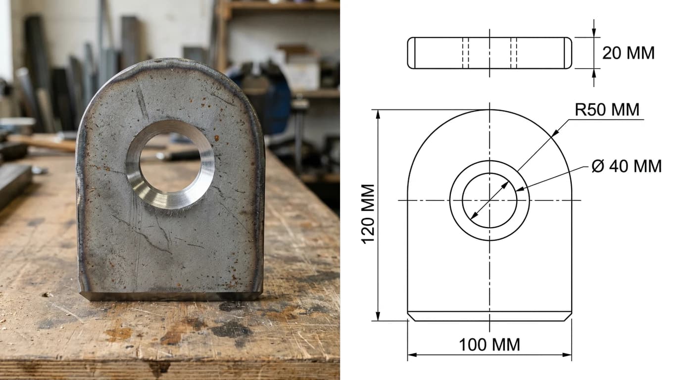
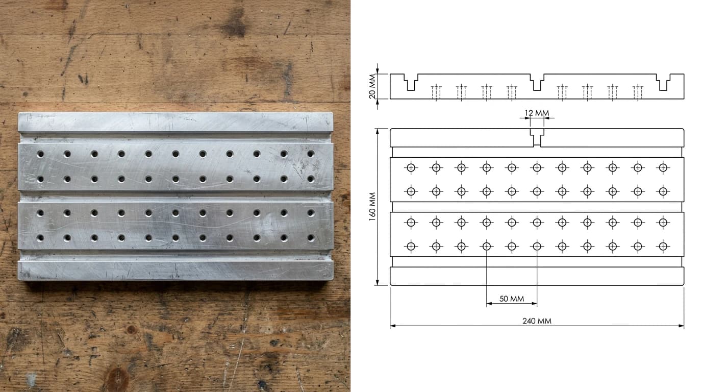
- Image to CAD works, within limits. From a photograph or scan of a flat or simple prismatic part, current tools produce a dimensioned 2D drawing that exports as DWG or DXF and opens in any CAD program. That is what TechDraw AI does, and both figures in this article are its output. It replaces the first hour of measuring and drawing, not the engineer. The detail is in AI image to CAD and the image to CAD converter.
- Assistants inside CAD are real but modest. Chatbots write AutoLISP and Fusion scripts, explain a drawing, and check a drawing for missing dimensions, and CAD vendors are adding assistants of their own. What none of them do yet is take responsibility for the geometry. A comparison of what is genuinely usable today is in the best AI technical drawing tools.
Upload a photo or image of a part and get a dimensioned drawing that exports as DWG or DXF.
Try image to CADFrequently asked questions
What does CAD stand for?
CAD stands for computer-aided design. You will also see it expanded as computer-aided drafting, and the longer form CADD, computer-aided design and drafting, covers both. In every case it means using software to create, modify and document a design as precise geometry, in 2D or 3D, instead of drawing it by hand.
What is CAD used for?
CAD is used to design and document almost anything that gets manufactured or built: machine parts, products, buildings, bridges, ships, aircraft, furniture, sheet-metal enclosures, circuit board outlines, and the fixtures and tooling that make them. Its outputs are 3D models for simulation and machining, and 2D drawings with dimensions and tolerances that a workshop or a site crew builds from.
What is the difference between CAD and drafting?
Drafting is the making of technical drawings: views, dimensions, notes and a title block on a sheet. Design is the wider job of working out what the thing is and how it works. Historically CAD software started as computer drafting, a digital drawing board, and grew into 3D design tools. Today most packages do both: you design a 3D model, then draft 2D drawings from it. Someone described as a CAD drafter usually produces the drawings; a designer or engineer usually owns the model.
What is a CAD file?
A CAD file is a file that stores geometry as objects with coordinates and properties, plus the layers, dimensions and metadata that make it a design rather than a picture. Common CAD file types are DWG and DXF for 2D drawings, STEP and IGES for exchanging 3D models between programs, native part files such as SLDPRT, IPT and F3D, and mesh formats such as STL, OBJ and 3MF for 3D printing. A PDF or JPG of a drawing is not a CAD file, because it holds pixels or printed lines rather than editable geometry.
What is the most common CAD software?
For 2D drafting, AutoCAD and its DWG format are the most widespread, which is why so many free and paid alternatives read DWG. For 3D mechanical design the big names are SolidWorks, Autodesk Inventor and Fusion 360, PTC Creo, Siemens NX and Solid Edge, CATIA and Onshape. In architecture and construction, Revit and ArchiCAD are BIM tools that sit on top of CAD ideas. Free options include FreeCAD, LibreCAD, QCAD and Onshape's free plan.
Is AutoCAD the same as CAD?
No. CAD is the general activity and category of software; AutoCAD is one product, made by Autodesk, that happens to be the most famous 2D CAD program and gave the world the DWG file format. Saying AutoCAD when you mean CAD is like saying Photoshop when you mean image editing. Plenty of CAD work is done without AutoCAD ever being involved.
Is CAD hard to learn?
The basics are not. Drawing lines, circles and dimensions in a 2D tool takes an afternoon, and sketching and extruding a simple 3D part takes a weekend with a free tool such as FreeCAD, Onshape or Fusion 360 for personal use. What takes years is judgement: modelling so the design can be changed later, dimensioning so a machinist reads it the way you meant, and knowing which tolerance is worth paying for. That knowledge lives in the technical drawing conventions, not in the software.
Can AI do CAD?
Partly, and it depends on the task. Text-to-CAD, where you describe a part and get a usable model, is still early and produces rough results. Image-to-CAD is further along: from a photograph or scan of a flat or simple part, tools such as TechDraw AI produce a dimensioned 2D technical drawing that exports as DWG or DXF and opens in any CAD program. General chatbots such as ChatGPT and Claude can help you write CAD scripts and explain drawings, but they do not produce accurate geometry on their own.
Sources
- Wikipedia: Computer-aided design (definition, types, applications)
- Wikipedia: History of CAD software (Sketchpad, DAC-1, CATIA, AutoCAD, Pro/ENGINEER, SolidWorks)
- Wikipedia: Sketchpad, Ivan Sutherland, MIT Lincoln Laboratory, 1963
- PTC: What is CAD (computer-aided design)?
- Siemens: Computer-aided design (CAD) explained
- Autodesk: CAD software overview
- Coursera: What is CAD? A beginner's guide