Open an engineering drawing and the numbers make sense long before the symbols do. A circle with a slash, a tick mark with a value, a row of little pictures locked inside a box. Each one replaces a full sentence of intent, which is exactly why they look cryptic and exactly why they are worth learning. This is the field guide: the dimensioning symbols you meet on every sheet, then the GD&T notation that controls how a part is actually allowed to vary.
Why a drawing speaks in symbols
A drawing has to survive being handed to a machinist who has never met the designer, possibly in another country, possibly years later. Plain sentences are slow to read, easy to misinterpret and impossible to place precisely next to the feature they describe. A symbol solves all three. ⌀ 12 sits right on the hole, means the same thing in every language, and cannot be confused with a radius. The symbols are not decoration or jargon for its own sake; they are the most compact unambiguous way to attach a requirement to a feature.
There are two layers. The first is ordinary dimensioning notation, the symbols that qualify a size. The second is GD&T, geometric dimensioning and tolerancing, which controls the shape and relationship of features rather than their raw size. Most people need the first layer fluently and the second by recognition. If you are still finding your way around a sheet in general, start with how to read a technical drawing and come back here for the symbols.
The dimensioning symbols you see on every sheet
These qualify a dimension, telling you what kind of feature the number describes. Learn this handful and most callouts stop being mysterious.
Common dimensioning and feature symbols
| Symbol | Name | What it means |
|---|---|---|
⌀ | Diameter | The feature is round; the value is the full width. ⌀ 12 is a 12 unit diameter. |
R | Radius | A rounded edge or fillet. R6 is a 6 unit radius, half of the equivalent diameter. |
S⌀ / SR | Spherical | A sphere, not a circle. The value is the spherical diameter or radius. |
□ | Square | The feature is square; one value covers both sides. |
| Counterbore / spotface | A flat-bottomed enlargement at the mouth of a hole, for a socket-head screw to sit flush. |
| Countersink | A conical enlargement at a hole mouth, for a flat-head screw. |
| Depth / deep | How far a feature goes, used for blind holes and counterbores, eg ⌀ 6 10. |
× | Places / by | How many identical features, eg 4× ⌀ 5 for four 5 unit holes. Also used for thread pitch. |
° | Degrees | An angular dimension, eg a chamfer or a draft angle. |
± | Plus or minus | The allowed variation on a dimension, eg 12 ±0.1 accepts 11.9 to 12.1. |
( ) | Reference | A dimension shown for convenience only. It is not toleranced and not inspected. |
[ ] | Basic | A theoretically exact value. A geometric tolerance elsewhere controls how far the real feature may stray from it. |
(40) is reference, free of obligation. A value in a box is basic, exact, and tightly controlled, just not by a tolerance printed next to it. They look similar and mean opposite things.Thread callouts deserve their own note. M8×1.25is an 8 mm metric thread with a 1.25 mm pitch; 1/4-20 UNC is the imperial equivalent with 20 threads per inch. A photo can never reveal a thread spec on its own, which is one reason a measured drawing beats a picture. We dig into that in turning a photo into a manufacturing drawing.
What GD&T actually is, and why ± is not enough
A plus-minus tolerance controls one dimension between two limits (if you need a refresher on ± values, limit dimensions and fit callouts, see how to read tolerances on a drawing). That is fine until two features have to relate to each other. Imagine a plate with a hole that must line up with a hole in a mating part. With plus-minus dimensioning you tolerance the hole's X and Y position separately, which quietly defines a square zone the centre may fall in, and punishes a hole that is off in a diagonal even though it would assemble fine.
GD&Tdescribes what the part actually needs: the hole's centre must fall within a round zone of a given diameter, measured from named reference surfaces. It controls geometry and relationship, not just size. The result is usually a tighter functional control and, paradoxically, more good parts accepted, because the tolerance zone matches how the part is used. The framework is defined in the US by ASME Y14.5 and internationally by the ISO 1101 family. For the short version, see what GD&T is.
The 14 geometric characteristic symbols
These are the core of GD&T. They sort into five families. You do not need to memorise all fourteen at once; recognise the family and you can read the intent. Here is the full symbols chart, with the actual symbol for each characteristic:
GD&T symbols chart: the 14 geometric characteristics, grouped by family
| Symbol | Family | Characteristic | Datum? | Controls |
|---|---|---|---|---|
| Form | Straightness | No | How straight a line element or axis is |
| Form | Flatness | No | How flat a surface is, between two parallel planes |
| Form | Circularity (roundness) | No | How round a circular cross-section is |
| Form | Cylindricity | No | Roundness and straightness of a whole cylinder at once |
| Profile | Profile of a line | Usually | A 2D cross-sectional outline |
| Profile | Profile of a surface | Usually | A whole 3D surface; the most versatile control |
| Orientation | Perpendicularity | Yes | A 90° relationship to a datum |
| Orientation | Angularity | Yes | A specified angle to a datum |
| Orientation | Parallelism | Yes | An equal-distance relationship to a datum |
| Location | Position | Yes | Where a feature's centre, axis or plane sits |
| Location | Concentricity (removed 2018) | Yes | Median points of a feature about a datum axis |
| Location | Symmetry (removed 2018) | Yes | Median points of a feature about a datum plane |
| Runout | Circular runout | Yes | Wobble of a single circular element as the part spins |
| Runout | Total runout | Yes | Wobble of an entire surface as the part spins |
Y14.5-2018 retired concentricity and symmetry because they were ambiguous and hard to inspect. A modern drawing achieves the same intent with position or profile of a surface. You will still see the old symbols on legacy drawings, so recognise them, but do not reach for them on new work.Position is by far the most common symbol you will meet, because most of the time the question is simply “is this hole where it should be?” Profile of a surface is the most powerful, because a single callout can control the form, orientation and location of a whole surface at once.
The feature control frame, read left to right
Every GD&T requirement lives in a feature control frame, a rectangle split into compartments. It reads like a short sentence, left to right.
- Characteristic. The first compartment holds one of the fourteen symbols, say position or flatness. This is the verb: what is being controlled.
- Tolerance. The next compartment holds the size of the tolerance zone. A leading
⌀means the zone is cylindrical (common for the position of a hole). A material modifier may follow, more on that below. - Datum references. The remaining compartments name the datums in order of priority: primary, then secondary, then tertiary. Order matters; it sets how the part is constrained for measurement.

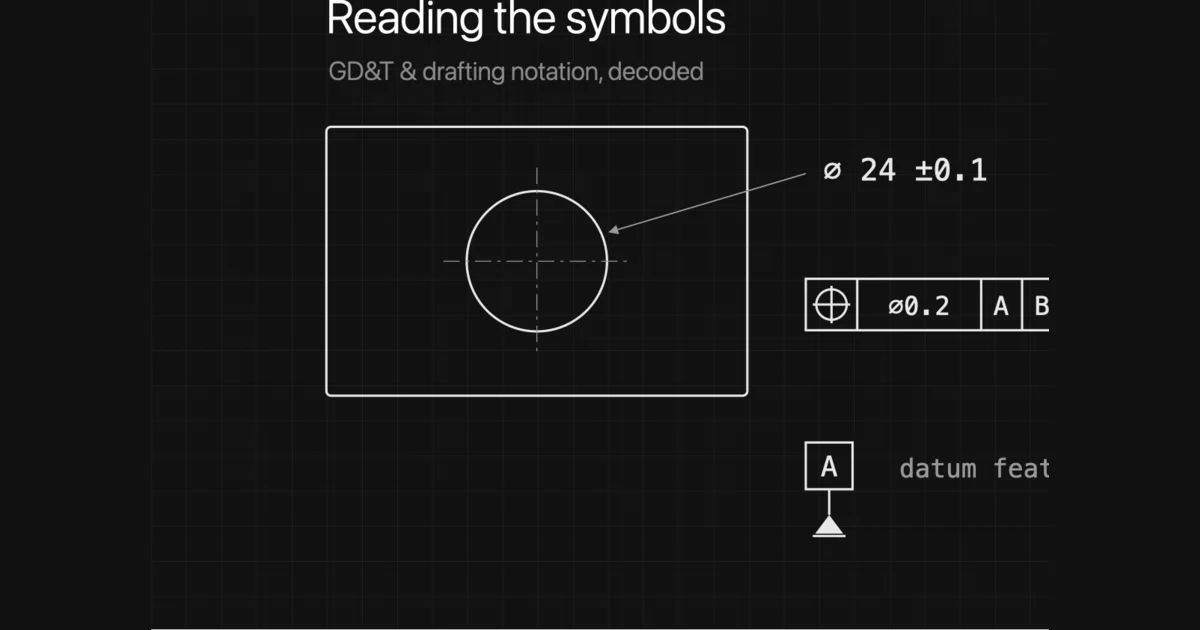
So a frame reading position | ⌀0.2 | A | B | Csays: the controlled feature's axis must lie within a 0.2 diameter cylindrical zone, located from datum A first, then B, then C. One line replaces a paragraph, and leaves nothing open to interpretation.
Datums: the reference frame everything is measured from
A geometric tolerance is meaningless without something to measure from. That something is a datum, a theoretically perfect plane, axis or point, derived from a real feature on the part called the datum feature. On the drawing a datum feature is marked with a capital letter in a box attached to a small filled or open triangle sitting on the surface or dimension line.
The letters themselves carry no ranking; A is not automatically more important than B. Priority comes from the order they appear in the feature control frame. The primary datum typically constrains the part first (three points of contact on a face), the secondary adds two more, the tertiary one more, until the part is fully located. Get the order wrong when you inspect and you measure the wrong thing.
Modifier and supplementary symbols
A feature control frame can carry more than a characteristic and a tolerance. A set of small circled letters and supplementary marks tune how the tolerance applies. These are the ones worth recognising, and they turn up as searches in their own right:
Modifier and supplementary symbols
| Symbol | Name | What it does |
|---|---|---|
Ⓜ | Maximum material condition (MMC) | Grants bonus tolerance as the feature departs from its most-material size. Common on holes and pins that only have to assemble. |
Ⓛ | Least material condition (LMC) | Applies the tolerance from the least-material size. Used to protect a minimum wall thickness or edge distance. |
Ⓟ | Projected tolerance zone | Projects the tolerance zone up out of the surface into the mating part, for fixed fasteners such as press-fit pins, dowels and studs. |
Ⓤ | Unequally disposed profile | Added in Y14.5-2018. Shifts a profile tolerance zone unevenly to one side of the true profile instead of centring it. |
Ⓕ | Free state | The requirement applies to a non-rigid part in its unclamped, free state, before assembly forces bend it into shape. |
Ⓣ | Tangent plane | Controls the tangent plane sitting on the surface's high points, rather than every local peak and dip beneath it. |
Ⓘ | Independency | Suspends the envelope rule for one feature, so form is not tied to size limits — an ISO principle you'll meet on drawings from Europe. |
A few supplementary marks are drawn on the leader rather than lettered in a box: a small circle at the elbow of a leader means all around (the profile applies to the whole outline), a double circle means all over, and ST between the arrowheads marks a statistical tolerance. The three material-condition modifiers are the ones that change the number of good parts you make, so they are worth understanding in full:
- MMC,
Ⓜ(maximum material condition). The state with the most material: the largest pin, the smallest hole. When MMC is invoked, a feature made away from MMC earns a bonus tolerance, extra position tolerance equal to how far it departed from MMC. This is common on holes and pins that just need to assemble. - LMC,
Ⓛ(least material condition). The opposite extreme: the smallest pin, the largest hole. Used when you need to guarantee a minimum wall thickness or edge distance. - RFS (regardless of feature size)is the default when no modifier appears. The tolerance stays fixed no matter the feature's size, with no bonus.
Surface finish, chamfers and the rest of the notation
Beyond size and geometry, a few more symbols carry requirements no dimension can:
- Surface finish. A check-like tick symbol with a value such as
Ra 3.2states the allowed roughness. A bar across the tick requires material removal; a circle in it forbids machining. Roughness is a whole language of its own — Ra vs Rz, N grades, lay — so we break it down in our guide to surface finish symbols. - Chamfer. Written as a distance and angle, eg
2 × 45°, or with aCprefix asC2for an equal 45° chamfer. - Taper and slope. Small symbols that look like a flattened triangle, stating a conical taper or a flat slope per unit length.
- Welding symbols. A whole sub-language built on a reference line and arrow, specifying weld type, size and side. Worth a guide of its own.
These often live in or near the notes rather than on a feature, and missing one is a classic way to make a part that is geometrically perfect and still wrong. A complete sheet pulls all of this together, which is the subject of what makes a drawing manufacturing-ready.
Putting the symbols to use
You do not have to absorb every symbol before a drawing becomes readable. A workable order:
- Get fluent with the dimensioning symbols in the first table. They cover the majority of callouts on the majority of parts.
- Learn to recognise the feature control frame and the datum symbolson sight, even before you know every characteristic. Knowing “this is a geometric requirement tied to datum A” is most of the battle.
- Add the 14 characteristics by family as you meet them, starting with position and the two profile controls.
- When you place them yourself, follow the rules of which dimensions matter and how to lay them out, covered in how to dimension a technical drawing.
Reading symbols and applying them well are different skills, and the second is where a lot of drawings quietly go wrong: a missing datum, a ± where a position callout belonged, a basic dimension treated as reference. If you are generating a drawing from a part or a photo rather than drafting it by hand, the same standards apply, the notation still has to be correct, and a person still needs to confirm the controls fit the part's function. That human check is the difference between a drawing that looks right and one a shop can actually cut from.
Frequently asked questions
What are the 14 GD&T symbols?
They are the geometric characteristics defined by ASME Y14.5: straightness, flatness, circularity and cylindricity (form); profile of a line and profile of a surface (profile); perpendicularity, angularity and parallelism (orientation); position, concentricity and symmetry (location); and circular runout and total runout (runout). Note that the 2018 revision of Y14.5 removed concentricity and symmetry, so newer drawings express those requirements with position or profile instead.
What does a circle with a line through it mean on a drawing?
That is the diameter symbol, written ⌀. A value like ⌀ 12 means the feature is 12 units across, not a 12 unit radius. Radius is written separately with a capital R, so R6 is a 6 unit radius.
How do you read a feature control frame?
Read it left to right in compartments. The first compartment holds the geometric characteristic symbol (such as position or flatness). The second holds the tolerance value, sometimes preceded by a diameter symbol and followed by a material condition modifier. The remaining compartments list the datum references in order of priority: primary, secondary, then tertiary.
What is the difference between a plus-minus tolerance and GD&T?
A plus-minus tolerance controls a single dimension between two limits. GD&T controls the geometry of a feature, such as how true a hole's position is relative to two reference surfaces, and it ties that control to datums. GD&T is more precise because it describes the function of the part rather than just the size of each dimension, and it usually allows more usable parts through with the same fit.
What does the box around a dimension mean?
A dimension drawn inside a rectangular box is a basic dimension. It is the theoretically exact location or size from which a geometric tolerance is measured. The allowable variation is not on the basic dimension itself; it lives in the feature control frame that references it.
Do I need to learn GD&T to read most drawings?
No. Views, the common dimensioning symbols and the notes carry most parts. GD&T is the layer you add when the geometric relationship between features drives whether the part works. Learn to recognise the feature control frame and the datum symbols first, then add the characteristics as you meet them.
What is the projected tolerance zone symbol?
A circled P, Ⓟ. It projects a position tolerance zone up out of the surface and into the part that mates with it, for a set height. You use it with fixed fasteners such as press-fit pins, dowels and studs, where what actually matters is the alignment of the fastener above the surface, not just at the face of the hole.
Is there a symbol for a critical dimension?
Not in ASME Y14.5 itself. There is no standard geometric symbol that means 'critical'. Critical or key characteristics are usually flagged with a company-specific mark, often a balloon or a small triangle or flag next to the dimension, defined in the drawing notes. The requirement it points to is still an ordinary tolerance or feature control frame; the flag only signals extra inspection attention.
What does a callout like 13 G5 or H7 mean on a drawing?
That is an ISO limits-and-fits tolerance code, not a GD&T symbol. The letter is the position of the tolerance band relative to the basic size (a capital letter is a hole, lowercase a shaft) and the number is the IT grade, or how tight the band is. So a bore marked H7 has a standard tolerance whose exact plus and minus values you read from an ISO fits table for that diameter. It is covered in how to read tolerances on a drawing.
Sources
- ASME Y14.5-2018: Dimensioning and Tolerancing
- Fictiv: GD&T 101, an Introduction to Geometric Dimensioning and Tolerancing
- GD&T Basics: The Symbols and Reference Charts
- ISO 1101: Geometrical product specifications (GPS), geometrical tolerancing
- ISO 128: Technical product documentation, general principles of presentation