A number on a drawing, say 20, is not a single size. No machine cuts to a perfect 20, so the real question every dimension silently answers is: how far off 20 is still acceptable? That answer is the tolerance, and it is written in four or five different styles depending on the feature. Learn to read all of them and a drawing stops hiding anything from you, including cryptic fit callouts like ⌀13 g5.
The short answer
Tolerances appear in three layers on a drawing. First, a general tolerance in the title block sets a default for every plain number. Second, individual ± or limit tolerances override that default on the dimensions that need it. Third, a fit callout such as ⌀13 H7/g6 handles the special case of two parts that must slide, locate or press together. Read tolerances on a drawing in that order — title block first — and nothing on the page is ambiguous.
This article is about dimensional tolerances, the ones that control size. The other half of the picture is geometric tolerancing, which controls form and position with symbols like flatness and true position; that lives in our GD&T symbols guide. The two systems work together, but they are read differently.
Why tolerances exist at all
Manufacturing is never exact. Cutting tools wear, metal expands with heat, fixtures flex, and two “identical” parts off the same machine differ by microns. A tolerance is the engineer's way of saying how much of that unavoidable variation the part can absorb and still do its job. Too loose and the parts rattle or do not fit; too tight and the price climbs while the yield drops.
That is the whole game: a tolerance is a negotiation between function and cost, written as a number. Reading one well means understanding not just the limits, but why someone chose them.
Plus-minus and limit dimensions
The most common form is the plus-minus tolerance, and it comes in two flavors:
- Bilateral — variation both ways, like
20 ±0.1. The feature is acceptable anywhere from19.9to20.1. The two limits do not have to be equal:20 +0.2/−0.1is still bilateral, just lopsided. - Unilateral — variation one way only, like
20 +0.2/−0. Acceptable from20.0to20.2, but never under 20. Used when a feature must never cross a hard line, such as a pin that must always enter a hole.
A limit dimension says the same thing by writing the two extremes directly instead of a nominal plus offsets. You will see it stacked:
20.10 over 19.90 means the feature must fall between those two numbers. It is identical to 20 ±0.1, just spelled out as the upper and lower limit. The top number is always the maximum, the bottom the minimum.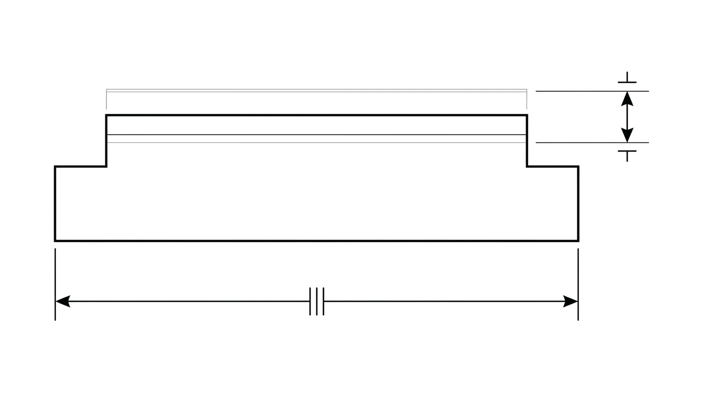
One trap worth naming: a value in a box, like a framed 20, is the opposite of a tolerance. That is a basic dimension, a theoretically exact value whose real tolerance is defined elsewhere, in a geometric feature control frame. Do not read a boxed number as “no tolerance”; read it as “tolerance lives in the GD&T.”
General tolerances: read the title block first
Most dimensions on a real drawing carry no individual tolerance, and that is deliberate. Writing ±0.1 on fifty non-critical dimensions would bury the page in noise. Instead the drawing states one blanket rule near the title block, and it governs every dimension that is not toleranced individually.
In the ISO world that rule is ISO 2768, written as something like ISO 2768-mK. The letters are tolerance classes:
ISO 2768-1 linear general tolerance classes (a selection)
| Class | Meaning | Example: a 30 mm dimension |
|---|---|---|
| f | Fine | ±0.15 mm |
| m | Medium | ±0.2 mm |
| c | Coarse | ±0.5 mm |
| v | Very coarse | ±0.8 mm |
The exact value depends on the size band (bigger dimensions get a wider band), so always check against the standard's table rather than memorizing one number. The point for a reader is simple: a plain number is not untoleranced. It inherits the title block's rule. Miss that line and you will misread most of the drawing.
.X = ±0.1, .XX = ±0.01, .XXX = ±0.005. Here the number of decimals you write is the tolerance you are asking for, which is why 20 and 20.00 are not the same instruction.Fits: what happens when two parts meet
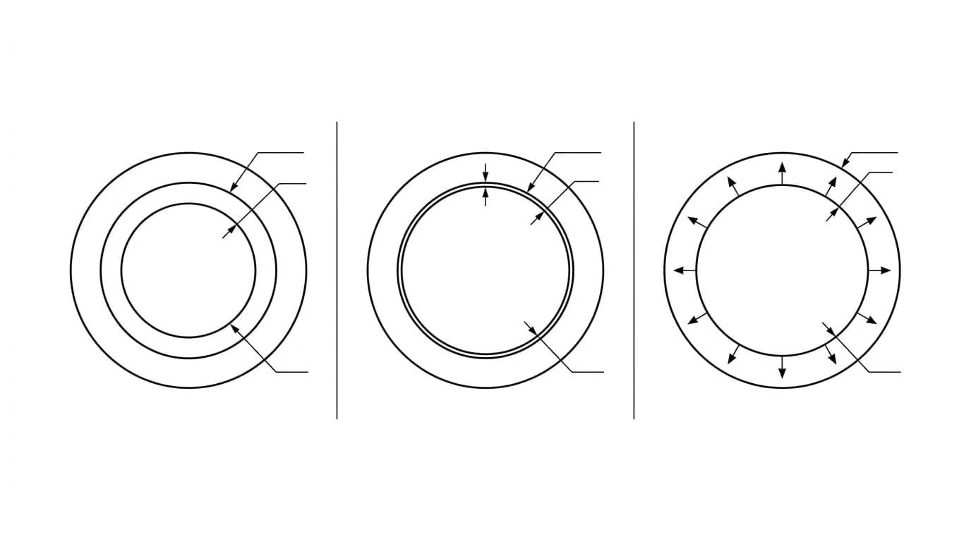
A single tolerance describes one feature. But the moment a shaft goes into a hole, a bearing onto a journal, or a pin into a bore, what matters is the relationship between the two sizes. That relationship is called a fit, and it falls into three families:
The three families of fit
| Fit type | What it does | Typical use |
|---|---|---|
| Clearance | The hole is always larger than the shaft — there is always a gap. | Sliding parts, bolts through holes, rotating shafts |
| Transition | The gap can be slightly positive or negative depending on where each part lands in its band. | Accurate location where parts are still assembled by hand |
| Interference | The shaft is always larger than the hole — the parts are pressed or shrunk together. | Press-fit bushings, bearing races, dowels meant to stay put |
You build a fit by pairing two tolerances, one on the hole and one on the shaft. Rather than spell out raw numbers every time, engineers use the ISO 286 shorthand, and that is where the letter-and number callouts come from.
Decoding a fit callout like ⌀13 H7/g6
An ISO fit callout looks intimidating and is actually three pieces of information stacked together. Take ⌀13 H7/g6:
- ⌀13 — the nominal (basic) diameter, 13 mm. Both the hole and the shaft share this nominal size.
- H7 — the hole. The letter is capital, so it is a hole.
Hplaces the tolerance band so the hole is never below nominal, and7is the IT grade that sets how wide the band is. - g6 — the shaft. The letter is lowercase, so it is a shaft.
gplaces the band just below nominal, and6is its IT grade.
So two letters carry the meaning. The case tells you hole or shaft. The letter itself tells you where the band sits relative to the nominal size — and therefore whether you get clearance, transition or interference. The number (the IT grade) tells you how wide the band is: lower is tighter and more expensive.
How the pieces of a fit callout map to meaning
| Symbol | Case / value | Tells you |
|---|---|---|
| H, G, F… | Uppercase | It is a hole |
| h, g, f, p… | Lowercase | It is a shaft |
| The letter | Position in the alphabet | Where the band sits → clearance vs interference |
| The number | IT grade (e.g. 5, 6, 7) | How wide the band is → how tight and costly |
H7/g6 is a precise sliding fit (small clearance, parts move freely), H7/k6 is a transition fit (snug location), and H7/p6 is a light press fit (forced together). The hole stays H7; the shaft letter does the work.What does “13 g5” mean on a drawing?
This is a search people type after staring at a confusing print, so let us answer it directly. 13 g5 is one half of a fit, the shaft half:
- 13 is the nominal diameter in millimetres.
- g is lowercase, so this is a shaft, and the
gposition sits just below nominal — a small, deliberate undersize that produces a slight clearance against a matching hole. - 5 is the IT grade, which is tight. A grade 5 band is only a few microns wide, the kind of precision you see on bearing journals and dowel shafts.
In plain terms: ⌀13 g5 is a precise shaft cut a hair under 13 mm, meant to drop into a close hole with a tiny, repeatable gap. Whenever you see a lone diameter followed by a lowercase letter and a single digit, read it the same way — shaft, position, grade.
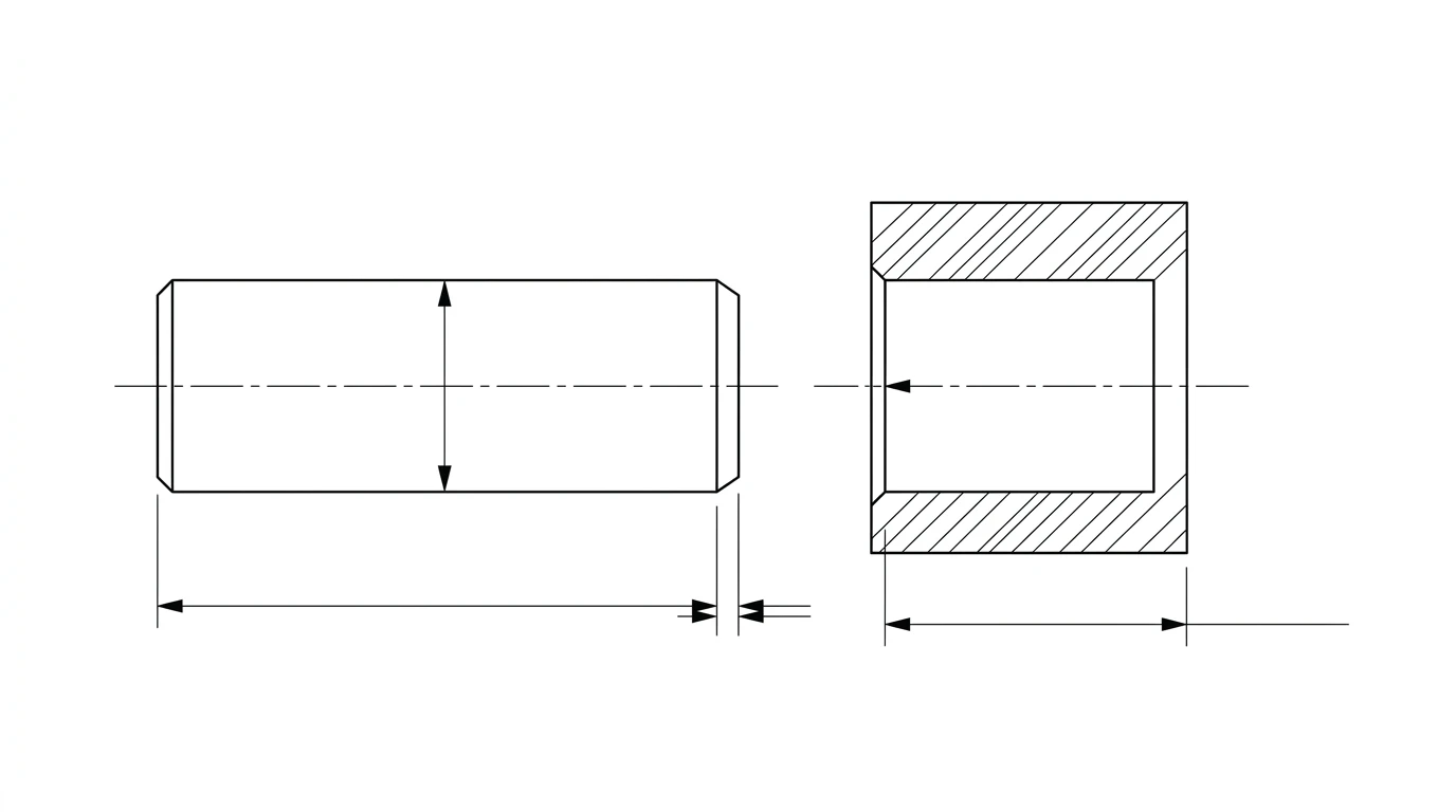
 Photo
Photo Drawing
How tight is tight enough?
Reading a tolerance is one skill; judging whether it is sane is another, and it is the one that saves money. Every step tighter multiplies cost, because it demands better machines, slower cuts, more inspection and more scrapped parts. A few rules of thumb a good reader carries:
- Only tighten what mates. The bore that takes a bearing needs a real fit; the bolt clearance hole three inches away does not. Most dimensions on a part should ride the general tolerance.
- Match the tolerance to the process. A laser or plasma cut profile holds roughly ±0.1–0.5 mm; milling and turning hold far tighter; grinding tighter still. Asking for a ground tolerance on a laser part is a quote-killer.
- Watch the stack-up. Tolerances add. Four features at ±0.1 in a chain can drift ±0.4 from end to end. If an assembly has to line up, dimension from a single datum rather than chaining, and see our dimensioning rules for how the layout itself controls this.
Adding tolerances to a photo-based drawing
If you are reverse engineering a part from a photo or a sketch, the geometry is only half the deliverable — a shop still needs the tolerances and fits to quote and machine it. This is the honest limit of any image-to-drawing tool: a photo can give you the shape and the proportions, but it cannot tell you that a bore was a H7 bearing seat or that a shaft was a g6 slip fit. That judgment comes from measuring the part and knowing what it does.
The workflow that respects this: generate the dimensioned drawing from your photo with TechDraw AI, anchor it to a real measurement so it is to scale (the reference-dimension trick does this), then you set the tolerance on each feature that mates — a ± on most, a fit callout on the few that matter. The tool builds the drawing; you supply the engineering intent. For when a part can ship with loose, general tolerances and no fit callouts at all, see do I need tolerances on a drawing.
Frequently asked questions
What does 13 g5 mean on a drawing?
It is an ISO limits-and-fits callout for a shaft. 13 is the nominal diameter in millimetres, g is the tolerance position (where the tolerance band sits relative to the nominal size — a lowercase letter means a shaft, and g sits just below nominal for a small clearance), and 5 is the IT grade (how wide the band is, with smaller numbers being tighter). So a ⌀13 g5 shaft is a precise shaft sized a few microns under 13 mm, designed to slide into a matching hole with a small, consistent clearance.
What does H7 mean on an engineering drawing?
H7 is an ISO tolerance for a hole. The capital letter H means it is a hole (lowercase is a shaft), H specifically places the tolerance band so the hole is never smaller than its nominal size, and 7 is the IT grade for the band width. H7 is the most common hole tolerance in general machining; it is the standard partner for many shaft fits such as H7/g6 (a precise sliding fit) or H7/p6 (a press fit).
What is the difference between a bilateral and a unilateral tolerance?
A bilateral tolerance allows variation in both directions, like 20 ±0.1, which permits 19.9 to 20.1. A unilateral tolerance allows it in one direction only, like 20 +0.2/−0, which permits 20.0 to 20.2 but never under 20. Unilateral tolerances are common when a feature must never cross a hard limit, such as a shaft that must always fit into a fixed hole.
What is ISO 2768 and where do I find it?
ISO 2768 is the general-tolerances standard. Instead of writing a tolerance on every single dimension, a drawing states one blanket rule in or near the title block, such as ISO 2768-mK, and it applies to every dimension that has no individual tolerance. The m is the linear tolerance class (fine, medium, coarse, very coarse) and the K is the geometric class. Always read the title block first, because it silently governs most of the numbers on the page.
What is the difference between a tolerance and a fit?
A tolerance is the allowed variation on a single dimension. A fit is the relationship between two mating dimensions — typically a shaft and a hole — and it is created by combining their two tolerances. A fit can be clearance (the parts always have a gap), interference (the parts are forced together), or transition (it could go either way within the band).
Does a drawing always need tolerances?
Yes. Every dimension carries a tolerance whether it is written or not, because nothing can be machined perfectly. If a dimension has no individual tolerance, the title block's general tolerance applies. A drawing with no tolerances anywhere is ambiguous, and a shop will either guess or stop to ask. See our note on whether you need tolerances on a drawing for when looser is fine.
Sources
- ISO 286-1: Geometrical product specifications (GPS) — ISO code system for tolerances on linear sizes
- ISO 2768-1: General tolerances for linear and angular dimensions without individual tolerance indications
- ASME Y14.5: Dimensioning and Tolerancing (the US standard)
- Engineering ToolBox: ISO tolerances for shafts and holes