




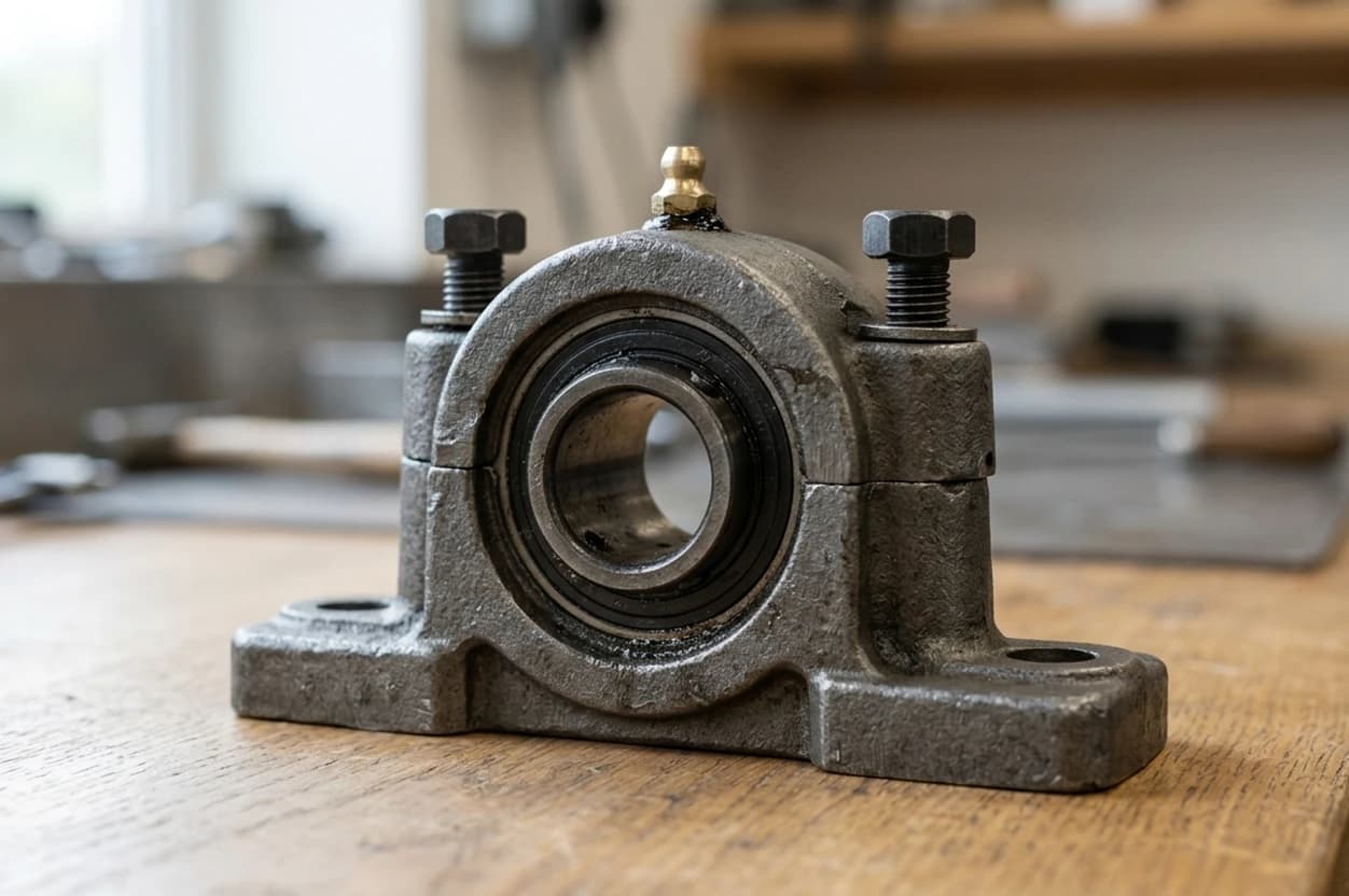
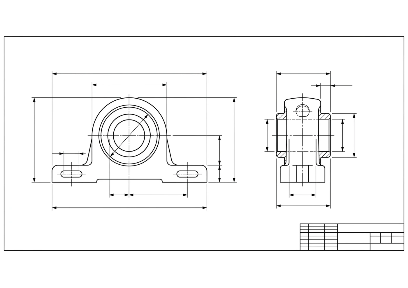
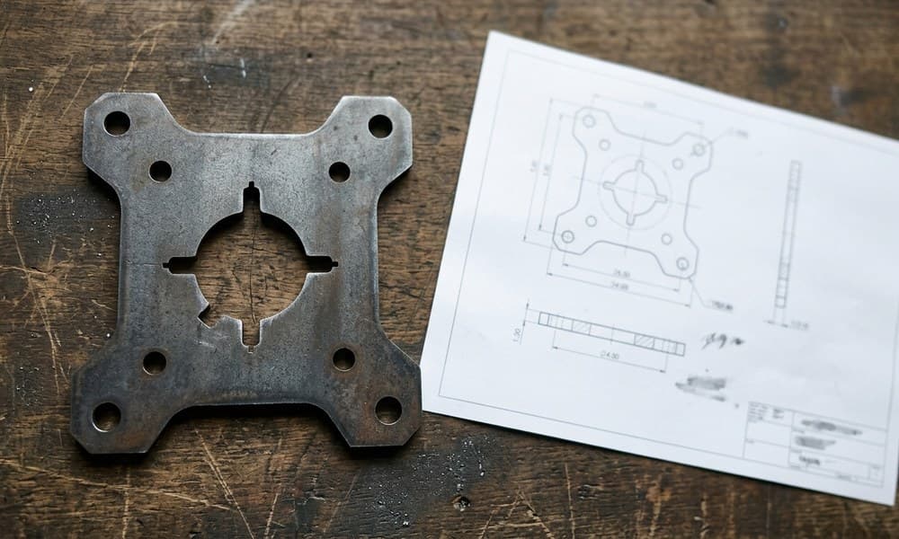
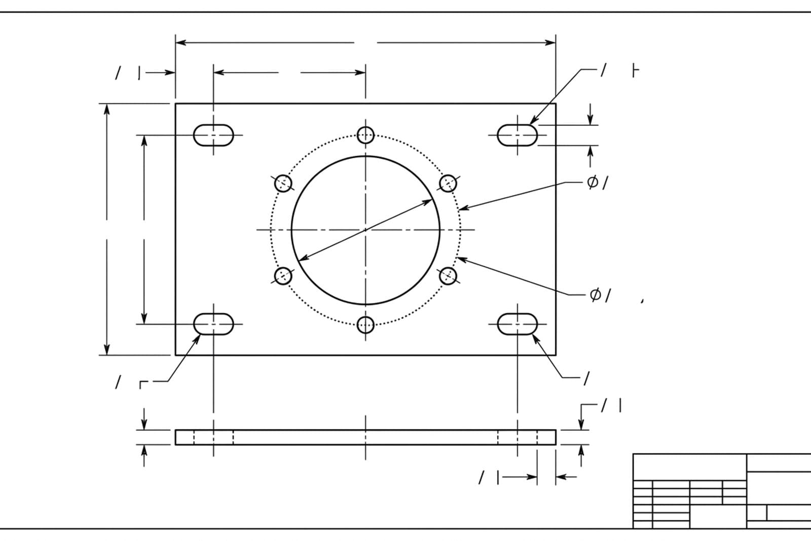
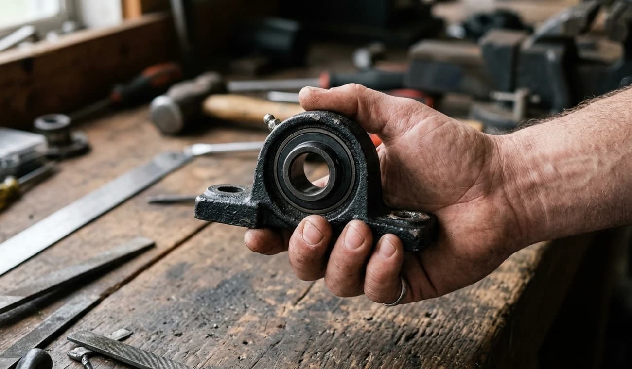
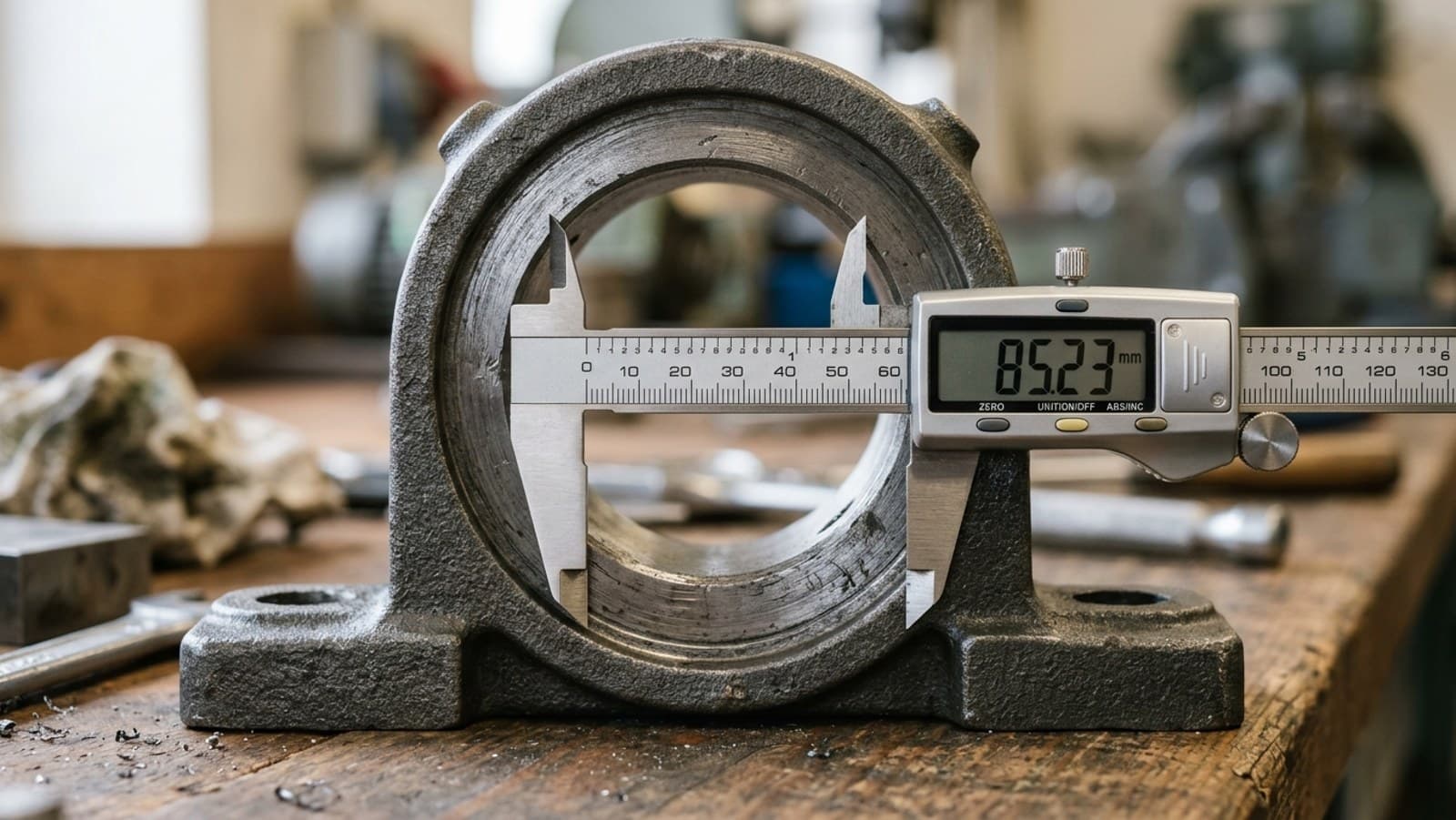
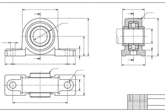
A machine goes down, the spare is in your hand and the drawing was never made. Photograph it, anchor one caliper measurement, and open the result in AutoCAD as a real DWG you can detail and issue.
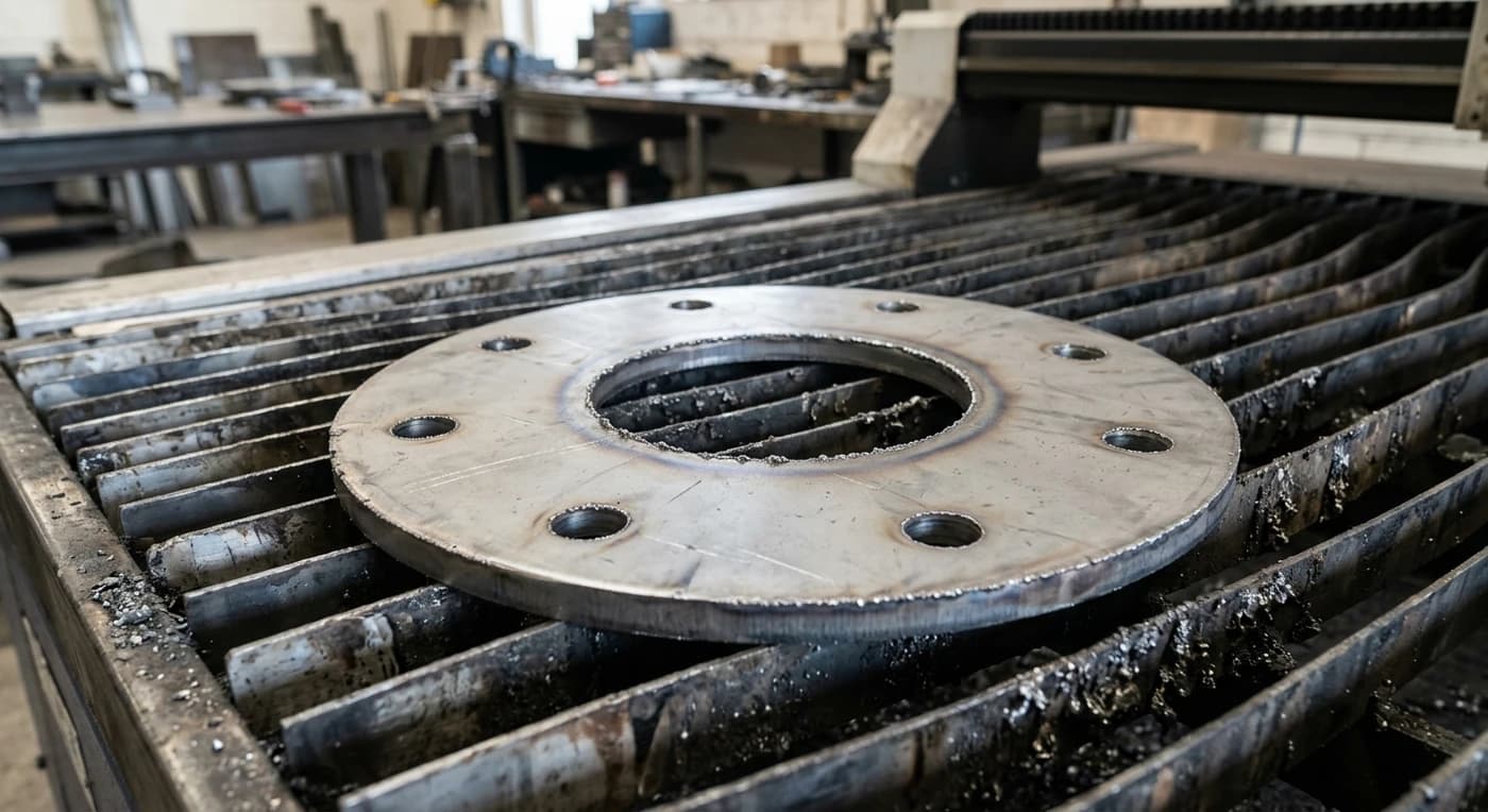
Gaskets, plates, brackets and laser profiles never need a 3D model. The DXF is already the production file. AutoCAD is where you check it, add the notes and plot it.
Photograph or scan the old sheet, get vector geometry back, then redraw and correct it in AutoCAD against your current standards instead of retracing every line over a raster underlay.
If your shop, your client and your archive all run on DWG, nothing changes. The file lands in the format everyone already uses, with your layers and title block applied on arrival.
Who does what
Division of labour, not redundancy. Each tool owns the half of the job it's actually good at.
| Step in the job | TechDraw AI | AutoCAD |
|---|---|---|
| Capture from a photo | ✓ | ✗ |
| Raster photo to vector geometry | ✓ | ✗ |
| Real measured dimensions | ✓ | ~ |
| Native DWG and DXF | ✓ | ✓ |
| Layers, blocks, xrefs | ✗ | ✓ |
| Layouts, title blocks, plotting | ~ | ✓ |
| Annotative scale and paper space | ✗ | ✓ |
| Best at | Photo to drawing | Drawing to issued sheet |
See it for yourself
Drop in a photo of a part. You'll get a dimensioned drawing and a DWG that opens straight in AutoCAD. No account needed to start.
The five-step handoff
This is the shortest handoff of any CAD tool we've written up, because DWG is AutoCAD's own format and there is nothing to translate. If the part is flat, like a gasket, a bracket or a laser plate, you can stop after step two and send the file to the machine.
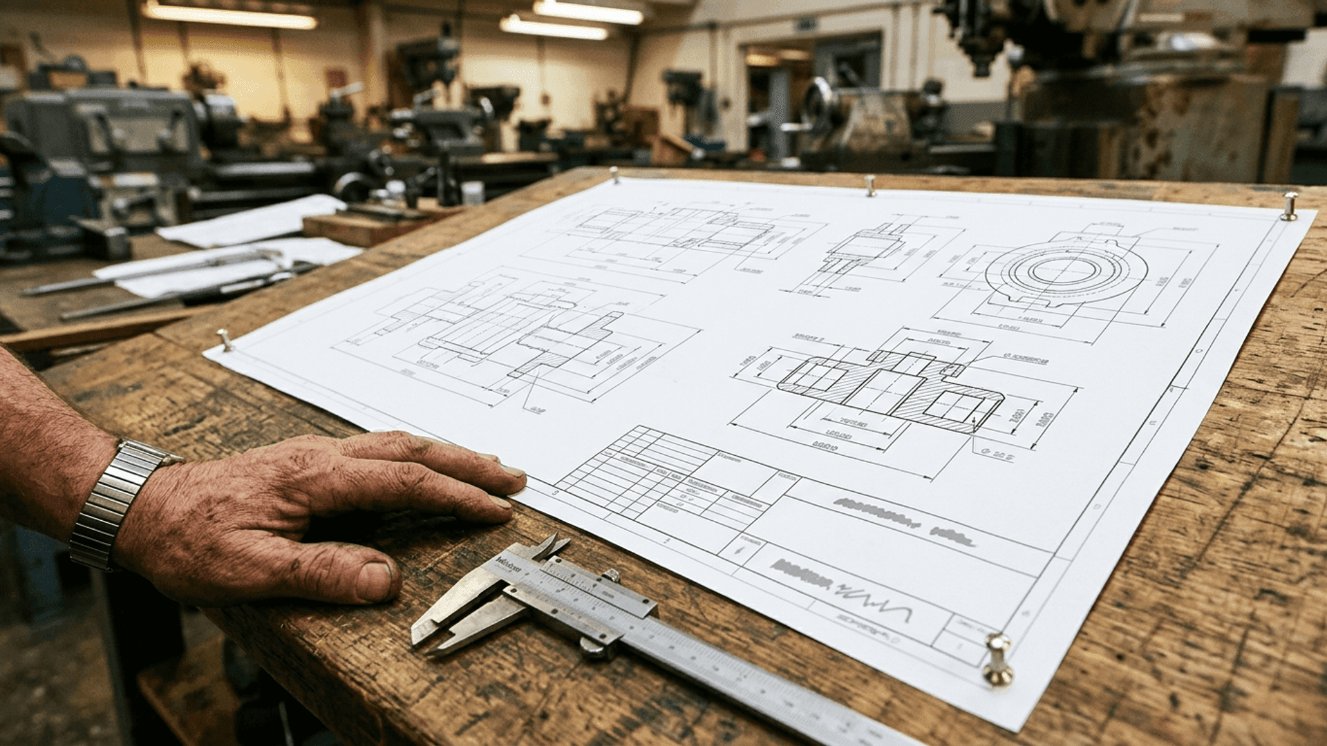
Export DWG and there is almost nothing to get wrong. The only three things worth checking are units, whether you inserted a block, and your annotative scale. All three are below.
Why AutoCAD can't do this on its own
This is worth being precise about, because “can AutoCAD convert an image to lines” is one of the most-asked questions in drafting and the honest answer has three parts. Two of AutoCAD's three raster commands do something useful. Neither of them does this.
- Attaches a JPG or PNG as a raster underlay
- Nothing is converted, it's a picture behind your lines
- You trace it by hand, entity by entity
- Accuracy is whatever your mouse managed that day
- Pulls real geometry out of a PDF, genuinely useful
- Only works if the PDF already holds vector geometry
- A scanned PDF stays a raster image on import
- So it never helps with a photo of a part
The short version:AutoCAD can trace a clean scan of a drawing that already exists. It cannot look at a physical object and work out what it measures. That gap is the whole reason this page exists, and it's also why the long-form guide to image to AutoCAD spends most of its time on the same three commands.
Three gotchas that waste ten minutes
None of these are hard. They're just the three that catch everyone the first time, and each has a one-command fix.
Cleanest habit: export the DWG for the geometry and keep the PDF of the same drawing open on a second monitor as your spec. You draft against clean lines and still have every number in front of you, which beats zooming around the model to read a dimension.
AutoCAD LT or full AutoCAD?
For this workflow it genuinely doesn't matter, and that is unusual enough to say plainly. LT is the version most drafting shops actually run, and the handoff here is a file, not a plugin or a script.
| Capability | AutoCAD LT | AutoCAD |
|---|---|---|
| Open the DWG natively | ||
| Open or INSERT the DXF | ||
| Edit, layer, annotate and plot | ||
| PDFIMPORT of vector PDFs | ||
| Raster Design vectorisation | ||
| Trace a photo of a part |
The partial mark is deliberate. Raster Design is included with a full AutoCAD subscription, but it vectorises bitonal scans, so it covers old drawings and not photographs. On the row that this whole page is about, both versions score the same: no.
Where this combo earns its keep
| Job | TechDraw AI | AutoCAD |
|---|---|---|
| Capture an undocumented part | ||
| Dimension it to real size | ||
| Clean up and correct the geometry | ||
| Apply layers, standards, title block | ||
| Plot, publish and issue the sheet |
Other CAD workflows
TechDraw AI hands a clean, dimensioned DXF to whatever you model in. Here's the same photo-to-3D handoff written up for other CAD tools.
Where the DXF comes from: a photo, one measurement, a dimensioned drawing.
All CAD workflows →The full hub: every TechDraw AI photo-to-DXF pairing in one place.
TechDraw AI + Fusion 360Insert the DXF into a Fusion sketch, then extrude or revolve it into a parametric model.
TechDraw AI + SolidWorksOpen the DXF with the DXF/DWG Import Wizard, then build a parametric SolidWorks model.
TechDraw AI + OnshapeImport the DXF, Use the curves in a Part Studio and model it in the browser.
TechDraw AI + Shapr3DImport the DXF onto a sketch plane, then Push/Pull or revolve it on iPad or Mac.
TechDraw AI + FreeCADImport the DXF in the Draft workbench, convert it to a sketch, then Pad or Revolve it — free.
TechDraw AI + InventorImport the DXF into a sketch, extrude or revolve it, then drive a production drawing and BOM.
TechDraw AI + SketchUpImport the DXF in SketchUp Pro, explode it to edges, then Push/Pull or Follow Me into a model.
TechDraw AI + TinkercadExport as SVG, import it into Tinkercad in the browser, and extrude it into a printable solid.
TechDraw AI + BlenderImport the DXF or SVG as a curve, convert to mesh, then Solidify or Screw it — free.
TechDraw AI + RhinoImport the DXF as exact curves, Join them, then ExtrudeCrv or Revolve into NURBS surfaces.
Start at the part, end at a DWG
Generate the dimensioned drawing in minutes, then open it in AutoCAD. No raster underlay, no tracing, no redrawing. Free to start, no account needed.
Frequently asked questions
Can AutoCAD convert an image to lines?
Not on its own, and this is the thing most people get wrong. IMAGEATTACH puts a JPG or PNG into your drawing as a raster underlay, which you then trace by hand, line by line. The Raster Design toolset does have real vectorisation tools, but they only work on bitonal (pure black and white) raster images such as scanned line drawings, and they are not available in AutoCAD LT. Pointing them at a photograph of a physical part does not work, because a photo has shading, shadows and a background rather than clean black lines on white. TechDraw AI is built for exactly that case: it reads the photo and gives you back dimensioned vector geometry as a DWG or DXF.
How do I convert a JPG to AutoCAD?
Upload the JPG to TechDraw AI, anchor one real measurement so the geometry comes out at true size, then export the result as DWG or DXF and open it in AutoCAD. That is the whole route. The alternative inside AutoCAD is IMAGEATTACH plus manual tracing, which produces lines that are only as accurate as your mouse and carries no real dimensions at all.
How do I import a TechDraw AI drawing into AutoCAD?
Export as DWG and simply open it, since DWG is AutoCAD's own format. If you want the geometry inside a drawing you already have open, use INSERT to bring it in as a block, then EXPLODE it if you need to edit the individual entities. DXF works exactly the same way through OPEN or INSERT.
Does this work in AutoCAD LT?
Yes. The handoff is a DWG or DXF file, and LT opens both natively. This matters because LT does not get the specialised toolsets, so Raster Design and its vectorisation tools are not available to you at all. If you are on LT, a photo of a part is otherwise something you can only trace by hand.
Why is my drawing the wrong size in AutoCAD?
A DXF carries no guaranteed unit, so a 50 mm part read as inches lands 25.4 times too big. Check INSUNITS and the drawing units before you blame the file. If it is already in and wrong, SCALE with the Reference option: pick two points you know the real distance between, type the true value, and everything comes to size at once. A clean export from TechDraw AI is already scaled to the reference measurement you gave it, so once the units agree it lands real-size.
Can I convert a scanned drawing to AutoCAD?
Yes, and it is one of the better uses for this. Photograph or scan the sheet and run it through TechDraw AI, and you get vector geometry instead of a picture. Note that AutoCAD's own PDFIMPORT only helps when the PDF already contains vector geometry; if the PDF is a scan, the raster stays a raster and you are back to tracing.
Should I export DWG or DXF?
For AutoCAD, DWG. It is the native format, it opens with one double-click, and nothing is translated on the way in. Export DXF when the file also has to go somewhere else, to a laser or waterjet, to a machine shop on different software, or into another CAD package. Both carry the same geometry.