
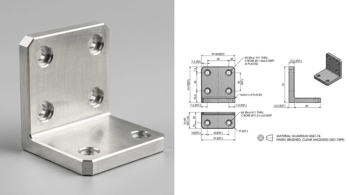
People who search “image to AutoCAD” usually know exactly where the file has to end up: open and editable inside AutoCAD, with real dimensions you can pull off it. Here is the catch. AutoCAD stores lines, arcs and dimensions as math, while a JPG or a photo stores coloured pixels and nothing else. None of it is geometry yet. So this was never really a file conversion. You are rebuilding the picture as linework, then giving that linework the one thing a photo never had, a real size. Do both and you get a drawing you can dimension and detail. Skip either one and you get a fuzzy outline sitting at the wrong scale.
Our articles are still written by humans!
Get human written articles in your Google feed.
Convert your image to AutoCAD DWG right here
Open the full converter pageDrop a file here. It never leaves your browser.
PNG, JPG, WebP, GIF, BMP, HEIC, TIFF, AVIF · any size · free · DWG or DXF · works best on clean line art, logos and high contrast shapes
The short answer
There are two ways to convert an image into an AutoCAD drawing that actually work, and no single “image to AutoCAD converter” covers both, because which one you need comes down to what your image really is. If it is already a drawing, meaning a scanned blueprint, a logo, a clean line graphic or a screenshot from a design tool, you vectorize it into lines and arcs, export DXF, and open that in AutoCAD. Close to mechanical. If it is a photo of a real object, tracing only hands you the outer silhouette, at whatever size and angle the camera caught. To get something you can build or quote from, you rebuild it with real dimensions and scale it to a known measurement. Either way, pixels do not turn into geometry on their own. A tracer, a person, or an AI has to draw the lines.
What AutoCAD can (and can't) do alone
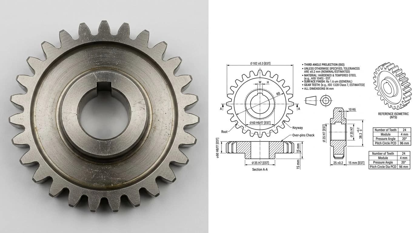
This is where a lot of people lose an afternoon, so it is worth saying plainly. Out of the box, AutoCAD does not have a button that turns a JPG into editable geometry. What it does have is a way to bring a raster image in as a background underlay, the ATTACH or IMAGEATTACH command, which you then trace over by hand with the normal drawing tools. The image is just a tracing template. The linework is yours to draw.
Automatic raster-to-vector, if you stay inside the Autodesk world, means one of two things. Either you add the AutoCAD Raster Design toolset, which vectorizes and cleans up scanned drawings, or you run a dedicated third-party converter and import the result. Both trace the visible shape well. Neither can invent the two things a picture never recorded: the real size and the dimensions. Worth keeping in mind, because no tool, Autodesk's own included, reads a size off pixels that never had one.
Drawing or photo? The fork
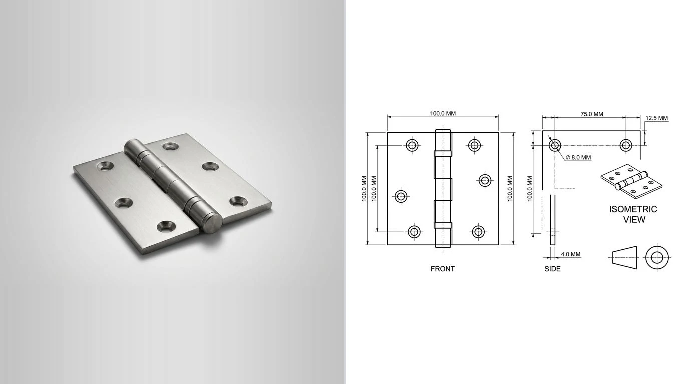
Before you touch a command, work out which kind of image you are holding. That one call decides whether the next hour is a quick trace or a full rebuild, and most bad results trace back to getting it wrong.
Three kinds of image, three different jobs in AutoCAD
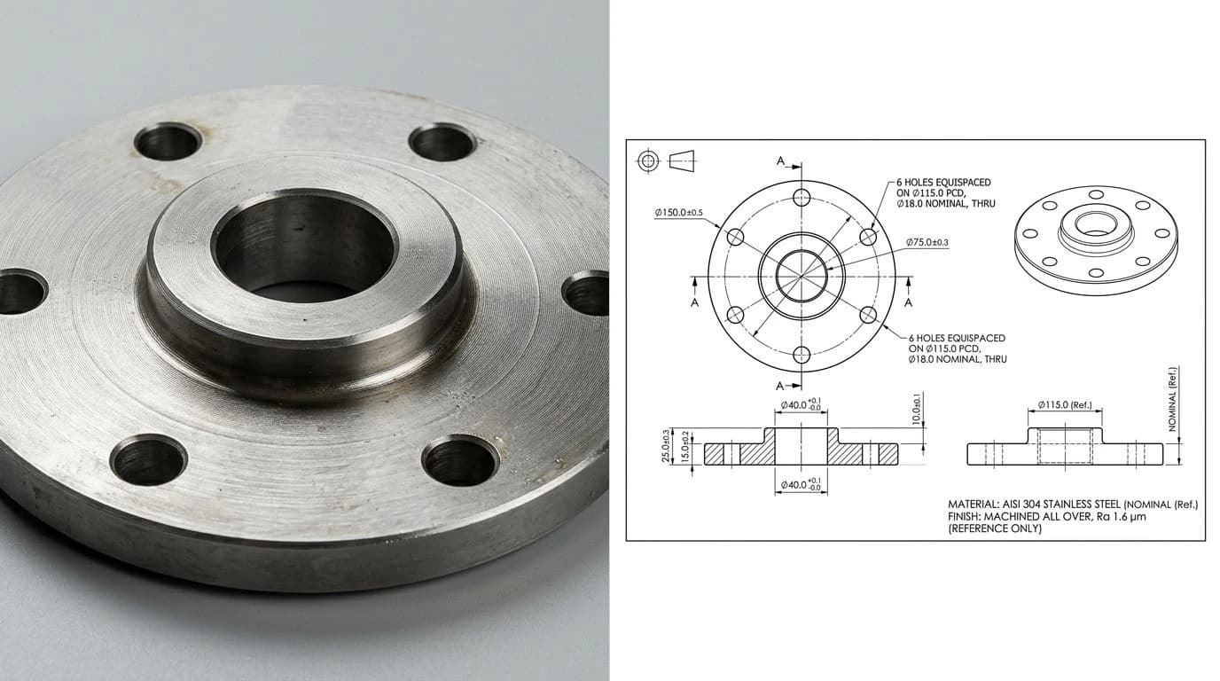
A scanned drawing or a logo is the easy case. The artwork already is the geometry, so the trace is faithful and the only real work is scale. A photo of a real part is the hard case, for a physical reason: a camera flattens a three-dimensional object onto a grid of pixels, so perspective, lens distortion and tilt all bend the outline, and there is no depth, no hidden edge and no dimension anywhere in the file. For the same decision across any CAD format rather than AutoCAD specifically, the pillar guide is image to CAD: turn a JPG into a drawing you can manufacture.
Three routes from image to AutoCAD
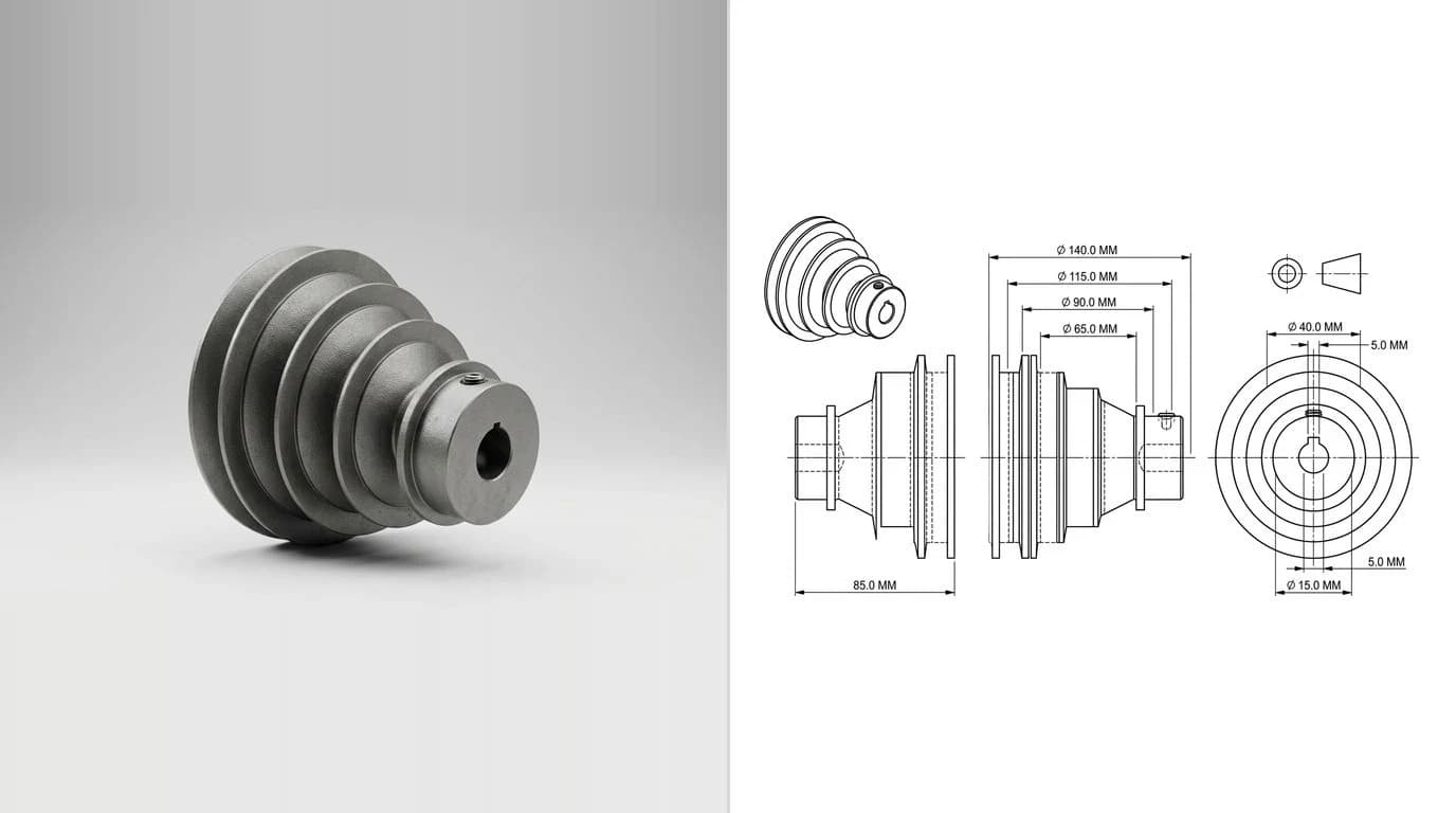
Depending on your image and how much editing you are willing to do, one of these three routes fits. They run from most manual to most automatic.
1. Attach and trace inside AutoCAD
Bring the image in with ATTACH, scale it to a known dimension, and trace over it on a fresh layer with LINE, PLINE and ARC. It is slow, but every line is yours and the result is genuinely clean. Best for simple parts, or any time you want full control over how the geometry gets built. Step by step below.
2. Vectorize to DXF, then open it
Run the image through a raster-to-vector tool, either Inkscape's Trace Bitmap for free or a dedicated converter, export DXF, and open that in AutoCAD. Quick for logos and clean line art. The catch is that the DXF shows up at a pixel-based scale, so you still rescale it once it is in. If the trace comes out rough, with doubled lines, jagged arcs or broken corners, that is an input problem, and why a traced image looks jagged and how to fix it walks through the cleanup. A side-by-side of the dedicated converters is in the best JPG to DXF converters.
3. Reconstruct a dimensioned drawing with AI
For a photo of a real part, neither tracing route gives you a drawing you can use, because both stop at the silhouette. An AI tool that rebuilds the part as a dimensioned technical drawing, from a single reference measurement, gives you DWG or DXF with real lengths, closed profiles and proper views. Which is what you were after in the first place. More on where it fits under tools.
Attaching and tracing a raster
Going the manual route? This is the order that works. Miss the scaling step and everything after it comes out wrong, so do it first.
- Attach the image. Type
ATTACH(orIMAGEATTACH), choose your JPG, PNG or TIFF, and place it in the drawing. Uncheck “Specify on-screen” scale if you want to fix the size properly in the next step. - Scale it to a known dimension. Run
SCALE, select the image, pick a base point, typeRfor Reference, click the two ends of a feature whose true length you know, and enter that real length. The image now sits at 1:1 with the world. - Lock the image on its own layer. Put it on a dedicated layer, fade it back with
IMAGEADJUST, and lock the layer so you don't select it by accident while drawing. - Trace on a new layer. Draw the geometry with
LINE,PLINE,ARCandCIRCLE, snapping to the visible edges. Use object snaps to keep corners crisp and profiles closed. - Detach or freeze the image. Once the linework is done, freeze the image layer or
DETACHthe raster. Add dimensions, and you have a real AutoCAD drawing.
Scan to AutoCAD: scanned drawings and PDFs
A scan is its own case, and it is worth treating separately because the input quality decides everything. A scanned blueprint is already a drawing, so the goal is a faithful trace, not a rebuild. Three things make or break it. Resolution: scan at 300 dpi or better, because a vectorizer cannot recover a line the scanner blurred away. Skew: a page scanned at a slight angle bakes that angle into every line, so deskew before you trace, or your “horizontal” lines all sit at 0.4 degrees. Speckle: dust and fold marks get traced as geometry, and you delete them one by one later. Raster Design and Scan2CAD both have cleanup passes for exactly this.
If the scan arrived as a PDF, check what is inside it first. A PDF made by a CAD program carries real vector geometry, and AutoCAD's PDFIMPORT command pulls that straight in as editable lines, no tracing at all. A PDF made by a scanner is just a photograph of paper in a different wrapper, so PDFIMPORT brings it in as an image and you are back to the attach-and-trace route above. How to tell the two apart, and what to do with each, is in PDF to DXF. The wider scanned-drawing workflow, including rebuilding a part when the original drawing is lost for good, is in scan to CAD: digitize a paper drawing.
The scale trap in AutoCAD
This is where more image-to-AutoCAD jobs fall apart than anywhere else, and it is baked right into the formats. A raster image is measured in pixels. An AutoCAD drawing is measured in real units, millimetres or inches. Nothing in a JPG or PNG says how many millimetres a pixel is worth, so whatever brings it in has to guess, and the guess is almost never your part's real size. It looks right on screen and comes out wrong at the machine.
The fix never changes, and it is not optional. Find one dimension you know for certain, printed on the drawing or measured off the real part with calipers, and scale the whole thing so that feature matches the known number. Get one length right and every other length follows, because the proportions were already correct. That exact failure, and how to catch it before it becomes scrap, is in fixing a drawing that imports at the wrong size, and the reference-measurement idea in depth is in how to get dimensions from a photo.
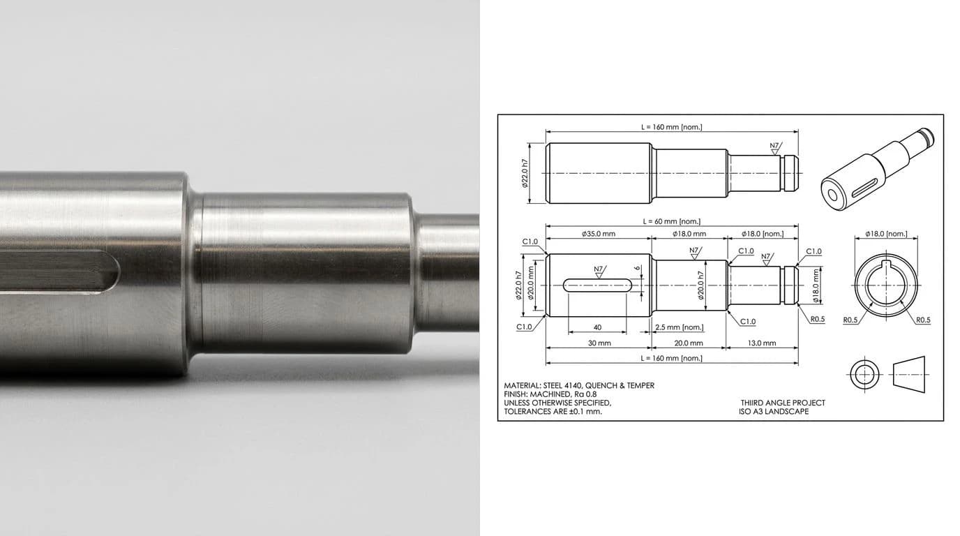
Working the other way round, from a real part in your hand to a drawing, is the same problem in reverse, and how to reverse-engineer a part from a photo walks through it. Once the geometry is scaled, dimensioning it cleanly is its own skill, covered in how to dimension a technical drawing.
DWG or DXF for AutoCAD?
When a tool exports the file for you, you usually get to pick the format, and for AutoCAD the choice is easy. DWG is AutoCAD's native format, Autodesk's own binary drawing format, so it opens with no translation and keeps the most fidelity when a tool can write it. DXF is the neutral exchange format almost every other program can produce, and AutoCAD opens it just as cleanly and turns it into DWG the moment you save. In practice, take DWG when it is offered, take DXF when it is not, and don't lose sleep over the difference for 2D linework.
The full comparison, including when a supplier specifically asks for one or the other, is in DWG vs DXF. If your goal is specifically the DWG file rather than the AutoCAD workflow around it, image to DWG: convert a picture to a DWG file approaches the same conversion from the format's side, including the version trap when a converted DWG refuses to open. The wider map of which format each machine and shop actually wants is in CAD file formats for manufacturing. If the file is headed to a laser or CNC shop instead of back into AutoCAD, our image to DXF converter covers the cutter side. For one specific source there are pages for a JPG and for a photo.
Tools that get an image into AutoCAD
Image to AutoCAD, by tool
For a scanned drawing or a logo, the tracers are genuinely enough. There is no accuracy to buy by paying, only convenience, and even free Inkscape exports a DXF AutoCAD opens directly. Where all of them stop is the photo-of-a-real-part case, because none can supply the one thing a picture lacks: a real size and the dimensions that come with it.
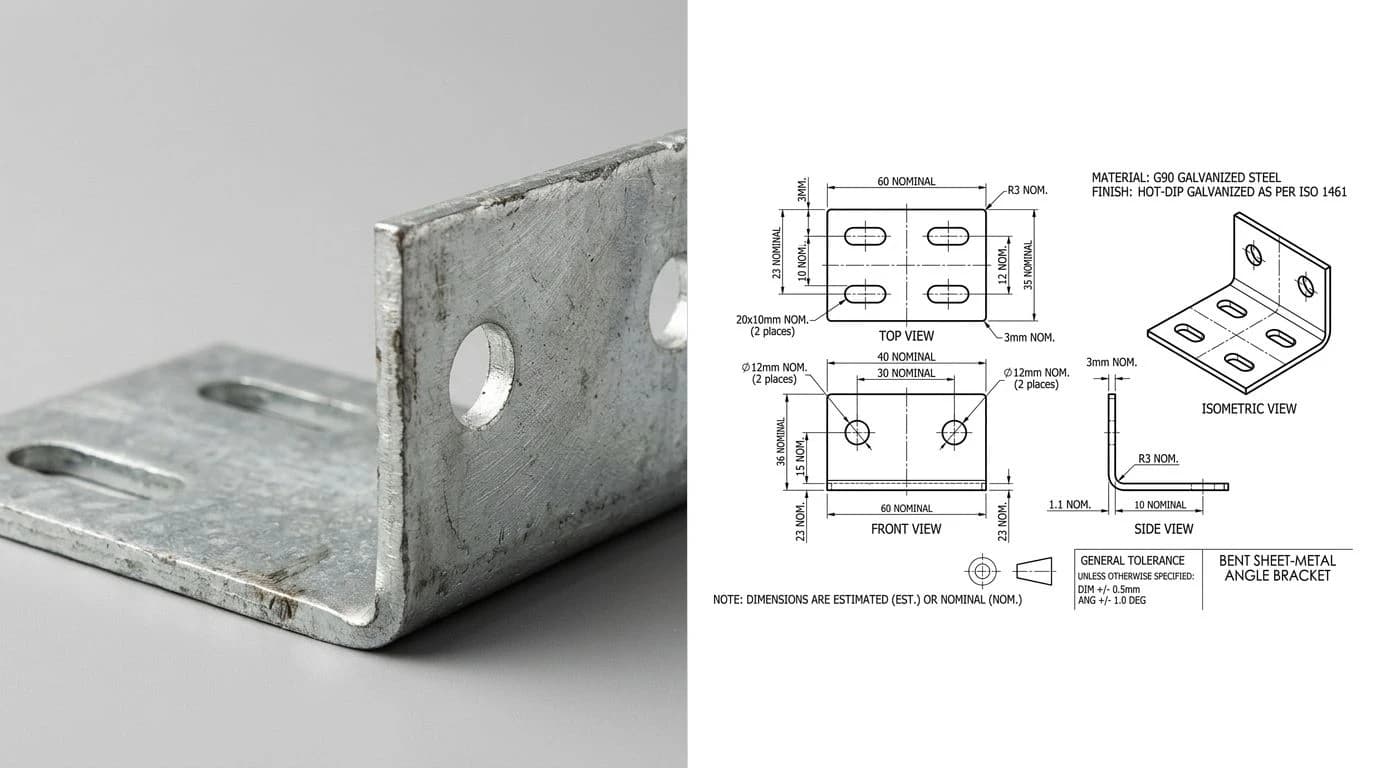
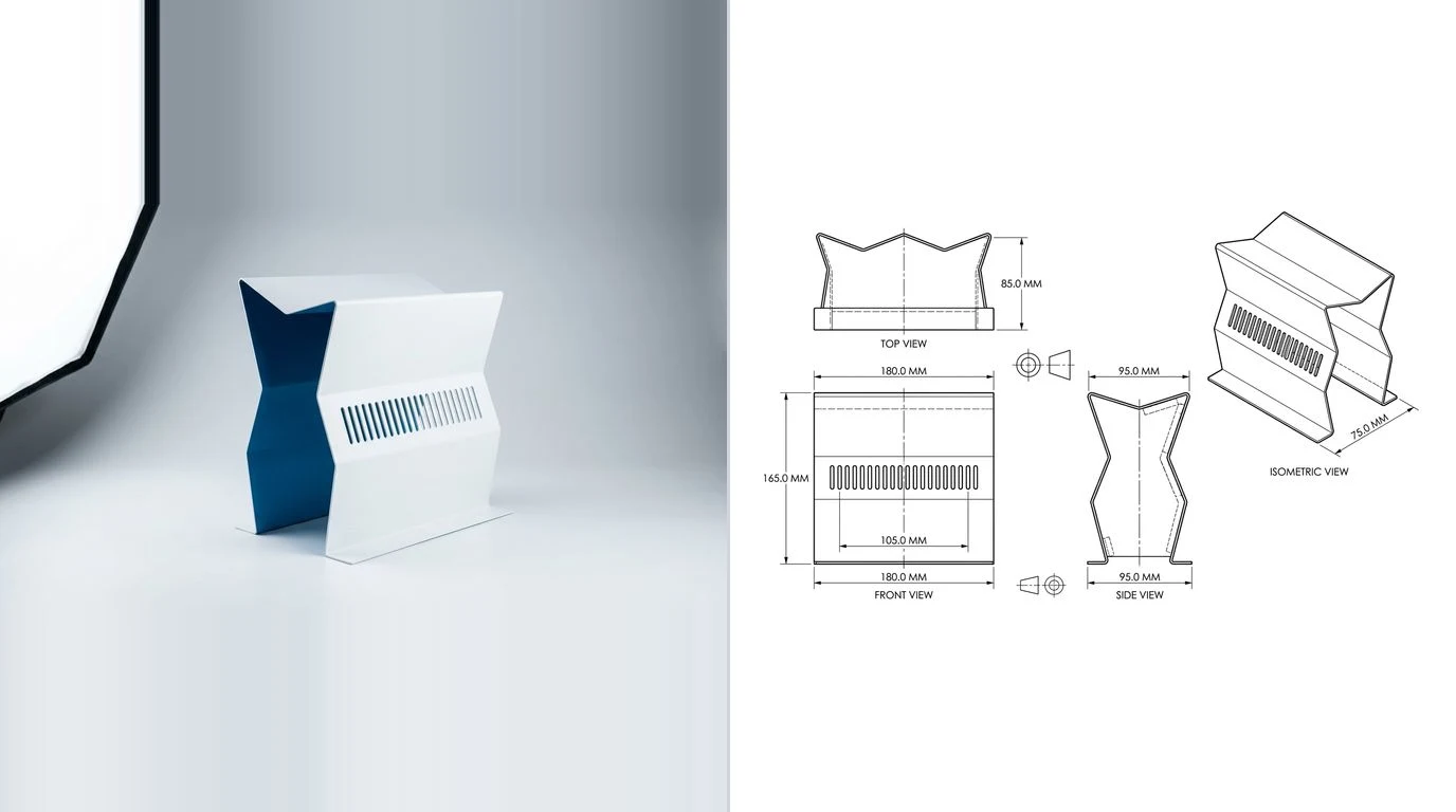
That gap is what our AI technical drawing generator is built for. You upload the image, type in one real measurement, and it rebuilds a dimensioned technical drawing: orthographic views, closed profiles, every length tied to your reference instead of to pixels. Then it exports a clean DWG, DXF, SVG or PDF you open straight in AutoCAD. It stays honest about the ceiling too. You get a measurable 2D drawing you can edit and quote, not a 3D solid conjured out of one photo. Starting from a rough sketch instead of a photo? The sketch to CNC-ready DXF workflow covers that, PDF to DXF covers the case where the image arrived wrapped in a PDF, and, for the folded parts above, turning a photo into sheet-metal drawings goes deeper on bends, flats and flange lengths. If you just want the commands, the TechDraw AI and AutoCAD workflow page lays out the whole handoff, export, OPEN, EXPLODE, units, plot, on one screen.
Pre-flight checklist
- Did you pick trace or rebuild on purpose? A drawing gets traced; a photo of a real part gets rebuilt. Guess wrong here and every step after it is wasted.
- Did you start from the cleanest image you have? A PNG, a native export or a high-resolution scan beats a compressed JPG.
- Did you scale to one known dimension? Verified against a print or a measured feature with
SCALEand itsReferenceoption, not assumed. This is the single most common way the job turns into scrap. - Is the linework actually clean? Closed profiles, and no duplicate or stray lines left over from the trace.
- Did you save the right format? DWG for AutoCAD, DXF (often R12) if the file is moving on to a shop or a cutter.
Clear that list and you have a real, editable AutoCAD drawing instead of a picture pinned behind glass. If the part is headed for a quote rather than your own screen, what a shop needs beyond the linework is in from photo to a manufacturing drawing.
Watch: Insert and scale an image for tracing
Brandon of CAD Intentions covers route 1 from this page: inserting an image into AutoCAD, scaling it, and then tracing or digitizing it with the standard drawing commands. That is the attach, scale and trace sequence in the step list above, and the scaling step is the one that decides whether anything you trace comes out the right size. It stops at the trace, so for a photo of a real part you still need the dimensions a trace cannot give you.
Frequently asked questions
Can AutoCAD convert an image to a drawing automatically?
Not on its own. Stock AutoCAD can attach a raster image as an underlay for you to trace over by hand, but it has no built-in button that turns a JPG into editable linework. Automatic raster-to-vector needs Autodesk's Raster Design add-on or a third-party tool like Scan2CAD, and even then it only traces the visible shape. It never recovers the real-world scale or the dimensions, because a picture never contained them.
How do I insert an image into AutoCAD to trace it?
Use the ATTACH command (or IMAGEATTACH) and pick your JPG, PNG or TIFF. Place it, then scale it to a known dimension with the SCALE command's Reference option so one feature matches its true size. Put your new geometry on a separate layer, trace the edges with LINE, PLINE and ARC, then detach or freeze the image layer when you are done.
Can I convert a JPG to AutoCAD?
Yes, but a JPG is the hardest input to work with. Compression halos around every edge get traced as fake geometry, so the linework comes out fuzzy. Convert a high-quality version, or a PNG or native export if you can get one. Free tools like Inkscape vectorize the JPG and export DXF, which AutoCAD opens directly, though you still have to set the real scale afterwards.
Can I convert a photo of a real part into an AutoCAD drawing?
You can, but tracing a photo only gives you a silhouette at whatever angle and size the photo was taken. There are no inner features, no dimensions, and any perspective tilt bakes into the shape. For a part you actually need to make, rebuild it as a dimensioned drawing from a reference measurement, then open that DWG or DXF in AutoCAD instead of tracing the pixels.
Is DWG or DXF better for opening in AutoCAD?
DWG is AutoCAD's own native format, so it is the cleanest choice when a tool can write it. DXF is the neutral exchange format almost every other program can export; AutoCAD opens it just as well and converts it to DWG on save. If you are handing the file to a shop instead, DXF (often the older R12 version) is the safer bet for compatibility.
How do I convert an image to lines in AutoCAD?
Attach the image as an underlay, then draw the lines yourself over it with LINE, PLINE, ARC and CIRCLE on a fresh layer; stock AutoCAD has no command that converts the pixels to lines for you. If you want the trace automated, run the image through a raster-to-vector tool or the Raster Design toolset first and import the resulting DXF, then clean up the linework it produced.
Can I convert a scanned drawing to AutoCAD?
Yes, and a scan is the best-case input because the artwork is already a drawing. Scan at 300 dpi or better, deskew the page, then either trace it in AutoCAD over the attached image or vectorize it with Raster Design or Scan2CAD and import the DXF. If the scan lives inside a PDF that originally came from CAD software, PDFIMPORT recovers the real vector geometry directly, with no tracing at all. One thing to check in whatever tool you use: a naive tracer follows both edges of every inked line and hands you two parallel lines per stroke, so a drawn line 0.5 mm thick arrives as a long thin rectangle. What you want is the centre line of the stroke, one line where the drafter drew one line, or you will spend longer deleting duplicates than you saved.
How do I scale an inserted image to the right size in AutoCAD?
Run SCALE, select the image, pick a base point, then type R for Reference. Click the two ends of a feature whose real length you know, and type that true length. AutoCAD resizes the whole image so that one dimension is correct, and because the proportions were already right, every other measurement follows.