
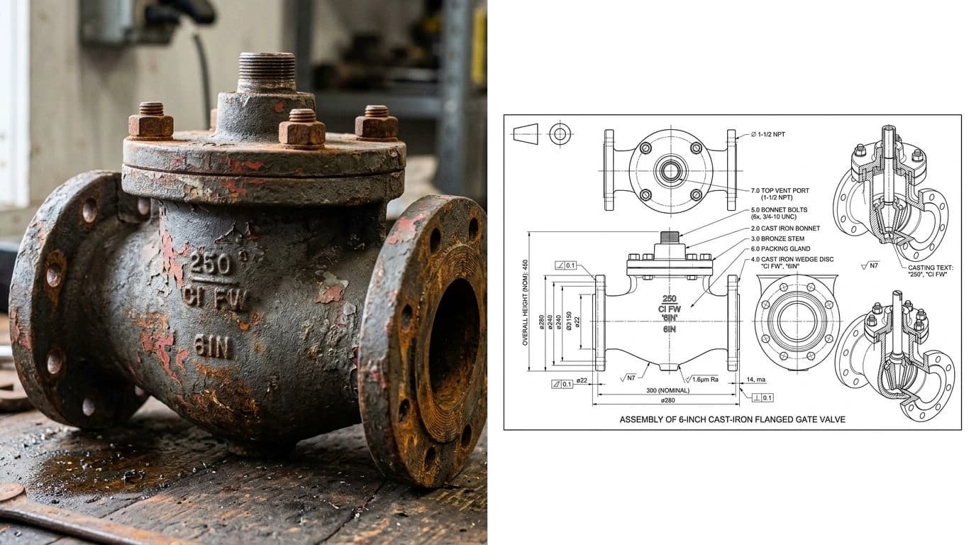
Searching “scan to CAD” usually means one of two situations. Either you have a drawing on paper, a print, an old blueprint, a scanned PDF, and you need it back as an editable file. Or the drawing is gone entirely and all you have left is the part itself. These are not the same job, and the reason they feel like one is that both start with something flat and end at a DWG. Here is the honest split. A clean scan of a drawing can be traced into geometry. A part with no drawing has to be rebuilt from scratch. Get that call right first and the rest is straightforward. Get it wrong and you waste an afternoon tracing something that was never going to work.
Our articles are still written by humans!
Get human written articles in your Google feed.
The short answer
Yes, you can get a scan into CAD, but the right method depends on what you are actually holding. If it is a clean scan or a scanned PDF of a line drawing, run it through a raster-to-vector tracer, clean up the linework, and export DWG or DXF. If the scan is faded, marked up or skewed, clean it first or the trace comes back as a mess. And if there is no drawing at all, only the part, no tracer can help, because there is nothing on a page to trace. You rebuild the drawing from a photo of the real object. Below, each route, and how to tell which one you need.
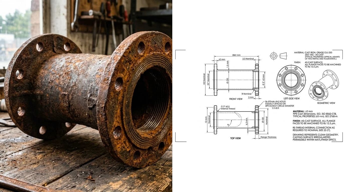
Clean scan, faded blueprint, or no drawing at all?
Three different inputs hide behind the same search, and each one needs a different tool. Sorting yours before you start is the single most useful thing on this page.
Three inputs behind scan to CAD, three different jobs
The first case is the easy one, and it is genuinely close to a solved problem. The artwork on the page already is geometry, so a tracer follows it faithfully. The third case is where most legacy work actually lands: a bracket, a valve or a casting that has outlived its paperwork. There is nothing to trace, so the job is reverse engineering, covered in depth in how to reverse-engineer a part from a photo. For the wider decision across every CAD format, the pillar guide is image to CAD: turn a picture into a drawing you can manufacture.
Three ways to get a scan into CAD
Whichever input you have, one of these three routes fits. They run from most automatic to most hands-on, and picking the wrong one is where the time goes.
- Trace the scan to vector. Run a raster-to-vector tool over a clean scan, get DXF linework, and open it in CAD. Fast for clean line drawings, and the free option, Inkscape, is genuinely fine for simple sheets.
- Attach and trace by hand. Bring the scan into AutoCAD as an underlay with
ATTACH, scale it to a known length, and draw over it. Slow, but every line is yours and the result is clean. - Rebuild from the part. When the drawing is lost or unreadable, photograph the real object and let an AI tool reconstruct a dimensioned drawing from one reference measurement. The only route that adds real dimensions rather than copying an outline.
If your scan arrived as a PDF, sort out whether it is vector or raster first, because that changes everything, and PDF to DXF walks through it. Once the geometry is in and it opens at the wrong size, which happens more than anyone admits, fixing a drawing that comes in at the wrong size is the fix.
Where a raster tracer like Scan2CAD fits
For a clean scanned drawing, a dedicated raster-to-vector tool is the obvious pick, and Scan2CAD is the name most people search for. It traces black linework into vectors, does some OCR on text, and exports DWG or DXF. Autodesk's own Raster Design toolset does the same inside AutoCAD, and free Inkscape traces a bitmap to DXF for nothing. For simple sheets, the free route is often all you need, and the paid tools buy convenience and batch handling, not accuracy.
Be clear-eyed about what any tracer can and cannot do. It reproduces the shape on the page well. It does not recover the real-world scale, because a scan never stored one, and it faithfully copies every defect on the paper. If the trace comes back with doubled lines and jagged arcs, that is an input problem, and why a traced image looks jagged and how to fix it covers the cleanup. A side-by-side of the dedicated converters sits in the best JPG to DXF converters.
When the drawing is gone: rebuild from the part
This is the case tracers cannot touch, and it is more common than the clean-scan case in real shops. A part has outlived its drawing. The paperwork was lost in a move, the supplier folded, or the drawing was never made because someone built the thing on a lathe forty years ago. There is no page to scan. What you have is the object.
Here the input is not a scan at all, it is a photo of the real part, and the job is to reconstruct the drawing from it. An AI tool that does this takes your photo plus one real measurement and rebuilds orthographic views with dimensions, closed profiles and proper projection, then exports DWG, DXF, SVG or PDF. It stays honest about the ceiling too. You get a measurable 2D drawing you can edit and quote, not a 3D solid conjured out of one photo. The reference-measurement idea, which is what makes it accurate, is in how to get dimensions from a photo, and the photo-first sibling of this guide is photo to CAD: turn a picture of a part into DWG or DXF.
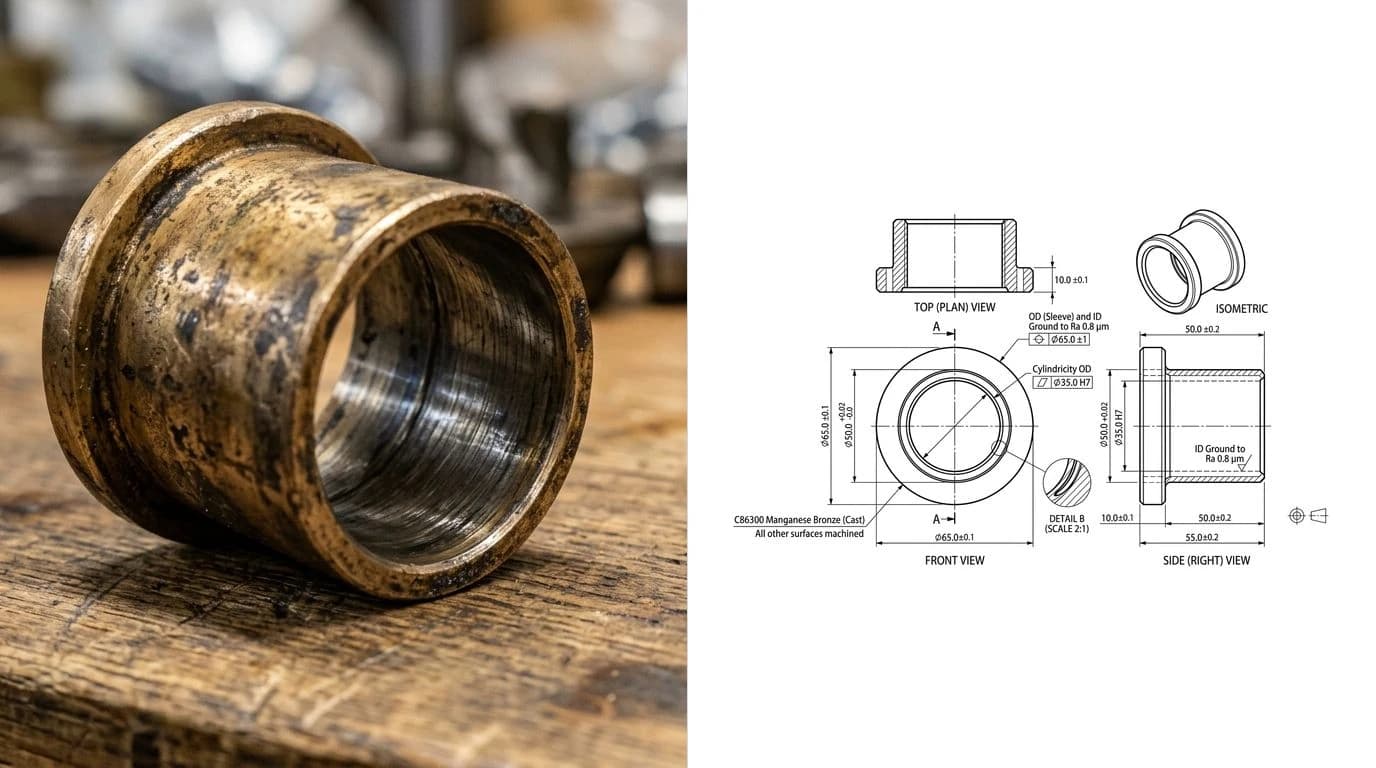
What survives the conversion, and what does not
It helps to be blunt about what actually carries over, because the gap between “looks right” and “is right” is where scrap comes from.
- Shape and proportion survive well from a square, undistorted scan or a straight-on photo. The outline you see is the outline you get.
- Scale does not survive at all. No scan or photo stores units, so every drawing lands at some arbitrary size until you anchor one known dimension. This is not optional.
- Text and dimensions are hit or miss. OCR on a clean sheet reads printed numbers reasonably well, but faded or handwritten values need checking by eye. Never trust a machine-read dimension blindly.
- Hidden detail is simply gone. A scan only holds what was drawn, and a photo only holds what the camera saw. Internal features that were never on the page, or never visible, do not appear.
The one habit that separates a usable file from a nice picture is verifying a single length against a source you trust, a printed dimension or a caliper on the real part. Everything else flows from that one number being right.
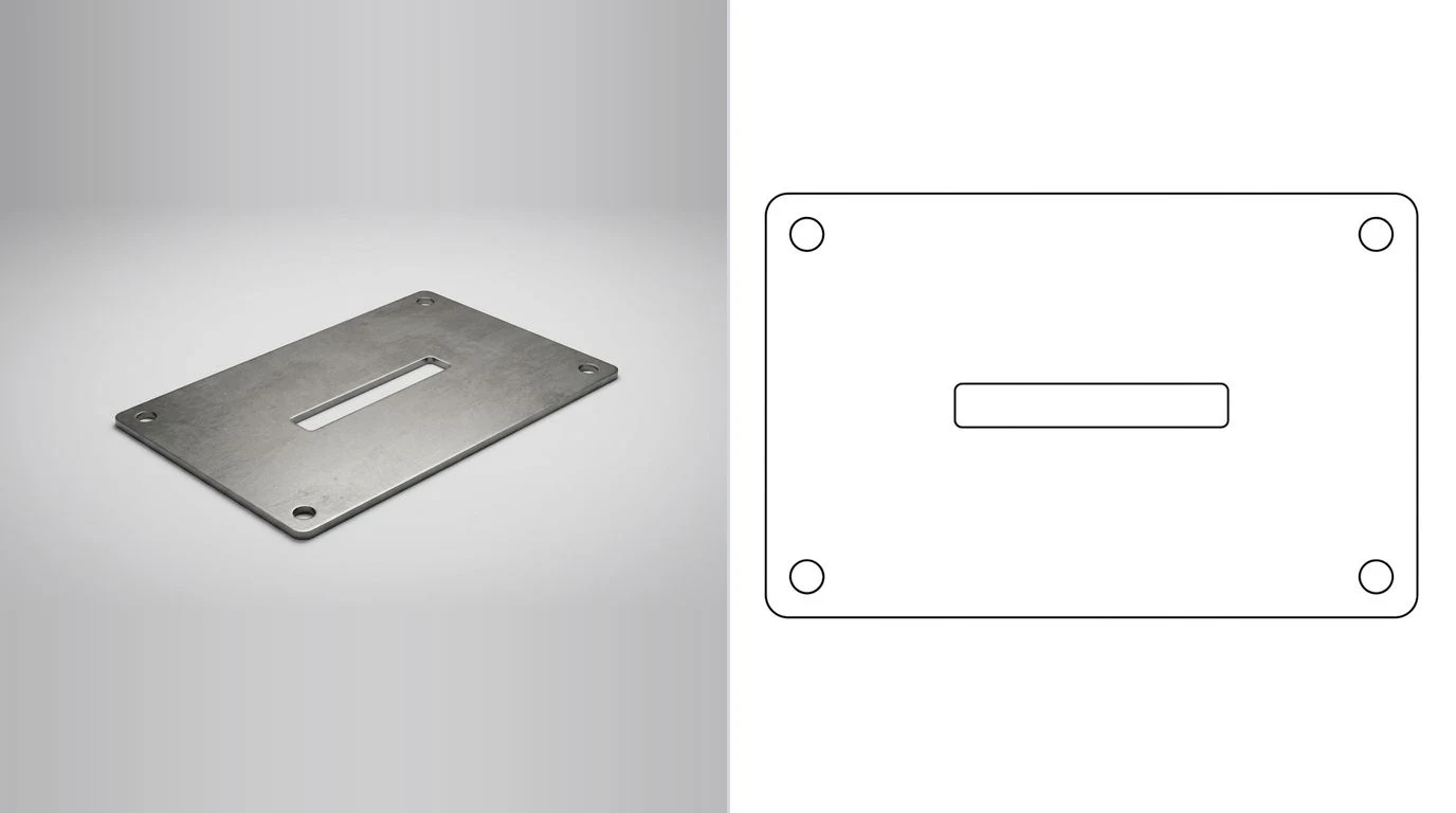
DWG or DXF for the shop?
Once the geometry exists, the export is easy. DWG is AutoCAD's native format, so it is the cleanest choice when your tool can write it and the file is heading back into AutoCAD. DXF is the neutral exchange format almost every CAD and CAM program reads, so it is the safer bet when the file is moving on to a laser, plasma or CNC shop, often as the older R12 version for maximum compatibility. The full comparison is in DWG vs DXF, and if the recipient cannot open what you sent, how to open a DXF file covers the free viewers. The wider map of which format each machine actually wants is in CAD file formats for manufacturing. If what you are digitising is a photograph rather than a scan, the format-specific walkthroughs are JPG to CAD, image to DWG and image to AutoCAD.
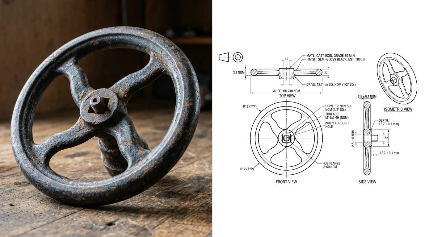
Before you send it
- Did you sort the input first? Clean scan, degraded scan, or no drawing at all. That call decides trace versus rebuild, and it decides everything after.
- Did you clean the scan before tracing? Solid black lines on white, deskewed, stains removed. A tracer only ever copies what you give it.
- Did you scale to one known dimension? Verified against a printed value or a measured feature, not assumed. This is the most common way the job turns into scrap.
- Is the linework clean? Closed profiles, no doubled or stray lines left over from the trace.
- Did you save the right format? DWG for AutoCAD, DXF, often R12, for a shop or a cutter.
Clear that list and a dusty drawing or an orphaned part becomes a real, editable file instead of a scan sitting in a folder. If the drawing is headed for a quote rather than your own screen, what a shop needs beyond the linework is in from a photo to a manufacturing drawing, and the AI route for the lost-drawing case lives at TechDraw AI.
Frequently asked questions
Can you convert a scanned drawing to CAD?
Yes. A clean scan of a line drawing converts well with a raster-to-vector tracer, which turns the black lines into vector geometry you export as DWG or DXF. The catch is that a scan is a picture, so the tracer copies whatever is on the page, including skew, stains and faded lines, and it never recovers the real scale on its own. You always set one known dimension afterwards so the drawing sits at true size.
What is the best Scan2CAD alternative?
It depends on the input. For clean scanned line drawings, free Inkscape traces a bitmap to DXF and most CAD apps open that directly, so you do not always need a paid tracer. For a scan too faded or marked up to trace cleanly, or a part whose drawing is lost entirely, an AI tool that rebuilds a dimensioned drawing from a photo of the real part gives you something a tracer cannot: real measurements rather than a copied outline.
How do I convert a scanned PDF to DWG?
First check whether the PDF is vector or raster. A vector PDF already contains linework, so a PDF-to-DWG converter extracts it cleanly. A scanned PDF is just an image wrapped in a PDF, so it has to be traced like any other raster, then scaled to a known dimension. Export the result as DWG for AutoCAD or DXF for a shop, and verify one measurement before you rely on it.
Can AI convert an old paper drawing to CAD?
For a clean scan, AI raster-to-vector is genuinely fast and good. Where AI changes the game is the harder case: an old part whose drawing is lost or too degraded to read. You photograph the real part, give the tool one reference measurement, and it rebuilds a fully dimensioned drawing you export as DWG or DXF. That is reverse engineering from the object, not tracing a page, and it is often the only route left for legacy parts.
Why does my scanned drawing trace come out messy?
Because a tracer is loyal to the pixels, not to the part. A scan carries paper texture, fold lines, coffee stains, faded ink and skew, and the tracer reads all of it as geometry, so you get doubled lines, broken arcs and speckle. Clean the scan first, raise the contrast so the linework is solid black on white, deskew it, and the trace comes back far cleaner.
Is scanned drawing to CAD accurate?
The shape can be very accurate, the scale is not automatic. Proportions carry over faithfully if the scan is square and undistorted, but a scanned image has no units, so nothing is at true size until you anchor it to one dimension you know. Get one length right, from a printed dimension on the sheet or a measurement off the real part, and every other length follows.