
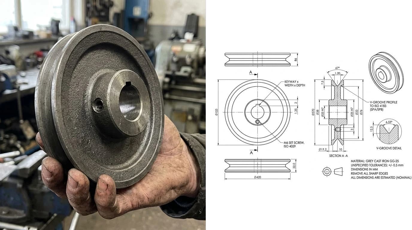
Searching “photo to CAD” usually means you have one thing in hand: a picture of a real part, often snapped on a phone, and you need it as a file you can open, measure and edit. Here is the catch nobody puts on the download button. A photo stores coloured pixels and nothing else, while a CAD file stores lines, arcs and dimensions as math. So this was never a file conversion. You are rebuilding the picture as geometry, then giving that geometry the one thing a photo never carried, a real size. Get both right and you have a drawing you can manufacture from. Skip either and you have a fuzzy outline at the wrong scale.
Our articles are still written by humans!
Get human written articles in your Google feed.
The short answer
Yes, you can convert a photo to CAD, but not with a one-click converter. A photo has no geometry and no scale, so the shape has to be redrawn as lines and then pinned to one real measurement. If your image is flat line art, a logo, a scanned drawing or a screenshot, you vectorize it and export DXF. If it is a photo of a real object, you rebuild it as a dimensioned drawing and scale it to a known length, then save DWG or DXF. Which path you need is decided entirely by what the picture actually is, so that is where we start.
Why a photo is the hard case
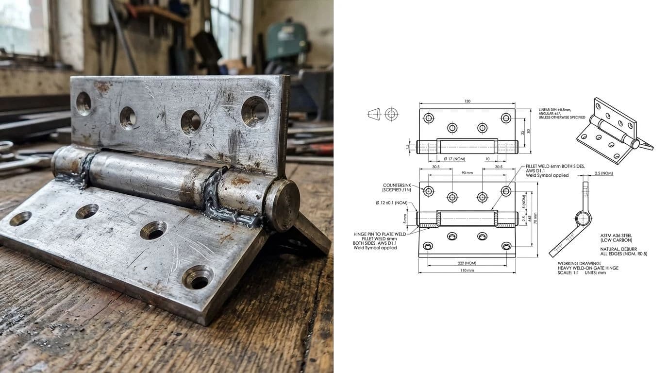
People lump “image to CAD” into one job, but a photo is the hardest input in that family, and it helps to know why before you spend an hour on the wrong route. A scanned drawing or a logo is already geometry. The artwork is the shape, flat and face-on, so a tracer copies it faithfully and the only real work is setting the scale. A photo of a real part is a different animal.
Three kinds of image, three very different jobs
The reason is physical. A camera flattens a three dimensional object onto a grid of pixels, so perspective makes the far side smaller than the near side, lens distortion bows straight edges, and tilt shears the whole shape. Meanwhile there is no depth, no hidden edge and no dimension anywhere in the file. A phone photo adds its own trouble: shadows the tracer reads as edges, and JPG compression halos it traces as fake geometry. None of that is in a clean scan, which is why the same tool that nails a logo can make a mess of a photo. The wider decision across every CAD format sits in the pillar guide, image to CAD: turn a picture into a drawing you can manufacture.
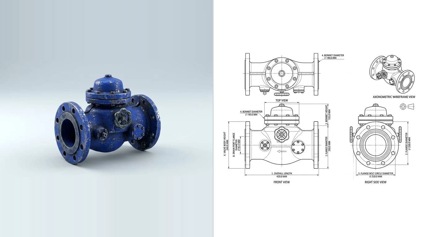
Photo to CAD in four steps
Whichever route you take, the shape of the job is the same. Get these four steps in order and the photo becomes a real file. Get them out of order, most often by leaving scale until last, and you redo the whole thing.
- Sort the image first. Is it flat artwork or a photo of a real object? That single call decides trace versus rebuild, and most bad results trace back to skipping it.
- Turn pixels into lines. Trace it, run a raster-to- vector pass, or let an AI reconstruct the views. This is where the silhouette, or the full geometry, actually gets drawn.
- Anchor it to one real measurement. Pick a feature whose true length you know and scale everything so that length is correct. This is the step that separates a drawing from a picture.
- Export the right format. DWG for AutoCAD, DXF for a shop or a cutter, and check it opened at the size you set before you send it anywhere.
Steps two and three are where the routes differ, so the rest of this guide digs into each. If you want the format-specific angle instead, image to DWG approaches the same conversion from the DWG side and image to AutoCAD walks the AutoCAD workflow end to end.
The manual trace route
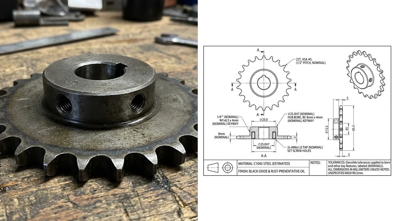
If the photo is simple and you already live in a CAD program, tracing by hand gives you total control. The method is the same in AutoCAD, and close to it in most other tools. Bring the image in, lock its size, then draw over it.
- Attach the photo. In AutoCAD use
ATTACHorIMAGEATTACHand place the picture in the drawing as a background underlay. - Scale it to a known length. Run
SCALE, pick the image, typeRfor Reference, click the two ends of a feature you have measured, and enter the true length. - Fade and lock the image layer so you do not grab it by accident, then trace the edges on a fresh layer with
LINE,PLINE,ARCandCIRCLE. - Freeze or detach the image, add your dimensions, and save. What is left is real, editable geometry.
Honest warning: on a photo of a real object this only ever gives you the outer outline, at whatever angle the camera caught, with no bore, no counterbore and no hidden feature. It shines on flat artwork and simple flat parts, and struggles on anything with depth. If your trace comes out rough, with doubled lines and jagged arcs, that is an input problem, and why a traced image looks jagged and how to fix it covers the cleanup.
The one thing a photo never had: scale
This is where more photo-to-CAD jobs fall apart than anywhere else, and it is baked into the formats themselves. A photo is measured in pixels. A CAD drawing is measured in real units, millimetres or inches. Nothing in a JPG says how many millimetres a pixel is worth, so whatever imports it has to guess, and the guess is almost never your part's real size. It looks fine on screen and comes out wrong at the machine, which is the most expensive place to find out.
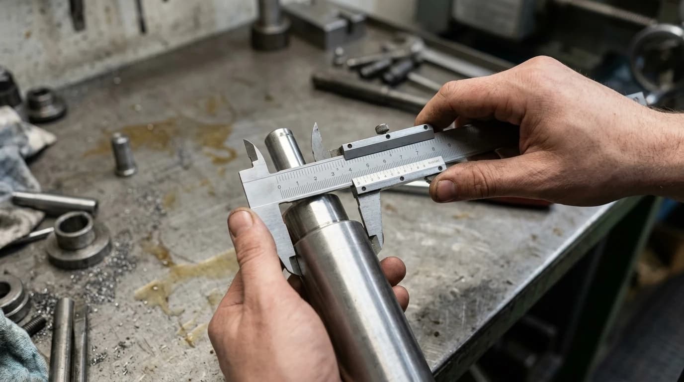
The fix never changes and it is not optional. Find one dimension you know for certain, measured off the real part with calipers or a rule, and scale the whole drawing so that one feature matches the known number. Get a single length right and every other length follows, because the proportions were already correct. That exact idea, in depth, is in how to get dimensions from a photo, and the failure it prevents, a file that imports at the wrong size, is in fixing a drawing that comes in at the wrong size.
DWG or DXF from a photo?
Once the geometry exists, the export is the easy part. DWG is AutoCAD's native format, so it opens with no translation and keeps the most fidelity when a tool can write it. DXF is the neutral exchange format almost every CAD and CAM program can read, and AutoCAD opens it just as cleanly, turning it into DWG the moment you save. In practice, take DWG when it is offered, take DXF when the file is heading to a laser, plasma or CNC shop, and do not lose sleep over the difference for 2D linework.
The full comparison, including when a supplier specifically asks for one or the other, is in DWG vs DXF. If the file is bound for a cutter rather than back into CAD, our image to DXF converter covers the cutter side, and the wider map of which format each machine and shop actually wants is in CAD file formats for manufacturing.
Photo to CAD tools compared
There is no single best tool, only the right one for your image. Here is the honest split, including where each one stops.
Photo to CAD, by tool and by what it can actually deliver
For flat artwork the tracers are genuinely enough, and there is no accuracy to buy by paying, only convenience. Even free Inkscape exports a DXF that opens straight in CAD, and the dedicated tracers are lined up side by side in the best JPG to DXF converters. Where every tracer stops is the photo-of-a-real-part case, because none can supply the two things a picture never held, the real size and the dimensions that come with it.
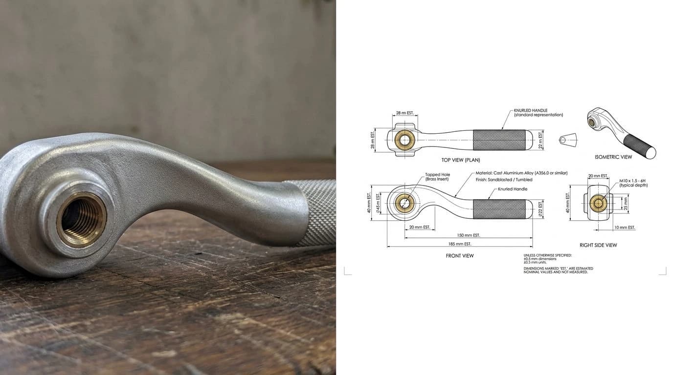
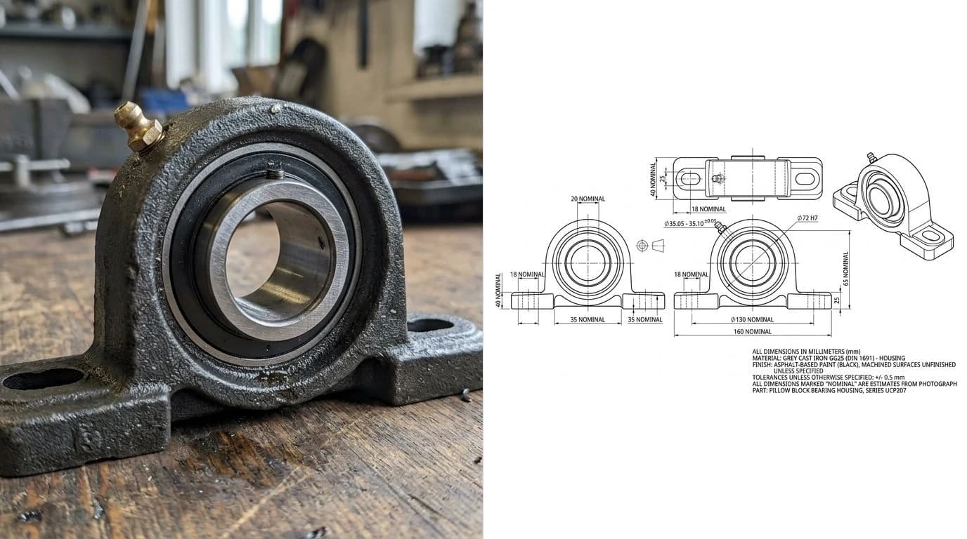
That gap is what TechDraw AI is built for. You upload the photo, type in one real measurement, and it rebuilds a dimensioned technical drawing: orthographic views, closed profiles, every length tied to your reference instead of to pixels. Then it exports a clean DWG, DXF, SVG or PDF you open straight in CAD. It stays honest about the ceiling too. You get a measurable 2D drawing you can edit and quote, not a 3D solid conjured out of one photo. The same idea, working from a real part in your hand rather than a screen, is in how to reverse-engineer a part from a photo, and for folded parts specifically, sheet-metal drawings from a photo goes deeper on bends and flat patterns.
How to shoot a photo that converts
The single biggest lever on the result is not the tool, it is the photo you feed it. Two minutes spent shooting it properly saves an hour of cleanup, whichever route you take. Aim for these.
- Shoot straight on, not at an angle. Get the camera square to the face you care about. Every degree of tilt is distortion the tool has to fight or you have to correct.
- Fill the frame with the part and keep the whole feature in shot. More pixels on the part means cleaner edges to trace or rebuild from.
- Light it flat and even. Soft, diffuse light kills the hard shadows a tracer mistakes for edges. Avoid a single harsh lamp or direct sun.
- Put a known length in the shot, a rule or a caliper jaw, or simply measure one feature and note it. That is your scale anchor, and without it nothing downstream is to size.
- Use the highest quality you can. A sharp, well-lit photo beats a compressed JPG. Compression halos around every edge get read as fake geometry.
Clear that list and whatever route you pick starts from clean input instead of fighting the picture. From there, taking the drawing the last mile to something a shop will actually quote is covered in from a photo to a manufacturing drawing, and if your input is already a JPG rather than a fresh photo, jpg to CAD covers that entry point.
Frequently asked questions
Can you convert a photo to CAD?
Yes, but not by a straight file conversion. A photo stores coloured pixels, while a CAD file stores lines, arcs and dimensions as math, so something has to redraw the shape as geometry. For a flat logo or a scan you vectorize it. For a photo of a real 3D part you rebuild it as a dimensioned drawing and scale it to one known measurement, then export DWG or DXF. There is no button that reads a size off a picture that never had one.
How do I turn a picture into a DWG file?
Three ways work. Trace it by hand in AutoCAD after attaching the image and scaling it to a known length. Run it through a raster-to-vector tool and export DXF, which any CAD app opens and saves as DWG. Or, for a photo of a real part, use an AI tool that rebuilds a dimensioned drawing from your reference measurement and exports the DWG directly. The first two copy the outline; only the third gives you real dimensions.
Is there a free photo to CAD converter?
For flat line art, yes. Inkscape traces a bitmap and exports DXF for free, and most CAD programs open that DXF. Free tracers stop at the visible outline though, so you still set the real scale by hand and there are no inner features or dimensions. For a photo of a real object rather than clean artwork, a free tracer only gives you a silhouette, not a drawing you can manufacture from.
Can AI convert a photo to CAD?
AI is where the photo case finally works, because it does the one thing tracers cannot: rebuild the part as a proper dimensioned drawing instead of copying pixels. You upload the photo, give it one real measurement to scale from, and it returns orthographic views with lengths, diameters and closed profiles as DWG or DXF. It stays honest about the ceiling though. You get an editable 2D drawing, not a 3D solid conjured out of a single photo.
Why does my converted photo come out the wrong size in CAD?
Because a photo has no units. It is measured in pixels, and a CAD drawing is measured in millimetres or inches, so whatever imports the image has to guess the scale and the guess is almost never right. The fix is to find one dimension you know for certain, measured off the real part or printed on a drawing, and scale the whole thing so that one feature matches its true length. Every other measurement then follows.
What is the difference between photo to CAD and image to CAD?
They overlap, but the input differs. Image to CAD covers any raster, including clean scans, screenshots and logos that are already flat line art and trace faithfully. Photo to CAD is the harder subset: a real photograph of a physical object, usually from a phone, where perspective, lighting and the lack of any scale all fight you. A scan is close to geometry already, a photo is not.