
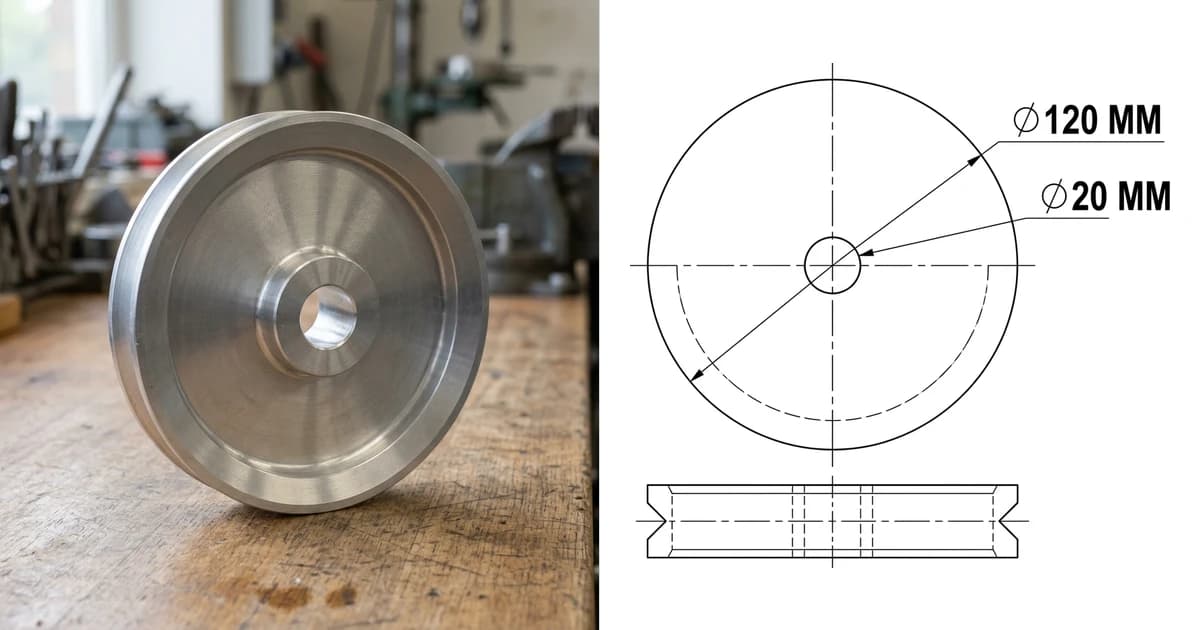
A STEP file is a 3D model saved in an open, standardised format that almost every CAD program on earth can read. Someone has sent you a .step or a .stp, you want to know what it is, whether you need expensive software to open it (you do not) and what to do with it. Here is the whole answer, including the part most articles skip: what a STEP does not carry, and why the shop asks for a drawing as well.
Our articles are still written by humans!
Get human written articles in your Google feed.
The short answer
In the 1980s every CAD system stored models in its own private format, and moving a part from one to another meant redrawing it. ISO started work on a common language for product data in 1984, and the result, ISO 10303, is what everyone calls STEP. The file you receive is written according to Part 21 of that standard, the clear text encoding, which is why a STEP file is a text file you can open in Notepad and actually read.
Three practical things follow. It is neutral, so SolidWorks, Fusion, Inventor, Creo, NX, CATIA, Rhino, Onshape, FreeCAD and every other serious CAD tool import it without a converter. It is exact, so unlike a mesh it describes true curved surfaces and can be machined from directly. And it is lossy in a specific way: you get the finished shape, not the recipe that built it.
What is actually inside a STEP file
Open a .step in a text editor and you will see a header followed by thousands of numbered lines. That is a boundary representation, or B-rep: the model described as a watertight skin of surfaces with the topology that says how they join. Roughly, it contains:
- Exact surfaces. Planes, cylinders, cones, spheres, tori and NURBS patches, each with real parameters. A 20 mm bore is a cylindrical surface with a radius of 10 at a known axis, which is why your CAD can tell you it is exactly 20 mm however far you zoom in.
- Topology. Faces, edges, vertices and loops, and how they connect into shells and solids. This is what makes a STEP a solid body rather than a bag of loose surfaces.
- Assembly structure. Parts, sub-assemblies, names and the transformation matrices that place each component, so an assembly arrives assembled rather than as a pile of parts at the origin.
- Units and a coordinate system. Declared in the file itself. This is a genuine advantage over DXF and STL, both of which are unitless in practice and cause the classic wrong size on import problem.
- Colour, materials and annotations, sometimes. Depends entirely on the application protocol, which is the next section.
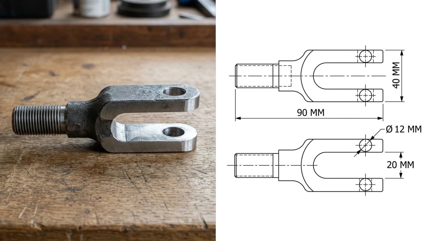
The one thing people are surprised by is what is missing: feature history. The extrusion, the fillet, the pattern, the sketch dimensions that drove them, none of that survives. You receive a finished solid, sometimes called a dumb solid, and you can push and pull it with direct editing tools but you cannot change the number that made it. If you need the history, you need the native file.
STEP or STP, and what the header tells you
.step and .stp are the same format. The short one survives from the days of three character extensions, and you can rename either to the other without breaking anything. You may also meet .p21, and since the 2016 edition of Part 21 a compressed archive form usually written .stpZ.
The useful trick is that the file is readable. Open it in any text editor and the first dozen lines tell you what you have:
What the top of a STEP file says
AP203, AP214 and AP242
ISO 10303 is enormous, so it is split into application protocols: subsets aimed at a particular industry and job. Three matter for mechanical work.
The STEP application protocols you will actually meet
AP242 arrived in 2014 and is where the standard is going: its point is model based definition, the idea that the 3D model carries the tolerances and notes so the 2D drawing becomes optional. The honest status in 2026 is that the file format supports it, the big CAD systems can write it, and most of the tools your supplier actually uses to look at your model will show you the shape and quietly ignore the annotations. Which is why the drawing has not gone anywhere yet.
STEP vs STL, DWG and DXF
These four cover most of what gets emailed around a workshop, and they do genuinely different jobs.
STEP next to the formats it gets confused with
The distinction that trips people up is exact versus approximated. Export the pulley on this page as STL and its groove becomes a few hundred flat facets that are close to round; export it as STEP and the groove stays a cone with an angle. Going from STEP to STL is a one way street, and the trip back is the subject of STL to STEP, which is more complicated than the converters admit. The 2D side of the family is covered in STEP vs DXF, DWG vs DXF and what a DWG file is, and the whole map lives in CAD file formats for manufacturing.
How to open a STEP file
Start by deciding whether you need to look at the model or work on it, because the free options are good at both but they are different tools.
Just to look, measure or check it
- Autodesk Viewer in a browser. Upload the file, rotate it, measure it, take a section. Nothing to install, works on Windows, Mac, Linux and a tablet.
- eMachineShop and similar browser viewers do the same job with no account. Fine for a quick check, less good for anything confidential, since the file leaves your machine.
- 3D-Tool Free Viewer on Windows if you would rather keep the file local and still only view it.
To actually work on it, free
- FreeCAD. Free, open source, Windows, Mac and Linux. Its STEP import is the Open Cascade kernel, which is the same machinery several commercial products license, so the geometry comes in as a real solid rather than a shell. It also exports STEP, and its TechDraw workbench makes the 2D drawing. This is the answer for most people who do not already own CAD.
- Onshape. Full parametric CAD in a browser with a free plan for public documents. Good if you want to modify the part and have no wish to install anything.
- Fusion 360, free for personal use. Opens STEP, converts to a mesh, generates toolpaths in the same file.
More of the free options, and what each one is genuinely good at, are in the best free CAD programs.
Paid CAD, which all read it natively
SolidWorks, Inventor, Creo, NX, CATIA, Solid Edge, Rhino, Shapr3D, BricsCAD and Alibre all import and export STEP. That is the entire point of the format, and it is the reason a supplier will ask for one rather than for your native file.
How to convert a STEP file
STEP to STL or 3MF, for printing
Every CAD program can do this on export, and the setting that matters is the mesh tolerance, called deviation or chord height. Too coarse and your cylinder becomes a polygon; too fine and you get a 400 MB file for no visible benefit. In FreeCAD it is in the export options, in Fusion it is Save As Mesh with a refinement setting. Worth knowing: most current slicers, PrusaSlicer, Bambu Studio and Orca among them, now import STEP directly and mesh it themselves, which is one less step and usually a better mesh. Whether you then keep the result as STL or 3MF is covered in 3MF vs STL.
STEP to DWG, DXF or PDF
This is a projection, not a conversion: you are making a drawing of the model. FreeCAD's TechDraw and Fusion's drawing workspace both place views, add dimensions and export DXF, DWG or PDF. The one case that is a true conversion is sheet metal, where you unfold the model and export the flat pattern as a DXF that goes straight to a laser. If you are handed a DXF and need to check it, the browser tools here open one without any CAD: DXF viewer and DXF to PDF.
STEP to a native CAD file
Just open it and save as. You keep the geometry and you do not get a feature tree, whatever the software claims. Some packages offer feature recognition, which reverse engineers simple extrusions and holes back into features and works well on prismatic parts and poorly on organic ones.
The direction that is not a conversion at all
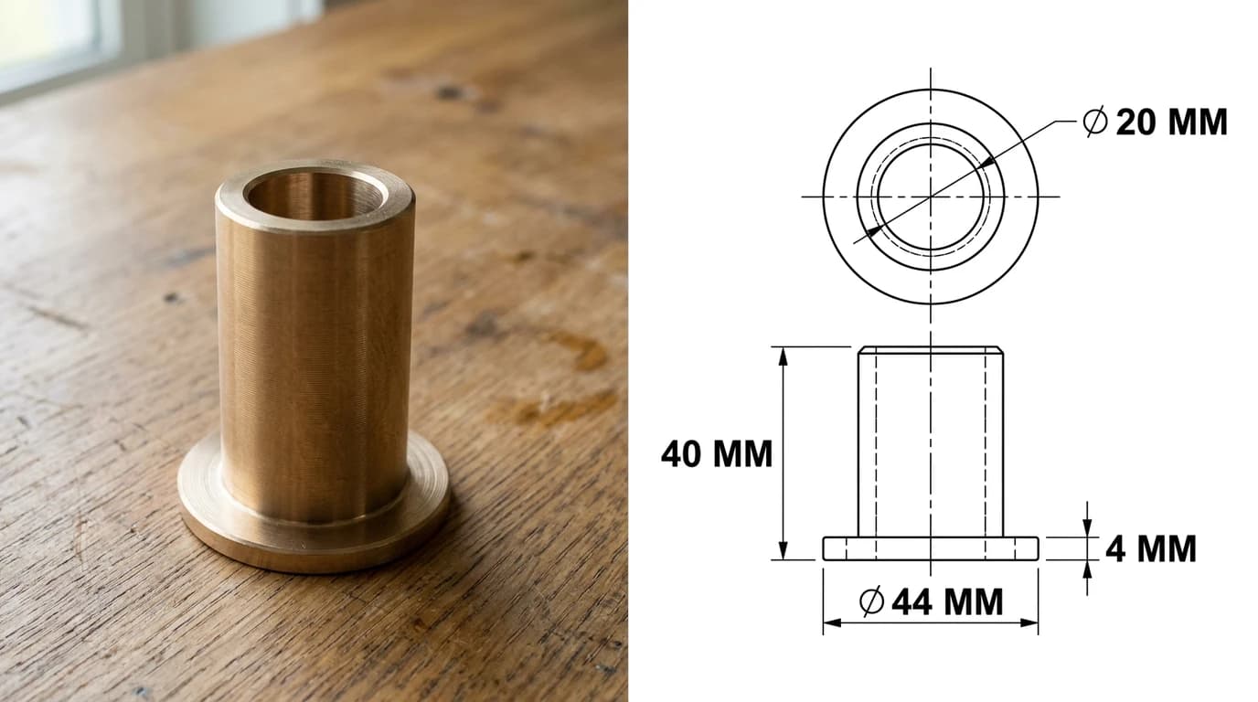
Going from a photograph, a scan or a paper drawing to a STEP is not converting, it is modelling: there is no geometry in a picture to convert. Something has to interpret the image and build real geometry from it, which is what reverse engineering a part walks through, and what scan to CAD covers for scanned drawings.
When a STEP file imports badly
STEP is reliable, which makes the exceptions memorable. Almost all of them are one of these.
- It comes in as surfaces, not a solid. The exporter wrote a shell that does not close, often because of tiny gaps between faces. Run your CAD's heal, sew or stitch command. If that fails, ask for a re-export from the original system at a tighter tolerance.
- The assembly is one lump, or explodes into loose parts. Assembly structure depends on both the protocol and the importer. Ask for AP242, and check whether your import dialog has a setting for keeping the hierarchy.
- Everything is grey. AP203 carries no colour. If the colours matter, ask for AP214 or AP242.
- The model is a long way from the origin. Common with parts exported from a large assembly or from architectural software with real world coordinates. Move it to the origin after import, before you start modelling.
- The size looks wrong. Rarer than with DXF, because STEP declares its units, but it happens when an exporter writes inches while labelling millimetres. Measure one known feature straight after import; a 25.4 factor makes the cause obvious.
- The tolerances are not there. They may be in the file as AP242 PMI and simply not displayed. Most viewers ignore PMI. Assume the recipient will not see it and send a drawing.
When to send a STEP, and what to send with it
Send a STEP when the other person will do 3D work: quoting a machined part, programming toolpaths, designing a mating part, checking a fit, printing a prototype. It is the least ambiguous thing you can hand someone, because it is a shape rather than an interpretation of one.
Then send the drawing with it. A STEP tells the shop what the part looks like; it does not say which of those dimensions is critical, what tolerance the bore needs, which face gets machined flat, what the surface finish should be, or what material to use. Every shop we have talked to says the same thing: the model plus a dimensioned PDF gets quoted, the model on its own gets a reply asking for the drawing. What that drawing has to contain is set out in what makes a drawing manufacturing ready.
If you have the part but not the drawing, that is the gap TechDraw AI fills: photograph the part or upload an image, and it produces a dimensioned 2D technical drawing you can export as DWG, DXF, SVG or PDF and send alongside the STEP. It does not write STEP files, and it is not trying to; the 3D model is the half you usually already have.
Upload a photo of the part and get a dimensioned 2D drawing to send with your STEP file.
Turn a photo into a drawingFrequently asked questions
What is a STEP file?
A STEP file is a 3D CAD model saved in a neutral, open format defined by ISO 10303, which is why almost every CAD program can open one. STEP stands for Standard for the Exchange of Product model data. Inside is a plain text description of exact solid geometry: faces, edges and surfaces such as planes, cylinders and NURBS, plus the assembly structure and, depending on the version, colours and tolerances. Because the geometry is exact rather than approximated, a STEP file can be edited and machined from, unlike a mesh format such as STL.
What is the difference between a .step and a .stp file?
Nothing. They are the same format with two spellings of the same extension. The three letter .stp version exists because older systems only allowed three characters after the dot. Rename a .stp to .step or the other way round and every CAD program will still open it. Some tools also write .p21, and ISO 10303-21:2016 allows a zipped exchange structure, usually seen as .stpZ.
How do I open a STEP file for free?
For a quick look, upload it to a browser viewer such as Autodesk Viewer, which needs nothing installed and works on any operating system. To actually work with the model, install FreeCAD, which is free, open source and imports STEP natively on Windows, Mac and Linux, or use a free account on Onshape in the browser. Fusion 360 also opens STEP and is free for personal use. Windows Preview, macOS Preview and the Windows 3D Viewer do not read STEP.
Is a STEP file better than an STL?
For engineering, yes. A STEP stores exact geometry, so a 20 mm bore is a cylinder of radius 10 that CAD can measure, fillet and edit. An STL stores a triangle mesh that only approximates that bore, carries no units and cannot be edited as a solid. For 3D printing an STL or a 3MF is what the slicer wants, though most modern slicers now import STEP too and mesh it themselves. Send STEP when someone will engineer from the model, send STL or 3MF when someone will print it.
Can I edit a STEP file?
Yes, but not parametrically. Any CAD program can open a STEP and modify the solid directly: cut it, add features, change it with direct editing tools. What does not travel is the feature history, so you cannot go back and change the sketch that made the boss, because the sketch is not in the file. That is the trade for a format everything can read. If you need the history, ask for the native file, a SolidWorks SLDPRT or a Fusion archive.
What is the difference between AP203, AP214 and AP242?
They are application protocols, the flavours of STEP. AP203 is the older mechanical design protocol and carries geometry and assembly structure but no colour. AP214 came from the automotive industry and adds colours, layers and materials. AP242 merged the two in 2014 and is the current one, adding machine readable product manufacturing information such as dimensions and tolerances, plus kinematics. If your CAD program offers AP242 on export, use it, and fall back to AP214 if the receiving software is old.
Can I convert a STEP file to DWG or DXF?
You can, but understand what you are asking for. A STEP is a 3D solid and a DXF or DWG is normally a 2D drawing, so the conversion means projecting views of the model and dimensioning them. In FreeCAD that is the TechDraw workbench, in Fusion 360 it is the drawing workspace, and both export DXF, DWG or PDF. A flat sheet metal part is the one honest exception: unfold it and the flat pattern exports straight to DXF for cutting.
Does a machine shop want a STEP file or a drawing?
Both, and for different reasons. The STEP gives the programmer the exact shape to generate toolpaths from, which saves hours of redrawing. The 2D drawing carries the things geometry alone cannot say: critical dimensions and tolerances, surface finish, material, thread callouts, and which face matters. Sending only a STEP is the most common reason a shop comes back with questions before quoting.
Sources
- ISO 10303-21:2016, Part 21: Clear text encoding of the exchange structure
- Library of Congress, Sustainability of Digital Formats: STEP-file, ISO 10303-21
- STEP Tools: ISO 10303 Part 21 edition 3, final specification
- MBx Interoperability Forum (AFNeT, PDES Inc., prostep ivip): STEP translator testing
- FreeCAD: free open source CAD with native STEP import and export