ChatGPT will not draw you a dimensioned, manufacturing-ready part, and any prompt that promises otherwise is selling you a picture, not a drawing. What it is genuinely good at is everything around the geometry: planning the views, reasoning about dimensions and tolerances, decoding GD&T, writing the notes and title block, and generating simple geometry as SVG or DXF code you can import. Used that way, it is a fast, tireless drafting assistant. Below are 20 prompts that actually work, grouped by the job they do, each ready to copy, paste and fill in.
How to use these prompts
A prompt is only as good as what you put into it. Four habits make every prompt below work far better:
- Give it a role and a standard.“Act as a mechanical drafter working to ASME Y14.5” sets the register and the conventions.
- Be specific with real numbers. Replace every
[BRACKET]with the actual part, dimensions, material and process. Vague in, vague out. - Ask for one thing at a time. Views first, then dimensions, then tolerances. Bundling everything into one prompt produces a shallow answer to each part.
- Verify before you build. Treat every output as a first draft to check, especially tolerances and any generated geometry.
If you want to see how far the chatbot actually gets on its own first, we put it through a real test in can ChatGPT make technical drawings. And if you live in a different chatbot, there are parallel prompt libraries for Gemini, Claude and Grok. And if your day lives inside AutoCAD, there is a dedicated set of ChatGPT prompts for AutoCAD covering AutoLISP and scripts.
Plan the drawing
This is where ChatGPT earns its keep. Before any geometry exists, it can help you decide what the drawing needs to say, the same order we follow in how to make a technical drawing.
 Photo
Photo Drawing
1. Choose the right views
Stops you over- or under-drawing a part.
Act as a mechanical drafter working to ASME Y14.5. I need to draw this part: [DESCRIBE PART, e.g. an L-shaped steel mounting bracket, 80 x 60 x 40 mm, with two Ø8 holes]. List the minimum set of orthographic views that fully defines it, tell me which face should be the front view and why, and say whether I need any section or detail views.
2. Plan the dimensioning scheme
Gives you a datum strategy before you place a single dimension.
For this part [DESCRIBE / LIST FEATURES], propose a dimensioning scheme: which edges or faces to use as datums, whether to use baseline or chain dimensioning for each feature group, and the order to dimension features so that every feature is defined exactly once and nothing is over-dimensioned.
3. Decide a tolerance strategy
Separates the features that need precision from the ones that do not.
Recommend a tolerancing strategy for this machined part [DESCRIBE]. Suggest a sensible ISO 2768 general-tolerance class for the bulk of the dimensions, then list which specific features (mating diameters, hole positions, sealing faces) should get tighter individual tolerances, with a suggested value and the reason. Flag where I should consider GD&T instead of plus/minus.
4. Turn a description into a drawing spec
Converts a paragraph of intent into a structured starting point.
Convert this plain-English part description into a structured drawing specification with sections for Views, Key dimensions, Tolerances, Material, Surface finish and General notes. Ask me up to 5 clarifying questions first if anything critical is missing. Description: [PASTE].
Symbols, standards & GD&T
Anything that is fundamentally language, symbols, standards, definitions, is squarely in ChatGPT's wheelhouse. Pair these with our engineering drawing symbols and GD&T guide when you want a human-written reference too.
 Photo
Photo Drawing
5. Explain a GD&T callout
Decodes a feature control frame into plain English.
Explain this GD&T feature control frame in plain English: [e.g. position 0.2 (M) | A | B(M) | C]. Tell me the characteristic being controlled, the tolerance zone, what the material condition modifiers mean here, and which datums it references and in what order.
6. Pick the right GD&T control
Turns a functional requirement into the correct symbol.
I need to control the following on a part: [REQUIREMENT, e.g. that a bore stays perpendicular to the mounting face within 0.1 mm]. Which GD&T characteristic should I use, what datums do I need, and write the feature control frame I should put on the drawing. Explain the choice in one sentence.
7. Decode unfamiliar symbols and abbreviations
Clears up the shorthand on someone else's drawing.
I'm reading a technical drawing with these symbols and abbreviations: [LIST, e.g. ⌀, R, THRU, CBORE, TYP, SF, ±]. Explain what each one means and what it tells the machinist. Note any that differ between ISO and ASME conventions.
8. Check first-angle vs third-angle projection
Avoids a part being machined back to front.
Explain how to tell first-angle from third-angle projection on a drawing, how the projection symbol looks for each, and exactly how a part would come out wrong if I read a third-angle drawing as first-angle. Then tell me which convention is standard in [COUNTRY/REGION].
Notes & title block
The repetitive, boilerplate-heavy parts of a drawing are perfect for an LLM. These produce text you can drop straight onto the sheet, then check against our manufacturing-ready checklist.
 Photo
Photo Drawing
9. Write a general-notes block
Produces a shop-ready notes block in seconds.
Write a concise, shop-ready general-notes block for a machined [MATERIAL, e.g. 6061-T6 aluminium] part. Cover: default general tolerance, break-all-sharp-edges, surface finish, deburring, any coating/plating, and inspection requirement. Keep it to numbered notes in the style used on real production drawings.
10. Draft the title-block content
Fills in the fields that stop expensive mistakes.
Generate the fields and example content for a title block for: part name [NAME], part number [NUMBER], scale [e.g. 1:2], units [mm], projection [third-angle], material [MATERIAL], finish [FINISH], drawn by [NAME], revision [A]. List the fields a complete title block should always include.
11. Build a tolerance stack-up
Checks whether a dimension chain actually fits.
Do a tolerance stack-up for this dimension chain in an assembly. Show both the worst-case and the statistical (RSS) result, the steps, and the resulting nominal gap with its tolerance. Tell me if the gap can go negative (interference). Chain: [LIST each dimension as nominal ± tolerance].
12. Convert and clean up a dimension table
Handles unit conversion without arithmetic slips.
Convert this dimension table from inches to millimetres, keep two decimal places, and flag any value that lands within 0.1 mm of a standard metric size (so I can consider rounding to it). Return it as a table with columns Feature, Original (in), Converted (mm), Note. Table: [PASTE].
Generate geometry as code
This is the closest ChatGPT gets to actually “drawing”. Because SVG and DXF are text formats, it can write them, and code like OpenSCAD or matplotlib can produce real geometry. It is reliable only for simple shapes, and it cannot judge scale, so always import and check.
 Photo
Photo Drawing
13. Generate a clean SVG outline
Good for logos and simple flat profiles.
Write clean, minimal SVG for the 2D outline of [SHAPE WITH DIMENSIONS, e.g. a 100 x 60 mm plate with a Ø20 mm hole centred]. Use millimetres as user units (width/height in mm), closed paths only, no fills or styling, and put the origin at the bottom-left. Output only the SVG code.
14. Generate a minimal DXF to import
A starting cut file you refine in CAD or our converter.
Generate a minimal ASCII DXF (AutoCAD R12) containing this geometry: [e.g. a 100 x 60 rectangle with a Ø20 circle centred]. Use only LINE, CIRCLE and LWPOLYLINE entities, set units to millimetres, and make all profiles closed. Output only the DXF text so I can save it as a .dxf file.
15. Build a parametric model in OpenSCAD
Lets you tweak dimensions and re-export.
Write OpenSCAD code for a parametric [PART, e.g. spacer / bracket] with named variables for every dimension [LIST DIMS]. Comment each variable, keep it printable/exportable, and structure it so I can change one number and regenerate. Note how to export it to STL and to a 2D DXF profile.
16. Plot a dimensioned view in Python
Produces a quick reference view as a PDF.
Write a Python script using matplotlib that draws the front view of [PART WITH DIMENSIONS] to scale, adds dimension lines with extension lines and arrowheads for the main sizes, sets equal aspect ratio, and saves the result as a vector PDF. Include comments so I can adjust dimensions.
Review, DFM & reverse engineering
A second set of eyes that never gets tired. These catch problems before a part is quoted or cut, and help when you are working from a physical part or a photo rather than a model.
17. Run a design-for-manufacturing review
Flags features that are slow or expensive to make.
Act as a design-for-manufacturing reviewer for [PROCESS, e.g. 3-axis CNC milling]. Given these features [LIST, e.g. internal corners R1, a 30 mm deep narrow pocket, a tapped hole near an edge], flag anything difficult, slow or costly to manufacture, explain why, and suggest a cheaper alternative for each.
18. Find missing or contradictory information
Surfaces the questions a shop would email you.
Review this drawing for information a machine shop would have to query before they could quote or make the part: missing dimensions, untoleranced critical features, no material or finish, no projection symbol, ambiguous notes. List each gap as a question the shop would ask. Drawing details: [PASTE notes/dimensions, or attach the drawing image].
19. Reverse-engineer from measurements
Turns caliper readings into a clean spec.
I measured these features off a physical part with calipers: [LIST measurements]. Help me turn them into a clean dimensioned specification: suggest the likely nominal sizes (e.g. a 9.98 mm shaft is probably 10 mm), identify probable standard fits, and list what else I still need to measure.
20. Plan the photo-to-drawing workflow
Maps the whole route when all you have is a snapshot.
I have only a photo of a part and need a manufacturing drawing and a DXF from it. Lay out the exact step-by-step workflow to get there, including how to establish scale from the photo, what to measure, which steps a person must do versus what a tool can automate, and how to verify the result before sending it to a shop.
 Photo
Photo Drawing
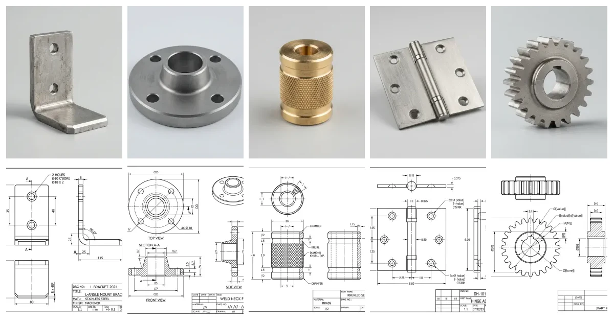
The drawings paired with the photos throughout this post are generated illustrations, not inspection-grade output — the point is the workflow, not the exact values. Always verify dimensions against the real part.
Where ChatGPT stops and a real tool starts
Every prompt here works because it plays to what a language model is good at: language, structure, code and reasoning. The one thing it cannot do is produce accurate, scaled geometry of your actual part. It cannot measure, it cannot hold a tolerance, and it has no idea whether its output is the right size. That is not a prompt you can write your way around; it is the boundary of the tool.
So the workflow that actually ships parts is a hand-off. Use ChatGPT for the thinking and the text. Use a purpose-built tool for the geometry: our photo to manufacturing drawing workflow and image to DXF converter turn a real part or image into editable, dimensionable output. For the wider landscape of what each tool is for, see the best AI technical drawing tools, and to understand the limits first-hand, our ChatGPT test.
Get the division of labour right and ChatGPT stops being a novelty that draws wobbly boxes and becomes what it should be: the fastest drafting assistant you have ever had, sitting next to a tool that does the part it cannot.
Frequently asked questions
Can ChatGPT create a technical drawing?
Not a real, dimensioned, manufacturing-ready one. ChatGPT cannot produce precise CAD geometry, so it will not hand you a drawing a shop can build from directly. What it does well is the thinking and the text around a drawing: planning the views, proposing a dimensioning and tolerance strategy, decoding GD&T, writing notes and title-block content, and even generating geometry as SVG or DXF code that you import and correct. Treat it as a fast assistant, not a drafter.
Can ChatGPT output a DXF or CAD file?
It can generate the text of a simple DXF or SVG, since both are text-based formats, and you can save and import that into CAD. But it is only reliable for basic geometry such as rectangles, circles and simple polylines, and it cannot judge scale or fit. For anything beyond a simple shape, generate the geometry with a purpose-built tool and use ChatGPT for the surrounding work.
What is the best ChatGPT prompt for engineering drawings?
There is no single best prompt; the best results come from giving ChatGPT a role, the exact part with real dimensions, the manufacturing process, and the standard you work to, then asking for one thing at a time. The 20 prompts in this guide are written that way, with placeholders you fill in. The planning and review prompts tend to be the most useful day to day.
Can ChatGPT read or interpret an existing drawing?
With image input it can read a drawing image and summarise views, dimensions, notes and symbols, which is useful for a quick interpretation or a sanity check. It can misread small text, stacked dimensions and faint symbols, so verify anything that matters against the original before you quote or cut a part.
Is ChatGPT accurate for GD&T and tolerances?
It is good at explaining GD&T and suggesting which control to use, because that is language. It is not a substitute for engineering judgement on tolerance values: it cannot know your fits, loads or function, so it may suggest tolerances that are too loose or needlessly tight. Use it to draft and learn, then set the numbers yourself.