
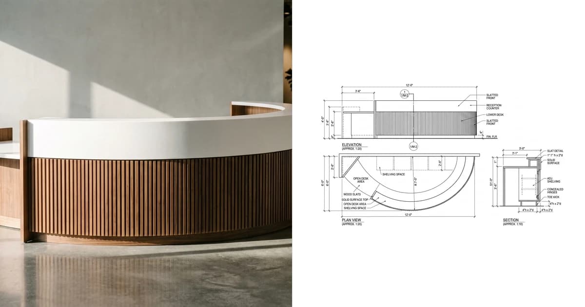
A millwork submittal comes back with one word written across it and that word decides your next three weeks. Most sets that get kicked back are not badly drawn. They are drawn beautifully and quietly missing one thing the reviewer needed: a section deep enough to read, a duty level nobody specified, a dimension taken off the architect's plan instead of off the wall. This is what belongs on the sheet, and what an approval stamp does and does not do for you afterwards.
Our articles are still written by humans!
Get human written articles in your Google feed.
What a millwork shop drawing is
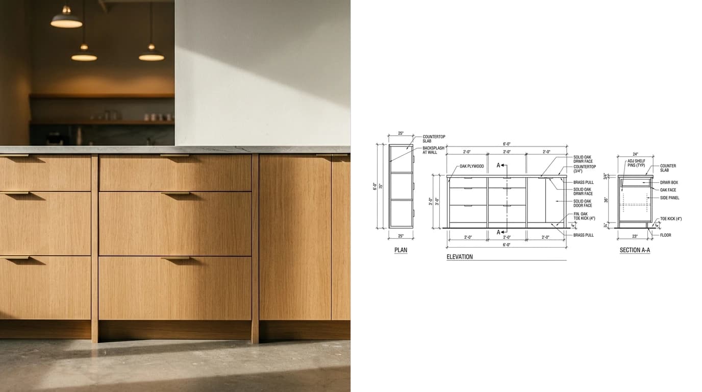
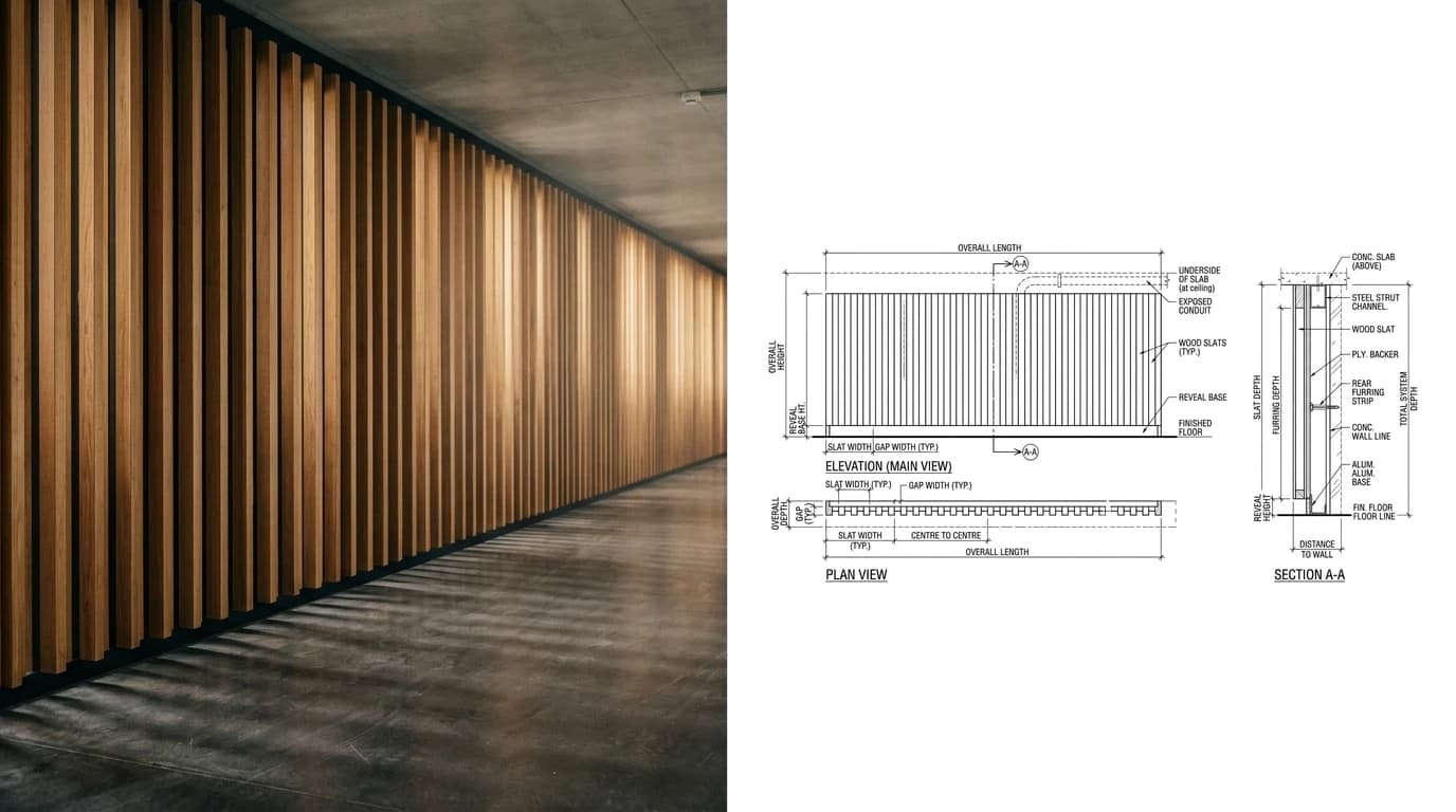
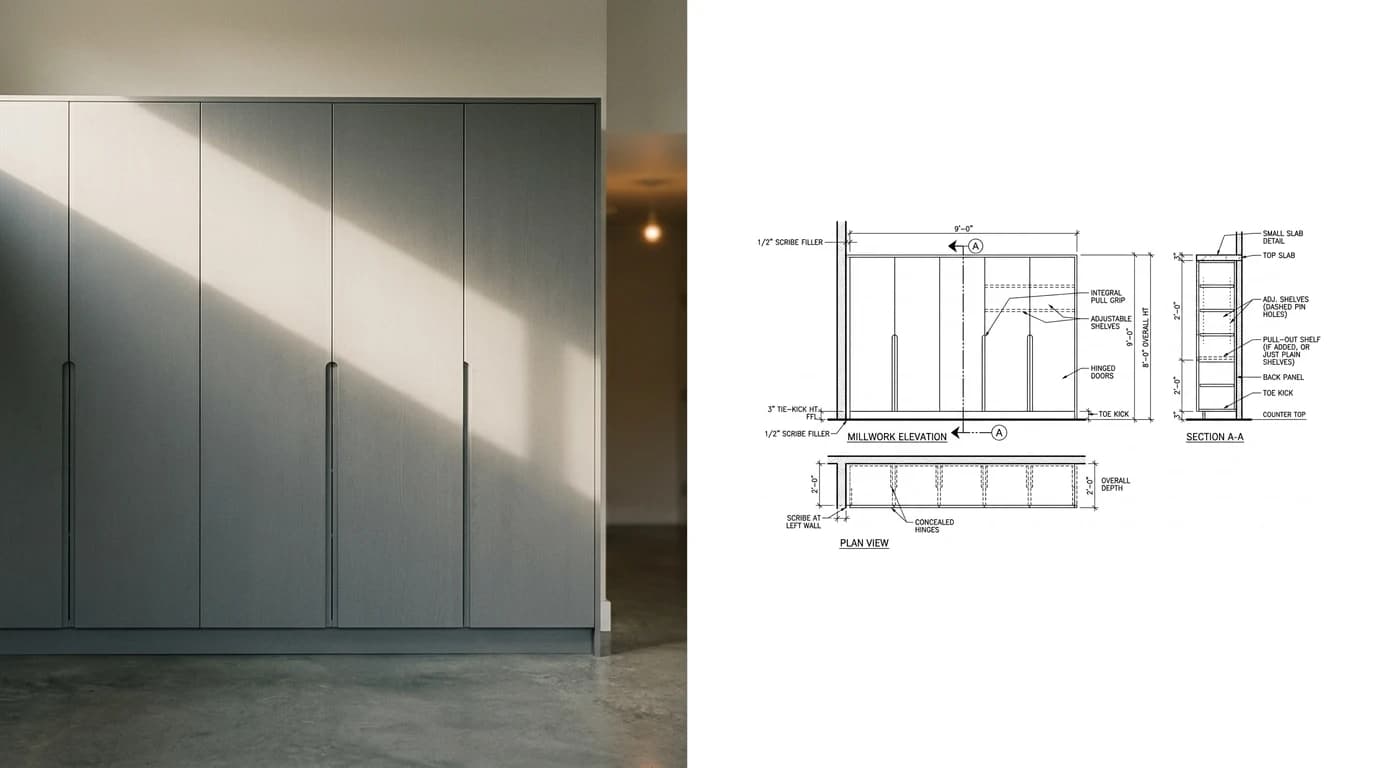
A millwork shop drawing is the fabrication document for custom interior woodwork. It covers the things a job cannot buy off a shelf: reception desks, casework runs, wall panelling, feature stairs, custom doors and running trim. Its single purpose is to show, before anything is cut, exactly what the shop intends to build and how it will meet the building.
That last clause is the one people underestimate. A piece of millwork is not a product sitting in space. It lands against walls that are out of plumb, floors that fall away, and adjacent trades that got there first. The drawing has to show the scribe, the filler, the blocking and the tolerance that absorbs all of it, which is why a millwork sheet looks so different from a furniture drawing even when the object looks similar. If you are drawing freestanding pieces rather than installed work, the furniture shop drawings guide is the closer fit.
Why it isn't the architect's drawing
The architect's drawings express design intent. They say what the finished space should look like and perform like. They are deliberately not a fabrication document, and treating them as one is how shops end up building the wrong thing precisely to the wrong drawing.
Two different documents with different jobs
The practical consequence: your set has to resolve things the design drawings left open, and it has to make those resolutions visible so a reviewer can accept or reject them. A shop drawing that hides its decisions inside a nicely rendered elevation is asking the reviewer to approve something they cannot see.
Millwork, casework, joinery
These get used interchangeably on site and they are not the same thing, which matters the moment a specification cites a standard.
- Casework is the box. Standardised cabinet units, base and wall and tall, built to repeatable sizes. This is what
ANSI/AWI 0641governs. - Millwork is the wider family of custom-fabricated interior woodwork. Casework is part of it, but so are reception desks, panelling, custom doors and trim. On a real submittal you are usually drawing both.
- Joinery is the British and Commonwealth term for roughly what North America calls millwork. If a spec says joinery and cites AWI, someone has mixed two vocabularies and it is worth an RFI rather than an assumption.
What the set has to contain
A complete millwork submittal is a set, not a sheet. The reviewer is looking for a specific sequence and gets uneasy when part of it is missing.
- Cover and index with the project, the spec section, the revision number and what is included. Reviewers reject sets they cannot navigate.
- Key plan locating every piece against the building grid or room numbers, so an elevation can be tied to a place.
- Plans and elevations of each item, typically 1/2 or 3/4 inch to the foot, dimensioned overall and to every opening.
- Sections cut through the carcass, at 1-1/2 or 3 inch to the foot, showing panel thicknesses, tops, toe kicks, reveals and how the piece meets floor and wall.
- Details for anything a section cannot resolve: mitres, waterfall returns, edge conditions, integrated lighting, transitions between materials.
- Schedules for hardware, finish and materials, with real manufacturer model numbers rather than a category.
- Notes covering field verification status, grade and duty level, fire rating where applicable, and anything you are proposing as a deviation.
The dimension rules are ordinary drafting discipline, and if your team is inconsistent about them the guide to dimensioning a technical drawing covers the conventions worth standardising on. The broader bar a fabrication drawing has to clear is in what makes a drawing manufacturing-ready.
Grades and duty levels
Here is the thing a surprising number of sets still get wrong, six years on. Older specs and older drawings reference the Architectural Woodwork Standards (AWS) Edition 2 from 2014, where a single grade of Economy, Custom or Premium carried both how a cabinet looked and how strong it was.
That is no longer the standard for casework. ANSI/AWI 0641, effective 1 June 2020, succeeded and replaced Section 10 of AWS Edition 2, and it separated the two ideas for the first time.
ANSI/AWI 0641: two specifications, not one
The duty levels came out of testing at the AWI National Testing Center in Americus, Georgia, measuring the force and pressure a unit can take. Because appearance and performance are now independent, a project can specify a Premium-looking cabinet at a modest duty level, or a plain Economy cabinet built to take heavy institutional use. Both are valid, and a drawing that names only a grade has specified half of what the fabricator needs.
ANSI/AWI 0620, which is a different conversation from how the box was built.What an approval stamp doesn't cover
This is the section worth reading twice, because the industry folklore is wrong in an expensive direction. The belief is that once the architect stamps the set, responsibility moves to them. Under the AIA A201 general conditions, which most US commercial projects use in some form, it does not.
- The architect's review is narrow.A201 section 4.2.7 has them reviewing submittals “only for the limited purpose of checking for conformance with information given and the design concept expressed in the Contract Documents”. Not for dimensions, not for quantities, not for whether your cabinet will hold together.
- Submitting is itself a warranty. Section 3.12.5 says that by submitting, the contractor represents it has reviewed and approved the drawings and has determined and verified materials, field measurements and field construction criteria.
- Approval does not cure a deviation. Section 3.12.8: approval does not relieve the contractor of responsibility for deviations from the contract documents unless the contractor gave specific written notice of that deviation and received written approval of it. Burying a change in a drawing and hoping the stamp launders it does not work.
- Errors stay yours. The same section is explicit that approval does not relieve liability for errors or omissions in the submittal.
The operational takeaway is not legal, it is procedural: if you are proposing anything other than what the documents show, say so in writing, on the sheet, in a clouded revision with a note. A deviation you flagged is a negotiation. A deviation you hid is your cost. Contracts vary and this is a description of common AIA language rather than advice on yours, so read the general conditions actually attached to your project.
Field verification
Nearly every dimensional failure in millwork traces back to one habit: dimensions lifted off the architect's plan instead of measured on site. The design plan says the alcove is 96 inches. It is 95 and a quarter at the base and 96 and an eighth at the top, because the wall leans. A cabinet built to 96 does not go in, and a cabinet built to 95 and a quarter leaves a gap at the top that no amount of caulk forgives.
The set should therefore carry, visibly:
- A note stating whether dimensions are field verified or design dimensions pending verification. Never let a reviewer guess which.
- Scribe allowances drawn and dimensioned where the piece meets a wall, not left as an unstated assumption.
- Filler panels at ends of runs, sized to absorb the out-of-square you actually measured.
- Where field verification is not yet possible, the hold dimension and what triggers its release.
What gets a set kicked back
Ranked roughly by how often it happens rather than how serious it is:
- Details drawn too small. A reveal at 1/2 inch to the foot is three hairs wide on paper. The reviewer cannot confirm it, so they cannot approve it.
- No section. Elevations show a face. Only a section shows construction, and construction is what is being reviewed.
- Hardware by category.“Concealed hinge” is not a specification. A model number is.
- Grade or duty level missing, per the section above.
- Unflagged deviations. A quiet substitution found during review costs you more credibility than the substitution was worth.
- No field verification status. The reviewer does not know what they are approving.
- Drawings that do not match the schedules. The elevation says four adjustable shelves, the schedule says three.
Where AI fits, honestly
There is a specific, narrow place where AI genuinely saves time in millwork, and a much larger place where it does not. Being straight about the boundary is more useful than a sales pitch.
What it does well
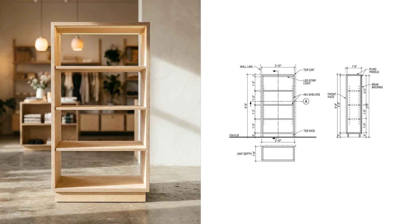
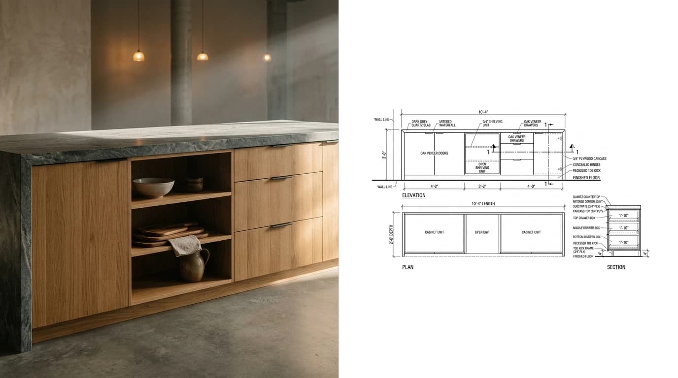
Getting from a physical object or a photograph to a dimensioned starting point. That covers real situations: matching existing millwork in a phased fit-out, replicating a prototype piece across a multi-site rollout, documenting legacy work with no surviving drawings, or turning a client's reference photo into something you can price. Upload the photo, anchor it to one real measurement you took, and you get orthographic views at true scale exported as DWG or DXF that you open and detail in your own template. That is what TechDraw AI does, and if AutoCAD is where you detail, the AutoCAD handoff is a DWG you simply open. The same approach applied to loose furniture is covered in furniture shop drawings from a photo.
What it does not do
Everything that makes it a millwork drawing rather than a picture of a cabinet. A photograph contains no information about substrate, edgebanding, blocking, hinge type, whether that panel is 3/4 inch ply or 1 inch MDF, or how the piece is fastened to the wall behind it. Those are engineering decisions that a detailer makes from the spec and the site, and they are precisely the decisions a reviewer scrutinises. Anything promising a complete submittal from an image is describing the easy half and skipping the half that gets rejected.
Pre-submittal checklist
- Cover, index and revision number present and current.
- Key plan ties every item to a room or grid location.
- Plans and elevations at 1/2 or 3/4 inch to the foot.
- At least one section per item type, at 1-1/2 or 3 inch.
- Details for every mitre, reveal, transition and lighting recess.
- Aesthetic grade and duty level stated.
- Hardware schedule with real model numbers.
- Finish schedule tied to the material callouts on the views.
- Field verification status noted explicitly.
- Scribes, fillers and hold dimensions drawn and dimensioned.
- Every deviation clouded and described in writing.
- Views and schedules cross-checked against each other.
On file formats, send what the reviewer asked for and keep your own working file separate. PDF for the submittal itself, DWG when the architect wants to overlay your work on theirs. DWG vs DXF covers which to send when the request is ambiguous, and CAD file formats for manufacturing covers what the shop floor downstream actually needs. The joinery specific version lives in AI technical drawings for furniture.
Frequently asked questions
What is a millwork shop drawing?
A millwork shop drawing is the fabrication document a millwork shop produces for custom interior woodwork: reception desks, casework, wall panelling, doors and trim. It translates the architect's design intent into exactly what will be built, showing plans, elevations, sections and details at fabrication scale, with materials, finishes, hardware and field-verified dimensions. It is submitted for review before anything is cut.
What is the difference between millwork and casework?
Casework is the box: standardised cabinet units, base and wall cabinets, built to repeatable sizes. Millwork is the broader category of custom-fabricated interior woodwork, which includes casework but also reception desks, wall panelling, running trim, custom doors and one-off feature pieces. In practice a single submittal often covers both, and ANSI/AWI 0641 is the casework standard specifically.
Who prepares millwork shop drawings?
The millwork subcontractor or fabricator, either with in-house detailers or an outsourced drafting service. The contractor then reviews and submits them to the architect. Under AIA A201 the act of submitting is itself a warranty by the contractor that it has reviewed the drawings and verified materials and field measurements, so it is not a pass-through step.
What scale are millwork shop drawings drawn at?
Plans and elevations are typically drawn at 1/2 inch or 3/4 inch to the foot so a whole run reads on one sheet, and sections and details are enlarged to 1-1/2 inch or 3 inch to the foot so panel thicknesses, reveals and joints are actually legible. A detail drawn too small is the most common reason a reviewer cannot confirm what was intended.
Does the architect's approval make the millwork shop's mistakes their problem?
No, and this is the most expensive misunderstanding in the process. Under AIA A201 the architect reviews submittals only for conformance with the design concept expressed in the contract documents. Approval does not relieve the contractor of responsibility for deviations unless the contractor gave specific written notice of that deviation and got written approval of it, and it does not relieve liability for errors or omissions in the submittal itself. An approved drawing with a wrong dimension is still your wrong dimension.
What is the difference between an AWI aesthetic grade and a duty level?
They are two separate specifications that used to be one. ANSI/AWI 0641, effective 1 June 2020, split them: aesthetic grade (Economy, Custom or Premium) covers appearance and workmanship on exposed and semi-exposed surfaces, while duty level (1 through 4) covers structural performance, derived from physical testing. Because they are independent, a project can specify a high aesthetic grade with a modest duty level, or the reverse. If your drawing names only a grade, half the specification is missing.
Can I make millwork shop drawings from a photo?
You can get a dimensioned starting point from a photo, which is genuinely useful when you are matching existing work, replicating a piece across a rollout or documenting something with no drawings. What a photo cannot give you is the hidden half: joinery, substrate, hardware, blocking and how the piece meets the wall. Those are engineering decisions, and they are also the parts a reviewer looks at hardest.
Sources
- AWI QCP: ANSI/AWI 0641 Architectural Wood Casework, aesthetic grades and duty levels explained
- Architectural Woodwork Institute: current ANSI/AWI standards
- IRMI: Design professional review of submittals under the AIA documents (A201 sections 3.12 and 4.2.7)
- EJCDC: Shop drawings and submittals, liability associated with submittal reviews
- CSI MasterFormat Division 06, Wood, Plastics and Composites