
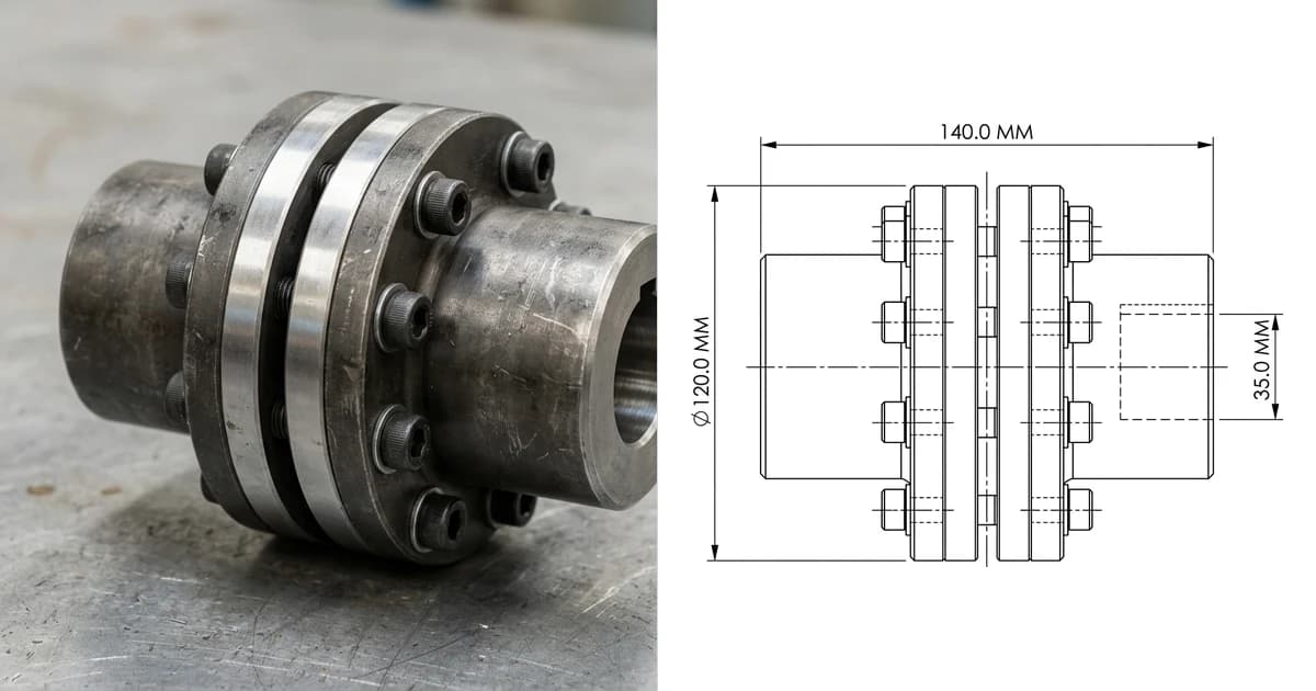
A detail drawing tells a shop how to make one part. It says nothing about which way round that part goes, what it bolts to, or what has to be in the box when it ships. That is a different drawing, it works by different rules, and the most common way to get it wrong is to treat it like a big detail drawing and cover it in dimensions.
Our articles are still written by humans!
Get human written articles in your Google feed.


The short answer
An assembly drawing shows how separate parts fit together to make a finished product. It identifies each component with a numbered balloon keyed to a parts list, shows the parts in their assembled positions or pulled apart in an exploded view, and dimensions only the assembly itself. ASME Y14.24 lists it as one of the formal types of engineering drawing, alongside the detail, installation and layout drawing.
If you want the wider picture of what any engineering drawing has to carry before you get to assemblies, that is the parent guide: engineering drawing, what has to be on the sheet.
What it adds to a part drawing
The easiest way to see the split is to notice what each drawing is allowed to say. A detail drawing owns every dimension of one part. An assembly drawing owns everything that only becomes true once the parts meet.
Who owns what, across the two drawings
That last row catches people out. An assembly is not finished when the parts are stacked; it is finished when the bolts are at the right torque, the right sealant is in the right joint and it has passed whatever check you require. None of that is geometry, so none of it can live anywhere but a note on this sheet.
The exploded view
An assembled view has a problem: the interesting parts are usually hidden inside it. The exploded view solves it by pulling every component apart along the axis it assembles on and drawing thin dashed lines to show the path each one travels back into place.
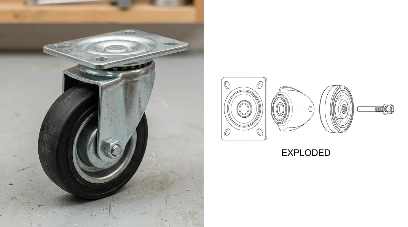
Two rules make an exploded view readable. Keep every part on a shared centre line wherever it physically shares an axis, because that line is what tells the reader these things go together rather than merely sit near each other. And explode along one direction at a time. A view that flies parts off in five directions looks impressive and communicates nothing.
Balloons and the parts list
A balloon is a small circle holding an item number, with a leader line touching the component it names. On its own it means nothing. Its whole job is to point at a row in the parts list, so item 3 in the table is the part the balloon marked 3 is touching.
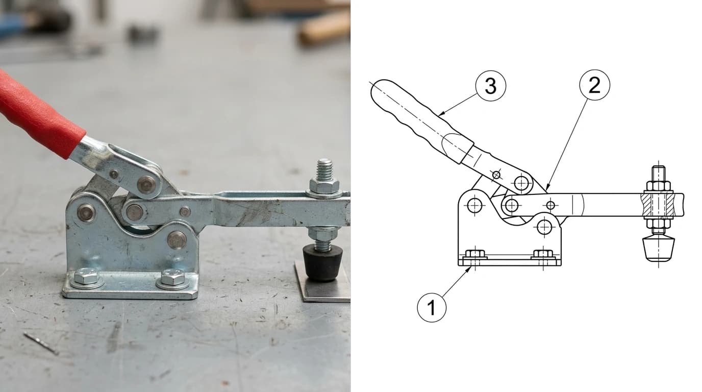
The parts list is the other half, and in US practice it has its own standard: ASME Y14.34, Associated Lists. Shops call it a parts list, an item list or a bill of materials fairly interchangeably. What matters is that each row carries the item number matching its balloon, the part number, a description, the quantity, and for bought-in items enough detail to order the right thing.
A few habits that save arguments. Number in assembly order where you can, so the list doubles as a build sequence. Use an item number once per drawing, even if the same part appears in three places, and let the quantity column carry the count. And put fasteners at the end of the list rather than scattered through it, so the person picking stock can see the whole hardware requirement in one block.
Sectioning through a joint
When the question is how two parts actually meet, no external view will answer it. Cut a section through the joint and the answer is obvious in one picture. The convention that makes an assembly section work is the hatching: each part gets its hatching at a different angle, so the eye separates one component from the next without needing a label.
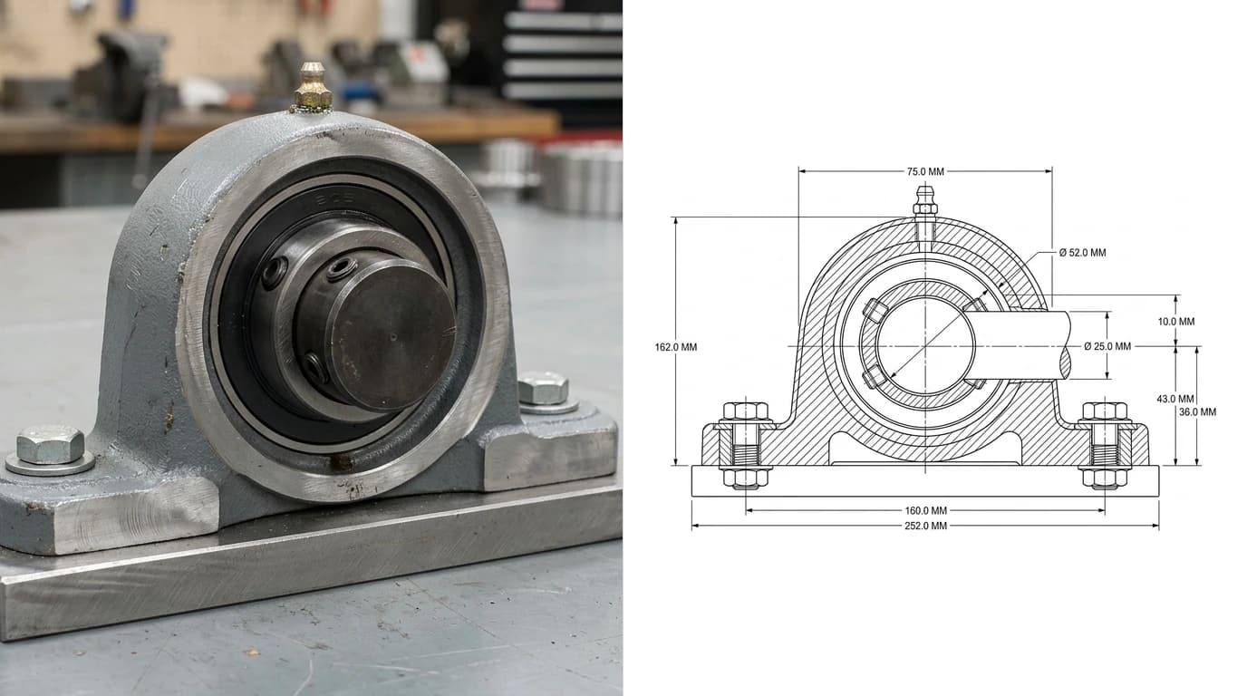
One more convention worth knowing, because it looks like an error until someone explains it: shafts, bolts, pins, keys, rivets and similar solid parts are not sectioned even when the cutting plane passes straight through them. Hatching a bolt tells the reader nothing about a bolt and makes the parts around it harder to read, so drafting practice leaves it drawn whole. If you want the rest of the line and section conventions, they sit in how to read a technical drawing.
Dimension the fit, not the parts
This is where most first assembly drawings go wrong, and the error feels like diligence. You have the numbers, so you write them on. But a dimension that already lives on a detail drawing must not be repeated here, because the moment there are two sources for one number they can disagree, and then nobody knows which one the part was made to.
What belongs here instead is the small set of dimensions that do not exist on any single part:
- Overall envelope. How much space the finished thing needs, which is what the person designing around it actually wants.
- Mounting centres and interface dimensions. Where the fixing holes are and what the mating face looks like, so somebody can bolt it to something.
- Travel, stroke or swing. Anything that moves needs its range dimensioned, plus the clearance it sweeps through.
- The fits that matter. Where a shaft goes into a bore, the important number is neither diameter alone, it is the clearance or interference between them. That relationship is an assembly property and this is the only drawing that can state it.
Fits have their own vocabulary, and if you are choosing one rather than recording it, the limits and their meaning are covered in how to read tolerances on a drawing.
General, sub and installation
Assembly drawings come in a small family, and the names describe how far up the tree the sheet sits.
- General assembly, usually shortened to GA. The top sheet: the whole product with its major sub-assemblies in place, overall dimensions, mounting information and the top-level parts list.
- Sub-assembly drawing. One module of the product, in the detail the GA has no room for. Its own parts list covers only its own contents, and it appears as a single item on the GA above it.
- Installation drawing. Not how the thing is built but how it is fitted where it goes: foundations, services, access clearance, and the dimensions the person on site needs.
ASME Y14.24treats this as its own type.
For work that arrives on a construction site rather than a bench, the equivalent document has a different name and a different contractual status, which we cover in shop drawings vs construction drawings.
Four mistakes that stall a build
- Dimensioning the parts all over again. Covered above, and it is the most common one by a distance. If the number is on a detail drawing, it does not belong here.
- Balloons that point at nothing in particular. A leader that stops in white space near a cluster of parts, or lands on a dimension line, forces the reader to guess. The arrowhead or dot touches the component, inside its outline.
- A parts list that does not match the balloons. Item 5 on the drawing and item 5 in the table being different things is usually the result of editing one and not the other. It is worth a deliberate check before release, because nothing downstream will catch it.
- No assembly notes. Torque values, thread locker, grease, seal orientation, run-in or test requirements. The assembler will do something in each of those cases whether you specified it or not.
Getting one made
If the product is still a design, the assembly drawing falls out of the CAD model, and the exploded view and parts list are largely automatic once the model is structured properly. The video above shows that route.
The harder case is the one that brings most people here: the assembly exists and the drawings do not. A machine that has to be maintained, a product being taken over from another supplier, a spare nobody has a file for. There the work starts with the object, and it goes in this order: photograph it assembled, take it apart in a recorded sequence, measure each part properly, then draw the assembly back up from what you found. Our guides on reverse engineering a part and measuring a part cover the middle two steps, which are the ones that decide whether the drawing is any good.
For the drawing itself, our AI technical drawing generator works from a photograph and returns dimensioned views exported as DXF, DWG and PDF, which is a fast way to get the views and the arrangement on paper. Be clear about what that can and cannot do, because it matters more on an assembly than on a single part: a photograph shows the outside, so the views, the arrangement and the balloons come straight from it, but anything inside the assembly has to come from taking it apart, and the real numbers still come from your calipers. What you save is the drafting. The measuring and the specifying are still yours.
The bottom line
An assembly drawing is a different document from a part drawing, not a bigger one. It names the parts, shows where they go and in what order, and dimensions only what the parts cannot say alone. Balloon every component, keep the parts list honest against those balloons, hatch each part at its own angle when you cut through, and resist writing a number that already exists somewhere else. Do that and the person building it never has to phone you.
Frequently asked questions
What is an assembly drawing?
An assembly drawing is an engineering drawing that shows how separate parts fit together to make a finished product. Instead of dimensioning every feature, it identifies each component with a balloon and a parts list, shows the parts in their assembled positions, and carries only the dimensions that describe the assembly itself: overall size, mounting centres, travel and the fits between mating parts. ASME Y14.24 defines it as one of the formal types of engineering drawing.
What is the difference between an assembly drawing and a detail drawing?
A detail drawing documents one part completely, with every dimension, tolerance, material and finish needed to make it. An assembly drawing documents the relationship between parts: what goes where, in what order, and how they fit. A detail drawing answers how do I make this part; an assembly drawing answers how do these parts go together. Most products need both, and the assembly drawing is what carries the parts list.
What is an exploded view?
An exploded view draws each component pulled apart from the others along the axis it assembles on, with thin dashed lines showing the path each part travels back into place. It is used when the assembled view hides parts inside, which is most of the time. It is the clearest way to show assembly order and is standard in service manuals and spare-parts documentation.
What are balloons on an assembly drawing?
Balloons are small circles containing an item number, each with a leader line touching one component. They connect the picture to the parts list, so item 3 in the table is the part the balloon marked 3 points at. Each item number is used once per drawing, and the numbers usually run in assembly order or in order around the view rather than at random.
Does an assembly drawing need dimensions?
Only a few, and they are a different kind. An assembly drawing should not repeat the dimensions already on the detail drawings, because two sources for one number is how parts get made to the wrong one. It carries the dimensions that only exist once the parts are together: overall envelope, mounting hole centres, stroke or travel, shaft height, and any critical clearance or interference between mating parts.
What is a general assembly drawing?
A general assembly, often shortened to GA, shows the complete product with all its major sub-assemblies in place and is the top sheet of a drawing set. Below it sit sub-assembly drawings covering one module each, and below those the detail drawings for individual parts. The GA carries the overall dimensions, the mounting information and the top-level parts list.
What is the parts list on an assembly drawing called?
It is called a parts list, an item list, or a bill of materials (BOM); the terms are used interchangeably in most shops. In US practice these are covered by ASME Y14.34, Associated Lists. At minimum each row carries the item number that matches its balloon, the part number, a description, the quantity and often the material or a supplier reference for bought-in items.
Can you make an assembly drawing from a photo?
Partly. A photograph of an assembled item fixes the arrangement, the proportions and the visible components, which is enough to produce the views, the exploded arrangement and the balloons. What a photograph cannot give you is what is inside the assembly or the real dimensions, so internal parts have to be established by taking the item apart and measuring, and the numbers have to come from calipers or a known reference in frame.
Sources
- ASME Y14.24-2020: Types and Applications of Engineering Drawings, which defines assembly, detail, installation and layout drawings
- ASME Y14.34: Associated Lists, the US standard covering parts lists, bills of materials and data lists
- ASME Y14.100-2017: Engineering Drawing Practices, the master US drawing-practices standard
- ISO 128-3: Technical product documentation, general principles of representation, views, sections and cuts
- ISO 7200:2004: Technical product documentation, data fields in title blocks and document headers