It is easy to claim AI can draw. It is more useful to show it. So we took three real parts anyone can buy, ran each through the exact pipeline behind TechDraw AI, and graded the result like a drawing checker would — looking just as hard for what it got wrong as for what it got right. Here is the honest scorecard.
How we made these
No trickery, and the same flow a user follows in the app. For each part we started from one clean photo, told the tool one real measurement to fix the scale, and let it generate a standards-style drawing. Under the hood that photo and a detailed drafting prompt go to an image-capable model with a single instruction — be an expert mechanical drafter and return a flat, monochrome, dimensioned orthographic drawing, nothing else.
That last point matters and it is the honest framing for this whole post: the output is an AI-generated drawing, not geometry computed from a 3D model. It is fast and it looks right, which is exactly why you have to check it rather than trust it. Two things the photo physically cannot supply, and which we had to provide, are the true scale — covered in getting dimensions from a photo — and the design intent, the theme of what AI can actually do from a photo.
Part 1: a 608 skate bearing
The classic 608: a deep-groove ball bearing, ⌀22 outer, ⌀8 bore, 7 mm wide. A round, turned part is a good first test because it forces the model to think in a front view plus a section, not just an outline.
 Photo
Photo Drawing
What it nailed: the ⌀22 outer diameter and the 7 mm width are dimensioned correctly with the ⌀ prefix; the section view actually shows the ball track through the races, which is how a bearing should be drawn; and it added a general tolerance note in proper ISO style.
What needs you: the ⌀8 bore is the dimension you most want and it is the one drawn least clearly. And the model could not resist a full material spec — hardened-steel races, silicon-nitride ceramic balls, even a named grease. It cannot know any of that from a photo. It is plausible, it is professionally worded, and it is invented. Treat those callouts as a checklist to fill in, not facts.
Part 2: a steel angle bracket
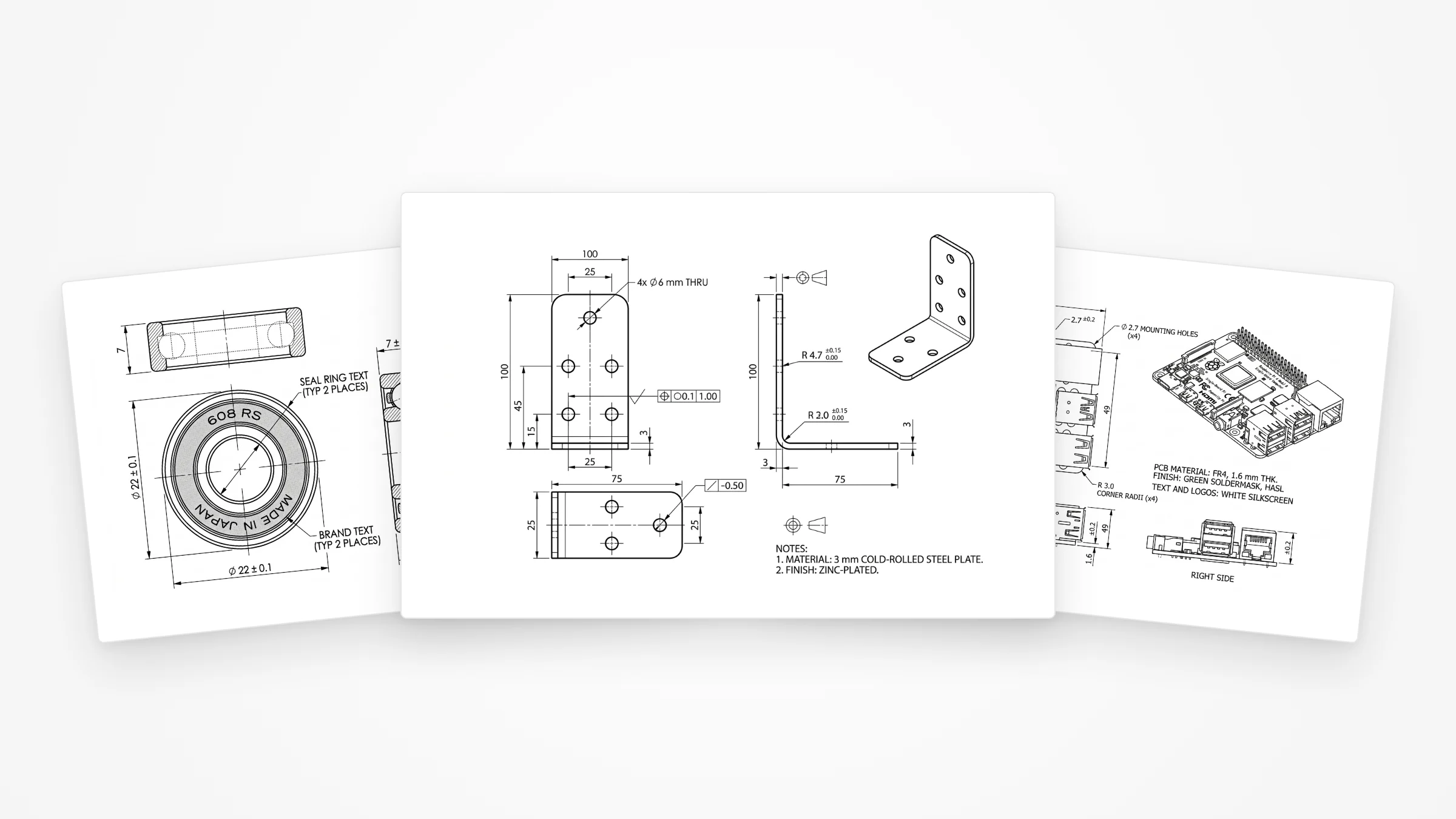
A bent steel L-bracket with mounting holes — the bread and butter of sheet-metal and fabrication work, and the kind of part people most often photograph instead of modelling. We gave it the two leg lengths, the width and the 3 mm thickness.
 Photo
Photo Drawing
What it nailed:this is the most complete of the three. Front, side and isometric views; the L-profile with the 3 mm thickness; a proper grouped hole callout; even geometric tolerance frames and a “3 mm cold-rolled steel, zinc-plated” material note. It reads like something a junior drafter would hand you.
What needs you:count the holes. The drawing's hole layout drifts from the photo, the bend radii are values the model chose, and the GD&T is decorative — sensible-looking frames with numbers nobody specified. The skeleton is right; every functional value is yours to set and verify against the part. This is exactly the line we draw in what makes a drawing manufacturing-ready.
Part 3: a single-board computer
The hardest and most revealing test: a Raspberry Pi board. It is a flat plate, so the geometry is simple, but it is a known part with a published mechanical drawing — which means we can check the AI against ground truth instead of vibes.
 Photo
Photo Drawing
What it nailed: the numbers. An 85 × 56 mm board, the 58 × 49 mm mounting-hole pattern set 3.5 mm from the edges, ⌀2.7 holes, R3 corners and the 1.6 mm board thickness in the side views. Compare that against the official Raspberry Pi mechanical drawing and it is essentially correct — the exact pattern you would build a case or a HAT against, recovered from a single photo.
What needs you:zoom into the board face. The silkscreen text is pure AI gibberish — “Poprerity Pi,” garbled chip codes, nonsense labels. It is the perfect demonstration of where to look and where to relax: the mechanical outline and hole pattern, the part you actually manufacture to, are right; the cosmetic text is noise you ignore or delete.
What AI nailed — and what still needs you
Across all three, the same pattern. AI is now genuinely strong at the mechanical drafter's first eighty percent: choosing the right views, projecting the geometry faithfully, placing dimension lines, applying ⌀ and R, and dropping in a sensible tolerance block — in seconds, from a photo, with no CAD seat. A year ago that was a person's afternoon.
The remaining twenty percent is the judgment a photograph cannot carry:
- True scale. A photo is dimensionless until you anchor it; one measured reference fixes the whole drawing, and the model fills the rest in proportionally.
- Design intent. Which tolerances are critical, whether a hole is a clearance or a press fit, what the thread actually is — that lives in your head, not in the silhouette.
- A hallucination pass. AI volunteers confident, professional-sounding detail it cannot know. The materials, the grease, the bend radii, the silkscreen. Read every callout and keep only what you specified or verified.
Want to run your own part? Drop a photo into our image to DXF converter, give it one real measurement, and you will get a drawing like these in seconds — then do the twenty percent only you can. If you are new to reading the result, start with how to read a technical drawing.
Frequently asked questions
Are AI-generated technical drawings accurate?
The geometry and the drafting are genuinely good: correct orthographic views, dimension lines with arrowheads, ⌀ and R prefixes, a sensible tolerance block and projection symbol. What AI cannot get from a photo is absolute scale (you anchor that with one real measurement) or design intent (which tolerances are critical, what the threads are). It also tends to volunteer confident-looking detail that is invented. So: production-shaped, but always proofread before you cut metal.
Can AI really make a technical drawing from a single photo?
Yes — for the views and the dimensioning. In our test, one clean photo of each part plus a couple of measurements produced fully laid-out orthographic drawings in seconds. The single photo cannot reveal true size on its own, so you give it one known dimension and the rest scales from there. Hidden internal features and exact thread specs still need a human or a second view.
Can I trust the dimensions an AI puts on a drawing?
Trust the ones you anchored to a real measurement, and treat everything else as a proposal. In our examples the model added a specific bearing grease, a ceramic ball material and a couple of bend radii that it had no way of knowing — all plausible, all invented. Confirm the dimensions that matter and delete the callouts you did not specify.
Which parts work best for AI technical drawings?
Single, rigid parts with clear external geometry: turned parts, brackets, plates, sheet-metal profiles, housings. The more the shape is readable straight-on, the better the drawing. Parts that depend on hidden bores, internal features, fine threads or organic freeform surfaces are where AI struggles and a human (or a scan) earns its keep.
Can a machine shop use an AI-generated drawing?
Shops care about the content, not who drew it. If the views are correct, the dimensions are right, the tolerances are stated and the title block is complete, it quotes and machines like any other drawing. The job before you send it is to confirm the critical dimensions and strip anything the AI invented.