
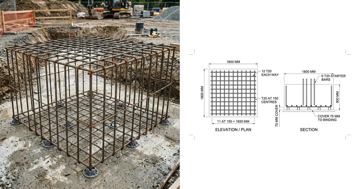
Rebar shop drawings are the reinforcement fabricator's submittal for a concrete structure, and the thing most explanations skate over is that they are two documents, not one. A placing drawing says where every bar sits. A bar bending schedule says how every bar is cut and bent. They are issued together, they are tied to each other by bar mark, and they fail in different ways.
Our articles are still written by humans!
Get human written articles in your Google feed.
The short answer
A structural engineer's drawings say what the concrete has to do: this beam spans here, it carries this, it needs this much steel. They do not say that bar number 14 is a T20 bent to shape with legs of 1200 and 400, that there are twelve of them, and that they lap the column starters by 900. Somebody has to work that out, and the document they produce is the rebar shop drawing.
It is a submittal in the ordinary sense: prepared after the contract by the party who will supply the steel, issued for the engineer to review, and released to the yard once the review comes back clean. If the submittal process itself is unfamiliar, what are shop drawings covers the review loop and the stamps, and shop drawings vs construction drawings covers why an approved submittal still cannot change the contract.
Two documents, not one
This is the distinction worth carrying, because the two halves are checked by different people, fail in different ways, and only one of them gets looked at again after approval.
The two halves of a rebar submittal
The two are joined by the bar mark: a unique reference for every distinct bar in the job. A bar drawn on the placing drawing, listed in the schedule, tagged on a bundle in the yard and fixed in the formwork are all provably the same bar because they carry the same mark. Break that chain and everything downstream still looks orderly while being wrong.
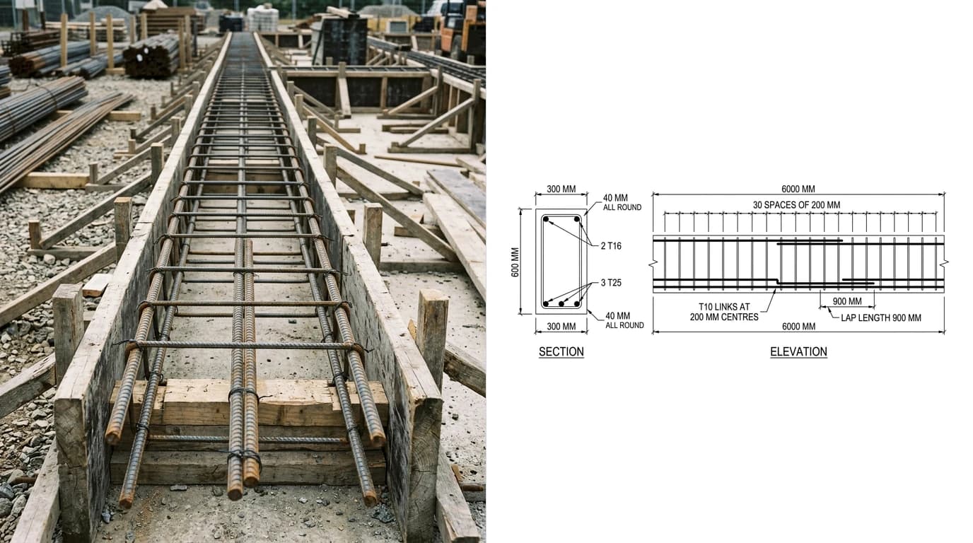
What is on a placing drawing
A placing drawing is not a general arrangement with some bars drawn on it. It is a drawing whose subject is the steel, so the concrete is drawn thin and the reinforcement thick, which is the opposite of an architectural convention and the first thing that looks strange if you have not read one before.
- Bar marks and quantities against every set of bars, normally as a count, a bar type letter and a diameter, such as
12 T20. - Spacing where bars repeat, given as centres, for example
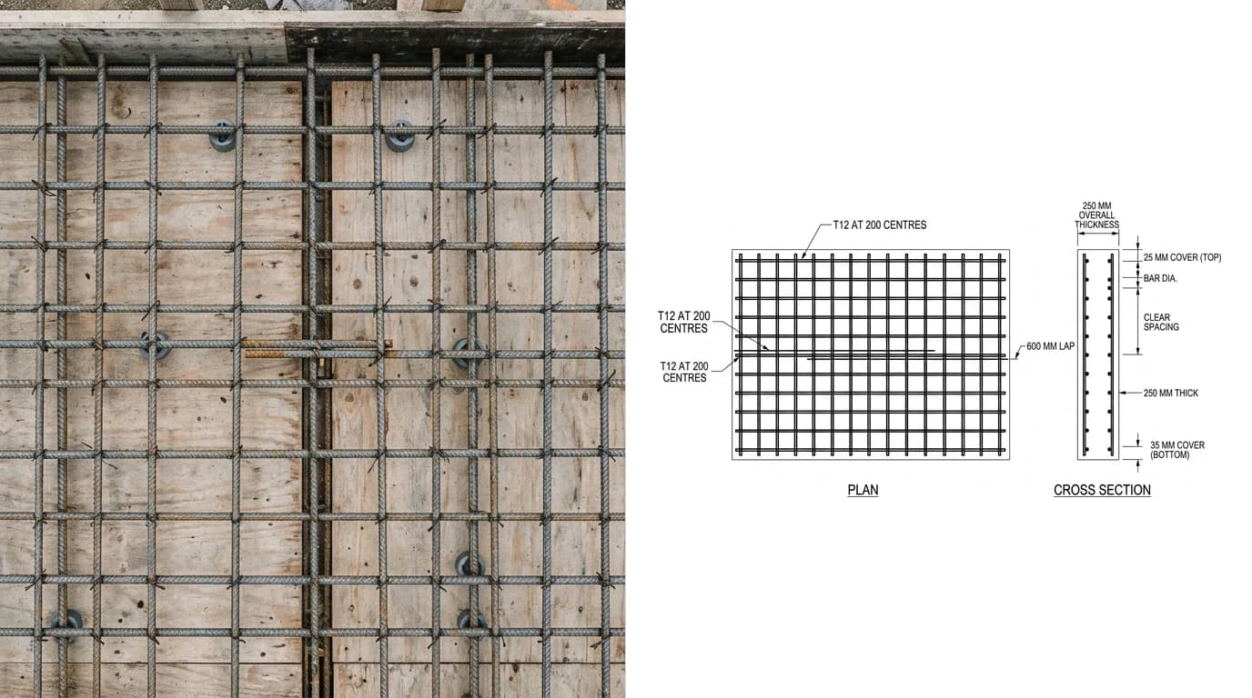
T10 AT 200 CENTRES. - Cover, the distance from the face of the concrete to the nearest steel. It comes from the specification and the exposure class, never from scaling the drawing.
- Laps and anchorage, where bars overlap to transfer force, dimensioned rather than left to the fixer.
- Sections through every member type, because a plan alone cannot show which layer sits above which.
What is in a bar bending schedule
The schedule is a table, and it is worth showing as one rather than describing. Each row is a complete instruction to cut and bend a batch of identical bars.
An illustrative bar bending schedule extract, laid out the way BS 8666 does. The bars are the beam above; the figures show the shape of a schedule rather than one to build from
Two columns in that table do the work people underestimate. The length is the cut length of the straight bar before bending, not the sum of the legs, because bending consumes material at every bend and the standard sets the allowance. And the shape code names the geometry so the legs can be given as plain letters. Get either wrong and the bar is manufactured confidently to the wrong size.
The codes in that extract are BS 8666 codes: 00 for the straight main bars, 44 for the closed link, 11 for the single-bend starter. Take the numbers as an illustration of the format rather than as values to schedule from, and take the codes from the current edition of whichever standard your project sits under, because they are not the same everywhere.
Shape codes
A shape code is a standardised number naming the geometry of a bent bar, so a schedule can specify the shape without drawing it. In BS 8666 the codes run from 00 to 99. Code 00 is a straight bar. Code 99 is the escape hatch: a special shape that no standard code fits, which must be drawn out in full on the schedule.
Each standard shape has its legs lettered in sequence, A, B, C and so on, and the schedule gives the length of each lettered leg for that mark. Some dimensions in the standard's shape drawings are shown in brackets, which marks them as free: the detailer chooses them so the legs and the overall cut length reconcile.
Worth saying plainly, because it catches people moving between markets: the shape code numbers are not international. A code that means one bend in a British schedule does not carry to an American one, and the bending allowances differ too. The idea travels; the numbers do not.
Who prepares them, who approves
The reinforcement supplier, or a specialist rebar detailing bureau working for them, prepares the drawings and the schedule from the structural engineer's design drawings. The engineer reviews them for conformance with the design and does not prepare them. Detailing is heavily outsourced as a trade, and a large share of the world's rebar detailing is done by dedicated firms in India and the Middle East detailing to whichever national standard the project sits under.
The practical consequence of that split is worth internalising. The detailer knows the standard and the fabrication constraints but has never seen the site. The engineer knows the design intent but is reviewing for conformance, not re-doing the arithmetic. Neither is checking whether the steel can physically be threaded into the formwork in the sequence the programme assumes. That gap is where congestion problems live.
How they get checked
Reviewers work through the same list, and it is short enough to use as your own before submitting.
- Do the marks reconcile? Every mark on the drawing appears in the schedule and the other way round, with the same quantity. This is the single most common defect and the quickest to find.
- Are the laps right? Lap length comes from the specification and the concrete grade, not from what fitted on the sheet.
- Is the cover specified rather than inherited? Different faces of the same member often have different cover, and the exposure class drives it.
- Do the legs and the cut length agree? The cut length has to account for the bending allowance, so it is not simply the sum of the legs.
- Does it build? At a beam-to-column junction, count what actually passes through. Congestion is the classic failure because it is invisible in two dimensions.
The habit that catches most of it is the same one that catches errors in any submittal: add the chain up. A spacing chain along a member has to total the member, and a schedule quantity has to match the count on the drawing. The wider version of this checklist is in what makes a drawing manufacturing-ready, and the trade-by-trade view is in structural steel shop drawings for the steel frame the concrete usually meets.
Which standard applies where
Rebar scheduling standards by market
Whichever applies, the obligation is the same one every submittal carries: the drawing and the schedule have to say which standard they were prepared to, because a schedule read against the wrong standard is a schedule read wrongly.
Where the pictures came from
The bar shapes above are drawn as vector graphics, and labelled by geometry rather than by code number on purpose: published shape code tables disagree with each other, and inventing a number would be worse than useless to the one reader who trusts it. The photographs and the drawings beside them are real output from our own pipeline, a photograph in and a dimensioned drawing out. That is what TechDraw AI does, and the honest limit is the one every photo-based tool shares: a picture gives shape and proportion, and a person still supplies the scale, the cover and the standard. The route is in image to DWG, and getting dimensions from a photo explains why the reference measurement matters.
Watch: Reading a set of rebar shop drawings
Plan and Spec made a long walkthrough of the rebar shop drawing process from the American side of the trade. By its own chapter list it covers where rebar shop drawings sit in the concrete submittal requirements, who fixes the steel, rebar grades 40, 60 and 75, bar sizing, coatings and accessories, and then spends everything from about the six minute mark on reading a set of the drawings. It is worth the time if the placing drawing section above was your first look at one. It works in US practice, so take shape codes and bending allowances from whichever standard your project names, as the standards table says.
Frequently asked questions
What are rebar shop drawings?
Rebar shop drawings are the reinforcement fabricator's submittal for a concrete structure, and they come as two linked documents. The placing drawing shows where every bar sits inside the concrete, with bar marks, spacings, laps and cover. The bar bending schedule is a table listing every bar mark with its diameter, shape code, cut length, bending dimensions and quantity. The drawing tells the steel fixer what to build; the schedule tells the fabricator what to cut and bend.
What is the difference between a placing drawing and a bar bending schedule?
A placing drawing is a drawing and a bar bending schedule is a table, and they answer different questions. The placing drawing answers where each bar goes and how far apart, working from the engineer's structural drawings. The schedule answers how each bar is cut and bent, in a row per bar mark that a cut-and-bend machine can read. They are issued together and cross-referenced by bar mark, which is why an error in the mark on one is invisible until steel arrives on site.
Who prepares rebar shop drawings?
The reinforcement supplier or a specialist rebar detailing bureau, working from the structural engineer's design drawings. The engineer does not prepare them; the engineer reviews them for conformance with the design. Detailing is often outsourced, and a large share of the world's rebar detailing is done by dedicated firms in India and the Middle East working to the standard of whichever country the project sits in.
What is a bar mark?
A bar mark is the unique reference given to every distinct bar in a job, so that a bar drawn on a placing drawing, listed on a schedule, tagged on a bundle in the yard and fixed on site are all provably the same bar. A typical mark reads as a quantity, a bar type letter and a diameter, such as 12 T20, and the schedule then carries the shape code and the bending dimensions for that mark.
What is a shape code in a bar bending schedule?
A shape code is a standardised number that names the geometry of a bent bar, so the schedule can specify the shape without drawing it. BS 8666 uses codes from 00 to 99, where 00 is a straight bar and 99 is a special shape that must be drawn out because no standard code fits it. Each shape has lettered legs, A, B, C and so on, and the schedule gives the length of each leg for that particular bar mark.
Why do rebar shop drawings get rejected?
Most rejections are traceable rather than conceptual: bar marks on the drawing that do not match the schedule, laps shorter than the specification allows, cover taken from the design drawing rather than the specification, bars that clash where two members meet, and cut lengths that ignore the bending allowance so the bent bar comes out short. Congestion at beam and column junctions is the classic one, because it looks fine in two dimensions and cannot be built in three.
Can you fabricate rebar directly from the schedule?
Yes, and that is precisely why the schedule carries the risk. Bar bending schedules are routinely fed straight into CNC cut-and-bend machinery, so a wrong number in a schedule row becomes several tonnes of physically wrong steel without a human reading it in between. The placing drawing gets checked by eye on site; the schedule often does not get checked by anyone after approval.
What standard applies to bar bending schedules?
It depends on the market. BS 8666, currently the 2020 edition, is the specification for scheduling, dimensioning, bending and cutting steel reinforcement in the United Kingdom and much of the Commonwealth, and it defines the shape codes. In the United States the equivalent practice comes from the ACI detailing manual and the CRSI Manual of Standard Practice, and Canada follows ACI with RSIC. The concepts carry across; the shape code numbers and bending allowances do not.