
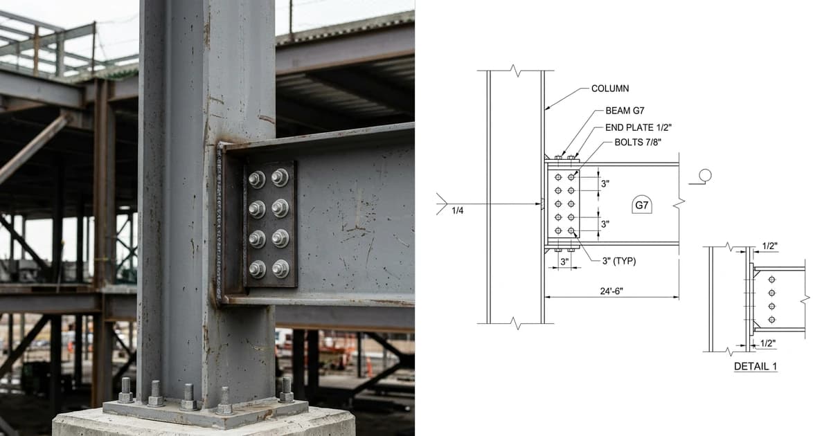
Most steel submittals that come back marked up are not wrong about the steel. The beam really is a W18x35, the plate really is half an inch. What sinks them is smaller and more expensive: a mark that appears twice, a connection nobody was told to design, or a set that came back approved and left the fabricator holding a dimension he never checked. This is what a structural steel shop drawing has to carry, and what the code actually says an approval buys you.
Our articles are still written by humans!
Get human written articles in your Google feed.
What a steel shop drawing is
Ask five people on a project what a steel shop drawing is and you get five answers, most of them describing a picture of part of the building. The code is narrower than that, and the narrowness is the point. ANSI/AISC 303-22 defines shop drawings in its glossary as drawings of the individual structural steel shipping pieces that are to be produced in the fabrication shop.
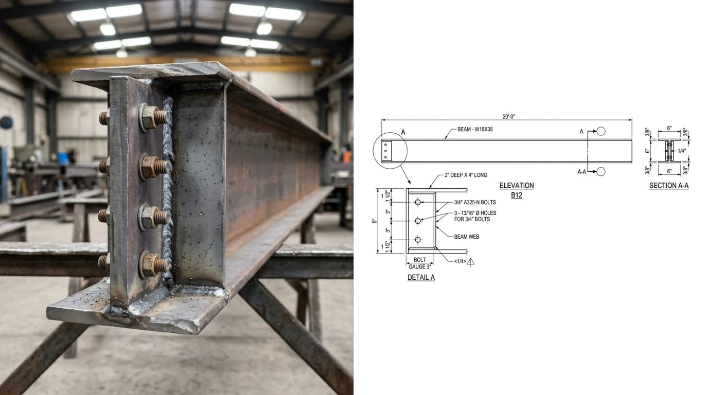
Read that again with the emphasis on shipping pieces. A shop drawing is not a drawing of a frame, a bay or a connection. It is a drawing of the thing that will be lifted onto a truck: this beam, this column, this brace, with everything that has to be done to it before it leaves. Length, copes, holes, welded attachments, material grade, finish, and the mark that will be painted on it. If a piece of information does not belong to that one physical object, it belongs on a different sheet.
That definition is doing real work. It is why a shop drawing shows a beam with its connection plates already attached but not the column they will bolt to. It is why the shop can fabricate from the sheet without knowing which grid line the piece lands on. And it is why the general bar any fabrication drawing has to clear, covered in what makes a drawing manufacturing-ready, applies here with one addition: a steel piece also has to be findable again after it is made.
Shop, erection and the third set
Steel work generates at least three kinds of drawing and they are routinely conflated in conversation, in specifications and in requests for quotation. The distinctions are all in the AISC 303 glossary.
The three drawing types AISC 303-22 distinguishes, and who each one is actually for
The pairing that matters day to day is the first two. Shop drawings are the individual shipping pieces produced in the shop. Erection drawings, in the code's words, are field-installation or member-placement drawings showing the location and attachment of the individual shipping pieces. One is a manufacturing instruction, the other is an assembly instruction, and they are almost never useful to the same person on the same day.
The third set catches people out. Erection bracing drawings are prepared by the erector, not the detailer, and they illustrate the sequence of erection, any requirements for temporary supports and the requirements for raising, bolting and welding. The code is explicit that these are in addition to the erection drawings. If your subcontract quietly assumes the detailer will produce them, someone is going to be surprised.
If the wider question is which of these documents is contractual at all, that is the subject of shop drawings vs construction drawings vs as-builts, which places the submittal chain against the contract documents.

The piece mark is the drawing
Here is the sentence worth taking away from this article. The piece mark is the only thing that connects the drawing that says how to make the steel, the drawing that says where it goes, and the steel itself. Everything else on the sheet can be re-derived. A mark cannot.
A piece of steel leaves the shop with a mark painted or stamped on it. Weeks later it is one of four hundred pieces in a laydown yard, in the rain, and an ironworker with an erection drawing has to find it. At that moment the mark is the entire information system. Three failure modes follow, and all of them are cheap to prevent and expensive to discover.
- The duplicate. Two genuinely different pieces carry the same mark, usually because a revision changed one of them and the mark was not advanced. The shop makes two of the wrong one.
- The orphan. The erection drawing calls for a mark that exists in no shop drawing. Nobody notices until the piece is missing from the delivery.
- The near miss. Marks that differ by one character in a font where the characters look alike. This is why detailers avoid combinations that read the same at ten feet in bad light.
The discipline is boring and it works: one mark per distinct piece, advance the mark whenever the geometry changes rather than reusing it, and cross-check the mark list in the erection set against the mark list in the shop set before issuing. Handedness deserves its own note. A piece and its mirror image are two different pieces and need two different marks, no matter how tempting it is to draw one and write “opposite hand” beside it.
Who designs the connection
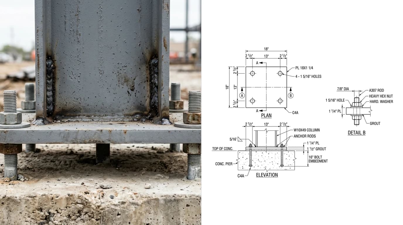
This is the single most argued question in steel, and the code answers it with unusual directness. AISC 303-22 Section 3.2.3requires the owner's designated representative for design to indicate one of three options for each connection. Not for the project. For each connection.
The three connection options in AISC 303-22 Section 3.2.3
Option 3 is where the money and the risk live, and it carries requirements the other two do not. Substantiating connection information has to be provided. The fabricator has to submit representative samples of that information for all connection types early, and the engineer has to confirm in writing that they comply or say what has to change, and the code is explicit that this initial round is in addition to the normal approval process. The licensed engineer in responsible charge of the connection design also has to review and confirm in writing that the approval documents properly incorporate the connection designs, and that review does notreplace the engineer's own approval.
Where Option 2 or Option 3 is specified, the code also lists what the engineer must hand over: project-specific connection details showing the conceptual configuration, any restrictions on connection types, the loads including shears, moments, axial forces and transfer forces, and crucially whether the forces are given at service-load or factored-load level and whether LRFD or ASD is to be used. A set of forces with no statement of which level they are at is not usable, and asking is not pedantry.
What approval does not do
The folklore is that once the set comes back stamped, the risk has moved. It has not, and Section 4.4.1 is one of the clearest paragraphs in the whole code about it.
Approval, approval subject to corrections noted and similar approvals constitute exactly three things:
- Confirmation that the fabricator has correctly interpreted the contract documents in preparing the submittal.
- Confirmation that the engineer has reviewed and approved the connection details shown.
- Release to begin fabrication using the approved submittals.
And then the sentence that should be pinned above every detailer's desk: such approval shall not relieve the fabricator of the responsibility for either the accuracy of the detailed dimensions in the approval documents or the general fit-up of parts that are to be assembled in the field.
Read plainly, the engineer is confirming that you understood the design and that the connections are acceptable. The engineer is not confirming that your dimensions add up or that your pieces will fit together. Those stayed with you the whole time. Three habits follow, and they cost nothing.
- Check dimension chains before issue, not after approval. Every chain of spacings must total the overall above it. This is the one class of error an approval will never catch for you, because the reviewer is reading intent, not doing arithmetic.
- Flag every deviation in writing, on the sheet. A clouded, noted and transmitted change is a negotiation. The same change absorbed quietly into a nicely drawn elevation is your cost when it surfaces.
- Treat “approved subject to corrections noted” as work, not as a pass.The code requires the fabricator to make the noted corrections and furnish corrected documents. Whether they come back for record is the engineer's call, but making them is not optional.
On timing, the commentary explains that the 14-day allotment for returning approval documents represents portal-to-portal time and may be assumed in the absence of contrary information for bidding and scheduling. If you are submitting substantiating connection information under Option 3, the commentary itself suggests specifying a longer allotment in the contract rather than discovering the problem in the programme.
The 2022 change nobody reads
ANSI/AISC 303-22 was released in November 2022 and supersedes ANSI/AISC 303-16. If your specification template still cites the 2016 edition, it is citing a superseded document, and the change is not only editorial.
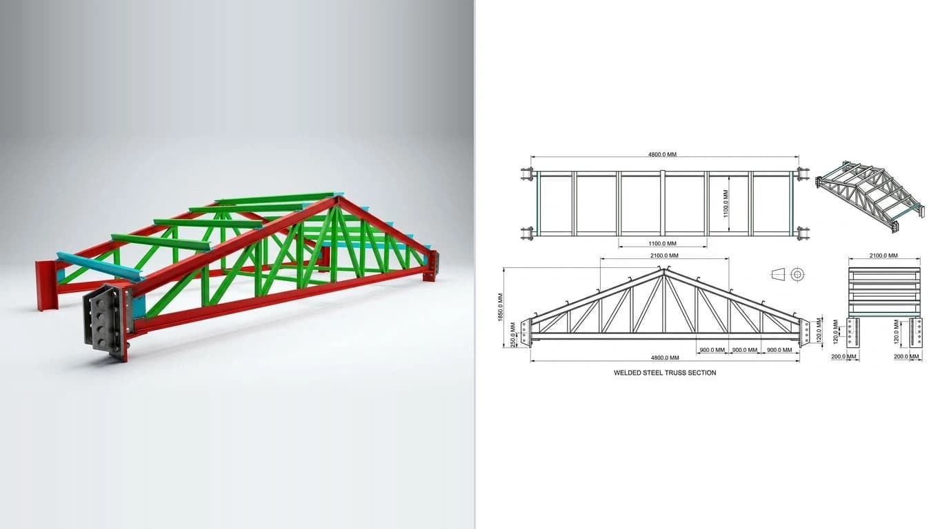
The vocabulary moved. The 2022 code talks about approval documents, fabrication documents and erection documents, and defines erection documents as erection drawings, an erection model, or a combination of the two. There is a glossary entry for an erection model as a three-dimensional digital model produced to convey the information necessary to erect the steel, which may or may not be the same model as the fabrication model.
The practical consequence is that on a modern project the deliverable being approved may not be a set of sheets at all, and the contract needs to say which it is. Two questions worth settling before the first submittal: is the approved deliverable the drawings, the model, or both, and if a model, what happens when the model and a sheet disagree. Those are cheap conversations in week one and expensive ones in month six.
What gets a set sent back
Ranked by how often it happens rather than how serious it is:
- Dimension chains that do not add up.The individual spacings and the overall disagree. Nothing destroys a reviewer's confidence in a set faster, because it is checkable in seconds.
- Duplicate or missing piece marks between the shop set and the erection set.
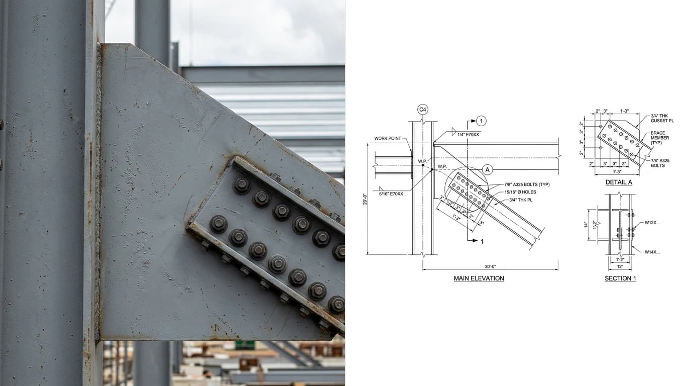
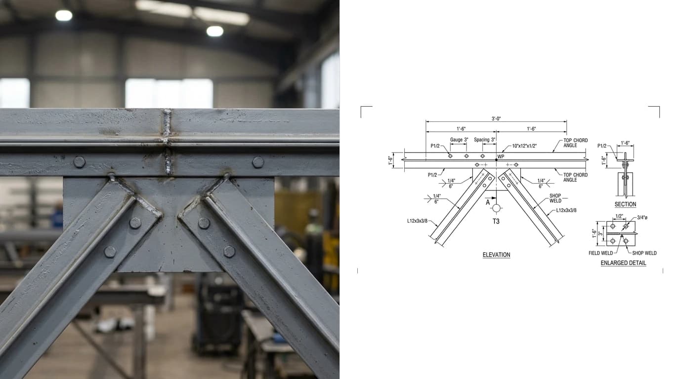
- No work point shown on a braced or moment connection, leaving the geometry unanchored.
- Connections detailed under the wrong option, most often a detailer completing a connection that the documents delegated to a licensed engineer under Option 3.
- Forces used at the wrong level, service versus factored, because the design documents did not say and nobody asked.
- Material grade missing from a plate or a shape. A size is not a specification.
- Welds described in words instead of drawn as symbols with a size and a length.
- Hole sizes not stated, or standard holes assumed where the design intended short slots for erection tolerance.
- Copes and blocks undimensioned, which the shop then resolves with a grinder.
- Revisions not clouded, so the reviewer has to re-read the whole sheet to find what moved.
Most of these are drafting discipline rather than engineering, and if your team is inconsistent about the conventions themselves, the guide to dimensioning a technical drawing covers what is worth standardising across a shop.
Where AI fits, honestly
There is a narrow place where AI genuinely saves a steel detailer time, and a much larger place where it does not. Being straight about the boundary is more useful than a pitch.
What it does well
Getting from a physical piece of steel or a photograph to a dimensioned starting point. That is real work in steel, and it is almost always retrofit work: an existing member you have to match in a strengthening job, a bracket on a plant item with no surviving drawing, a corroded connection being replaced like for like, a survey of existing steelwork before a change of use. You photograph the piece, anchor the image to one measurement you actually took, and get orthographic views at true scale that you export as DWG or DXF and open in your own template. That is what TechDraw AI does. If AutoCAD is where you detail, the AutoCAD handoff is a DWG you simply open, and how to measure a part covers taking the reference dimension properly. For pieces where the original drawing is genuinely gone, reverse engineering a part and obsolete machine parts walk the same process on machinery. Cutting the profiles afterwards is covered in DXF for plasma cutting.
What it does not do
Everything that makes it a steel drawing rather than a picture of a beam. A photograph carries no information about material grade, bolt grade or pretension requirement, weld procedure, the forces the connection has to carry, the erection sequence, or which of the three connection options applies. It cannot design a connection, and under Option 3 the code requires a licensed engineer to do that and to confirm in writing that the drawings incorporate it. Nor can it invent a piece mark that is unique across a set it has never seen.
Pre-submittal checklist
- Every dimension chain totals the overall dimension above it.
- One unique piece mark per distinct piece, opposite hands marked separately.
- Mark list in the erection set reconciled against the shop set.
- Work point shown and dimensioned on every braced and moment connection.
- Connection option identified for every connection type in the package.
- Force level stated as service or factored, and LRFD or ASD confirmed.
- Material grade against every shape, plate and bolt.
- Welds shown as symbols with size and length, never as sentences.
- Hole sizes and hole types stated, slots called out where intended.
- Copes, blocks and cuts dimensioned rather than left to the shop.
- Substantiating connection information referenced to its connections, under Option 3.
- Every deviation from the contract documents clouded and transmitted in writing.
- Revision clouds and revision numbers current on every changed sheet.
- Whether the approved deliverable is drawings, a model or both, agreed in writing.
On file formats, issue what the contract asked for and keep the working file separate. PDF for the submittal itself, DWG when the design team wants to overlay your steel on their layout, and a cutting format for the shop floor. DWG vs DXF covers which to send when the request is ambiguous, and CAD file formats for manufacturing covers what the machines downstream actually need once the set is released. When the only record of an existing connection is a site photograph, image to DWG gets it into an editable file.
For the same discipline in adjacent trades, the North American interior equivalent is millwork shop drawings, the British and Gulf one is joinery shop drawings, and what happens to all of it after handover is as-built drawings. Where the frame meets concrete, the reinforcement submittal works to its own conventions and its own schedule, covered in rebar shop drawings.
Frequently asked questions
What is a structural steel shop drawing?
A structural steel shop drawing is the fabrication document for one shipping piece of steel. ANSI/AISC 303-22 defines shop drawings in its glossary as drawings of the individual structural steel shipping pieces that are to be produced in the fabrication shop. It shows that piece and only that piece: its length, its holes, its copes, its welds, its material grade and its piece mark. It is not a drawing of the building, and it is not a drawing of an assembled connection.
What is the difference between shop drawings and erection drawings?
They answer different questions and they are read by different people. Under ANSI/AISC 303-22, shop drawings are drawings of the individual shipping pieces produced in the fabrication shop, so they tell the shop what to make. Erection drawings are field-installation or member-placement drawings showing the location and attachment of the individual shipping pieces, so they tell the crew where each piece goes. A fabricator works from the first, an ironworker works from the second, and the piece mark is what links them.
Does approval of a shop drawing make the engineer responsible for the dimensions?
No. ANSI/AISC 303-22 Section 4.4.1 states that approval, approval subject to corrections noted and similar approvals constitute confirmation that the fabricator has correctly interpreted the contract documents, confirmation that the owner's designated representative for design has reviewed and approved the connection details, and release for the fabricator to begin fabrication. It then says directly that such approval shall not relieve the fabricator of the responsibility for either the accuracy of the detailed dimensions in the approval documents or the general fit-up of parts that are to be assembled in the field. An approved drawing with a wrong dimension is still your wrong dimension.
Who designs the steel connections?
Whoever the contract says, and ANSI/AISC 303-22 Section 3.2.3 requires the owner's designated representative for design to indicate one of three options for each connection. Option 1 shows the complete connection design in the structural design documents. Option 2 designates the connection to be selected or completed by an experienced steel detailer using reference information provided in the design documents. Option 3 designates the connection to be designed by a licensed engineer working for the fabricator, which triggers extra requirements including substantiating connection information and a representative sample submittal. A project that names no option has not actually assigned the work.
Is the fabricator responsible if the design is wrong?
Generally no, when someone else did the design. ANSI/AISC 303-22 Section 1.6.1 states that when the owner's designated representative for design provides the design, design documents and specifications, the fabricator and the erector are not responsible for the suitability, adequacy or building-code conformance of the design. Section 1.6.2 flips this for design-build: when the owner contracts directly with the fabricator to both design and fabricate an entire completed steel structure, the fabricator is responsible for suitability, adequacy and building-code conformance of the structural steel design.
How long does the engineer have to return approval documents?
The commentary to ANSI/AISC 303-22 explains that the 14-day allotment for the return of approval documents represents the fabricator's portal-to-portal time, and that in the absence of information to the contrary in the contract documents, 14 days may be assumed for bidding, contracting and scheduling. If your submittal includes substantiating connection information, or the project is unusually complex, the commentary suggests specifying a modified allotment in the contract documents rather than assuming the default will hold.
What is a piece mark on a steel drawing?
A piece mark is the unique identifier painted or stamped on a fabricated piece of steel and printed on its shop drawing, such as B12, C4 or G7. It is the link between the three documents that matter: the shop drawing that says how to make the piece, the erection drawing that says where it goes, and the physical steel sitting in the laydown yard. If two different pieces carry the same mark, or a mark on the erection drawing does not exist in the shop drawing set, the error surfaces on site with a crane running.
Can I make steel shop drawings from a photo?
You can get a dimensioned starting point from a photo, which is genuinely useful for retrofit and repair work: an existing member you have to match, a connection you are reinforcing, an obsolete bracket with no surviving drawing. What a photo cannot give you is material grade, bolt grade, weld procedure, the design forces, or the connection design itself. Those come from the specification, the engineer and the code, and on a steel submittal they are exactly what is being reviewed. Treat an AI drawing as a base sheet to detail over, never as the submittal.