
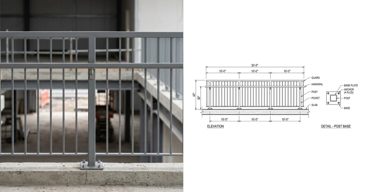
Railings are the trade where a drawing that is dimensionally perfect can still be illegal, and a drawing that is code perfect can still be unbuildable. The heights come from two different rule books that do not agree, the infill is checked with a sphere rather than a tape, and the run itself is set by a slab edge that was poured before anyone drew anything. Here is what a railing shop drawing has to carry, and why it cannot be finished from the architect's plan alone.
Our articles are still written by humans!
Get human written articles in your Google feed.
Why there are two heights
Start here, because it explains most of what a railing looks like. A guard and a handrail are different components with different purposes, and they are governed by different documents.
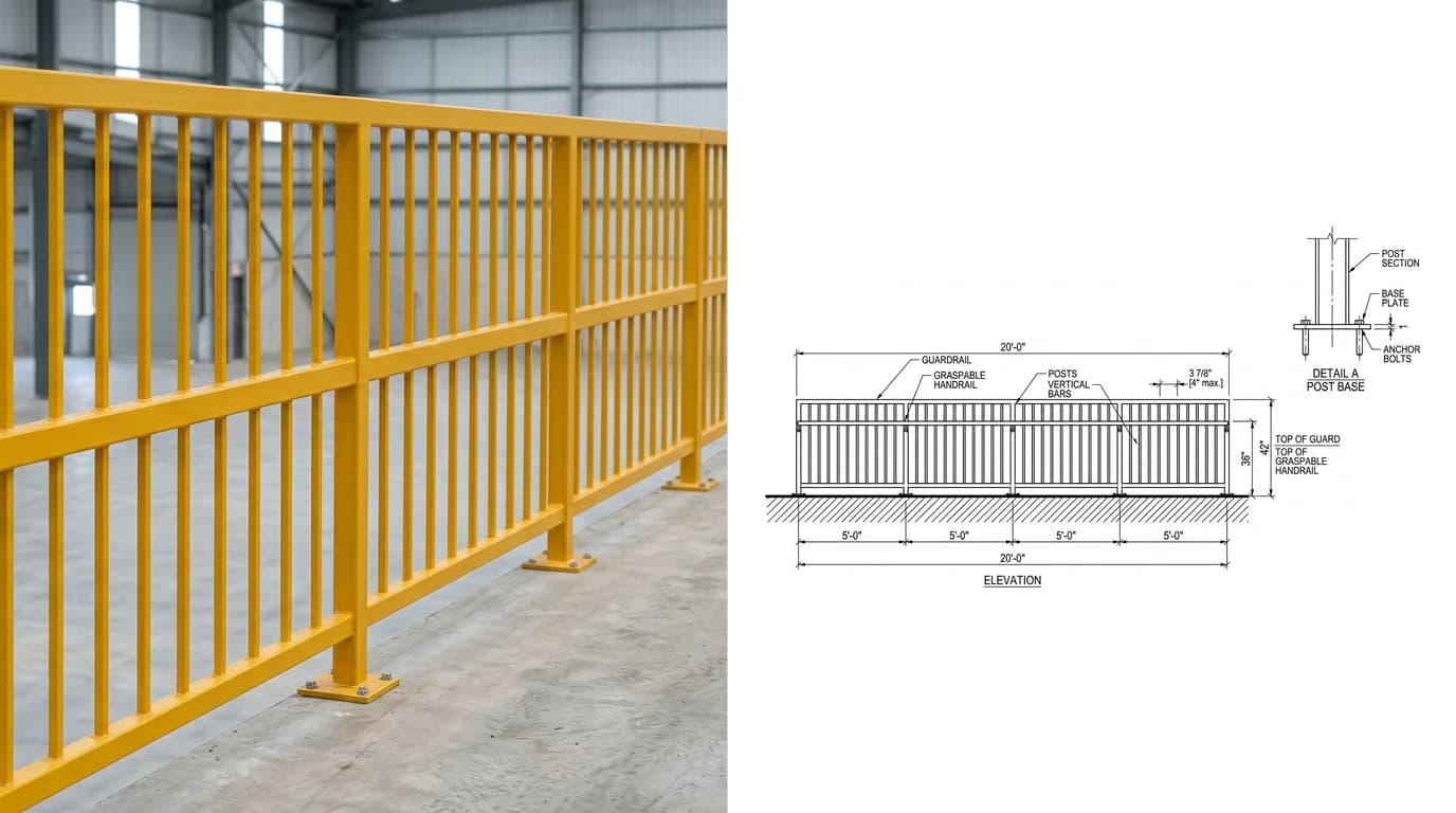
A guard is a barrier. Its job is to stop a person falling off an open edge, and in most commercial and multi-family situations it is required to be 42 inches high, measured from the walking surface. Nothing about that number has anything to do with hands.
A handrail is something to hold. Its job is to be gripped continuously while moving, and under Section 505.4 of the 2010 ADA Standards the top of the gripping surface has to be 34 inches minimum and 38 inches maximum above walking surfaces, stair nosings and ramp surfaces.
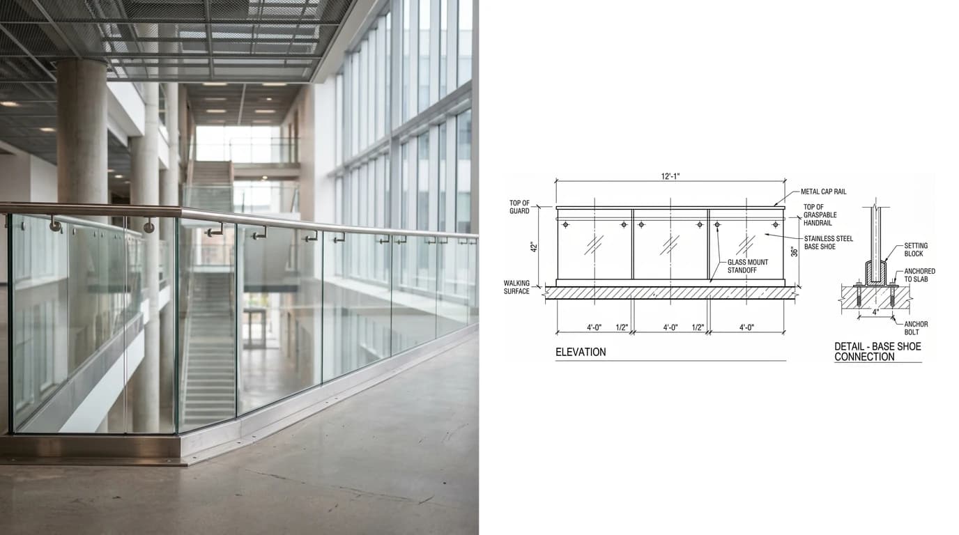
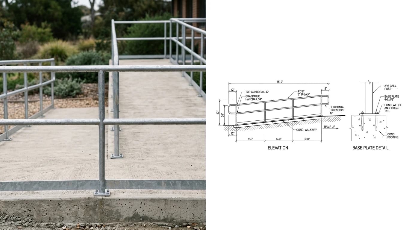
Put those side by side and the design follows immediately. A guard has to reach 42 inches. A handrail has to stop by 38. So a top rail that satisfies the guard is, by definition, too high to be the handrail. This is why so many commercial railings look the way they do: a top rail at guard height, and a second graspable rail mounted lower on the posts or on brackets.
What the guard has to resist
The structural requirement is short and frequently misquoted. Under IBC Section 1607.9.1, handrails and guards are designed to resist a linear load of 50 pounds per linear foot and a concentrated load of 200 pounds.
The part worth being careful about: the code lists both requirements, and it does not say they act at the same time. They are run as separate load cases, so the design is checked against each, not against the sum of the two. Adding them together is a common and expensive misreading that oversizes posts and base plates for no reason.
Two exceptions in the same section are worth knowing:
- For one- and two-family dwellings, only the single concentrated load applies.
- In Group I-3, F, H and S occupancies, for areas not accessible to the general public with an occupant load less than 50, the minimum linear load drops to 20 pounds per foot. That covers a lot of warehouse and industrial mezzanine work.
Infill is separate again. Under Section 1607.9.1.2, balusters, panel fillers and guard infill components, including all rails except the handrail and the top rail, are designed to resist a concentrated load of 50 pounds. That load is a check on the infill itself and is not added to the guard loads above.
Almost all of this lands on the drawing in one place: the post base detail. Post spacing, base plate size, anchor type, anchor quantity and edge distance from the slab edge are what actually carry the load, and a railing set with a beautiful elevation and a vague base detail has left out the engineering. Slab edge distance deserves particular attention, because an anchor too close to a free edge fails at a fraction of its rated capacity.
The sphere rules
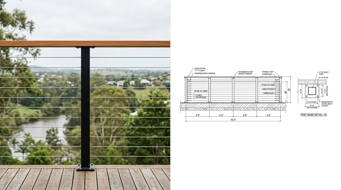
IBC Section 1015.4 sets the opening limitation, and the wording matters: required guards shall not have openings that allow passage of a sphere 4 inches in diameter, from the walking surface to the required guard height.
It is a sphere passage test, which means it is about the clear opening, not the picket centres. A picket layout dimensioned at 4 inches on centre with half inch pickets has a 3 and 1/2 inch clear gap and passes. The same drawing dimensioned only to centres forces the shop and the inspector to do the subtraction, and one of them will get it wrong. Dimension the clear gap.
IBC 1015.4 opening limitations and the exceptions that apply in specific places
The stair triangle catches people out constantly. At the open side of a stair the riser, the tread and the bottom rail form a triangle, and that specific opening gets a 6 inch sphere rather than a 4 inch one. It is a genuine relaxation and it exists because the geometry is unavoidable, but it applies to that triangle only, not to the rest of the guard.
What makes a handrail graspable
This is where decorative intent collides with the standards, and where a railing detailer earns their fee. The 2010 ADA Standards give two ways for a handrail to be graspable, and a profile has to satisfy one of them.
The two ADA options for a graspable handrail cross section
The circular case is easy, and it is why so much commercial handrail is 1 and 1/2 inch or 1 and 1/4 inch round tube: comfortably inside the range and cheap to bend.
The non-circular case is where designs fail. A wide flat cap rail can satisfy the 4 to 6 and 1/4 inch perimeter requirement and still fail the 2 and 1/4 inch maximum cross-section dimension. A 3 inch wide timber cap looks generous and reads as a handrail to a client, but it is over the cross-section limit. This is the single most common conflict between an architect's intent and a compliant submittal, and the honest answer is usually the two-rail solution again: keep the wide cap as the guard top rail and add a compliant graspable rail below it.
Two more clauses shape the bracket design. Section 505.5 requires 1 and 1/2 inches minimum clearance between the gripping surface and adjacent surfaces, so a rail cannot sit flat on a wall. Section 505.6 requires the gripping surface to be unobstructed along its top and sides, while the bottom may be obstructed for up to 20 percent of its length. That 20 percent is the allowance brackets live in, and it is why bracket spacing is a code question and not only a structural one.
Extensions and returns
Handrail extensions are the detail most often value-engineered out by someone who does not know they are required, and then reinstated at cost. The 2010 ADA Standards are specific.
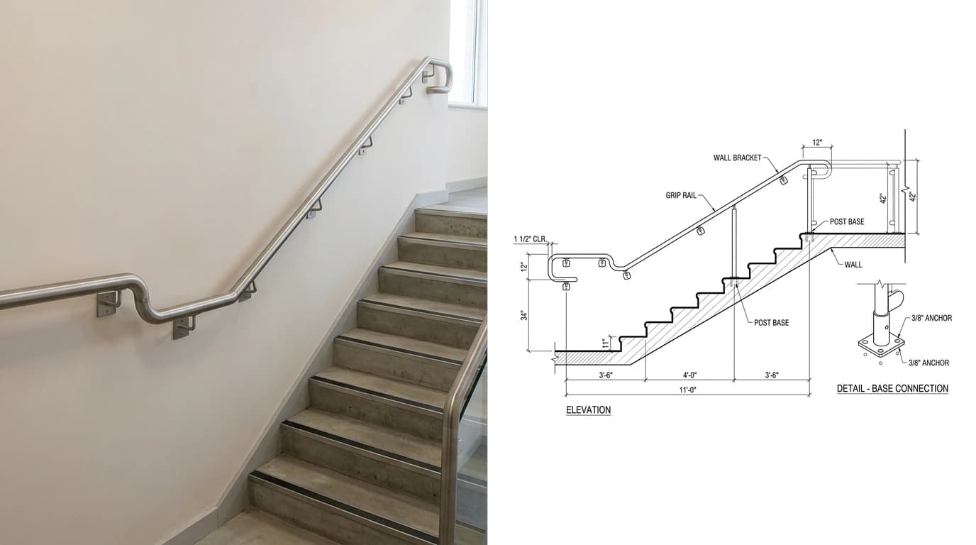
- Top of a stair flight, 505.10.2: the handrail extends 12 inches minimum horizontally above the landing, beginning directly above the first riser nosing.
- Bottom of a stair flight, 505.10.3: the handrail continues to slope for the depth of one tread beyond the last riser nosing. It is a sloped extension, not a horizontal one, which is a detail people get backwards.
- Ramps: handrails extend horizontally above the landing for 12 inches minimum beyond the top and bottom of ramp runs.
- Switchback and dogleg turns: inside handrails must be continuous around the turn, and no extension is required there.
Extensions have to return to a wall, guard or floor, and the handrail cannot rotate within its fittings. The length is measured to the start of the return radius, which is worth knowing because a detailer who measures to the end of the return will come up short. Horizontal portions also have to comply as protruding objects, which is why they cannot simply be extended into a circulation route. There is a limited allowance in alterations where a full extension would project into a circulation path and create a hazard.
The field measure is the drawing
Here is the sentence worth taking away from this article. A railing is fabricated to fit a structure that already exists, so the drawing is only as good as the measurements taken from that structure. Every other trade in this series argues something similar, but railings are the least forgiving because the tolerance is visible from six feet away.
A 30 foot run drawn from the architectural plan at even 5 foot post centres will not fit. The slab edge is not straight, the stair stringer landed where it landed, and the wall at the end is not plumb. What arrives on site is a run whose end bay is an inch and a half short, and the choices are all bad: cut a panel on site, leave an uneven bay, or take it back to the shop.
What a railing field measure has to record:
- The actual run length, measured, not scaled, at the height the railing will sit.
- The substrate you are anchoring into, and its thickness. Slab, topping, deck, stringer or wall all give different anchors.
- Edge distance available from the anchor to the free edge of the slab, which frequently governs the base plate size.
- Finished floor level at several points along the run, because heights are measured from the walking surface and floors fall.
- Stair geometry as built: actual riser height and tread depth, which set the rail slope and the extension lengths.
- Obstructions, columns, door swings and services that a post cannot land on.
- Whether the finish floor is down yet, since a base plate set before a topping pour ends up buried.
Then draw the post layout from the measured run, and set the end bays deliberately rather than letting the remainder fall wherever the arithmetic leaves it. The convention that works is equal end bays with the difference absorbed across the middle, because an eye reads the ends against the walls and never notices an inch spread across five interior bays.
From the drawing to the cut file
Once the layout is set, the geometry has to reach the machines. A metal shop doing railings typically runs a saw, a plasma or laser table for base plates and brackets, and a tube bender or roller for the rails themselves.
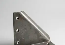
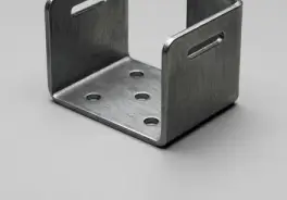
- Base plates and brackets go out as flat profiles with real hole positions. Closed paths, true scale, known units.
- Post lengths come off the drawing as a cut list, with the walking surface level accounted for at each post position rather than one length repeated.
- Rail lengths need the developed length around bends, not the sum of the straight segments, which is where hand takeoffs go wrong.
- Picket or cable positions as a drilled or punched pattern, matching the clear opening on the elevation.
- Handedness tracked, because a left hand and right hand bracket are two parts and one of them will otherwise arrive mirrored.
The mechanics are the same as any cutting workflow. DXF for plasma cutting covers kerf and lead-ins for plate work, why your DXF will not cut covers the failures that surface at the machine, and fixing a DXF that comes in at the wrong size covers the unit problem that turns a 6 inch base plate into a 6 millimetre one.
What gets a set sent back
- One height dimension instead of two. The reviewer cannot tell whether the assembly provides a compliant graspable handrail at all.
- Picket spacing dimensioned to centres rather than to the clear opening.
- Post spacing chain that does not total the run.
- A decorative cap rail called a handrail when its cross-section exceeds the 2 and 1/4 inch limit.
- No post base detail, or a base detail with no anchor type, quantity or edge distance.
- Extensions missing at the top or bottom of stairs and ramps, or the bottom extension drawn horizontal instead of sloped.
- No returns shown at the ends of handrails.
- Bracket clearance under 1 and 1/2 inches, or brackets obstructing the top or sides of the gripping surface.
- Survey status not stated, so nobody knows whether the dimensions are field measured or taken from the architect's plan.
- Mixed unit notation on one sheet, inches written three different ways. It reads as carelessness even when the geometry is right.
Where AI fits, honestly
There is a narrow place where AI saves a railing detailer real time, and a much larger place where it does not.
What it does well
Turning a site photograph into a scaled elevation you can detail over. Railing work is full of situations where that is exactly the input you have: matching an existing railing in a phased refurbishment, replacing a damaged section of a run nobody has drawings for, pricing from a client's photo before you send anyone to site, or documenting an existing installation during a survey. You photograph the run square on, anchor it to one dimension you actually measured, and get orthographic geometry at true scale that you export as DWG or DXF and detail in your own template. That is what TechDraw AI does. Getting dimensions from a photo explains the scale reference that makes it work, how to measure a part covers taking that reference properly, and if AutoCAD is where you detail, the AutoCAD handoff is a DWG you simply open.
What it does not do
Everything that makes it a railing drawing rather than a picture of a railing. A photograph cannot tell you the occupancy, and the occupancy sets the loads. It cannot tell you what is behind the slab edge, and that sets the anchors. It does not know that this assembly needs a graspable rail as well as a guard, or that the cap rail the client likes is over the cross-section limit. Most of all it cannot field measure: the run length, the floor levels along it and the as-built stair geometry are things somebody has to go and take.
Pre-fabrication checklist
- Two vertical dimensions shown: top of guard and top of gripping surface.
- Guard height correct for the occupancy and the adopted local code.
- Handrail height within 34 to 38 inches, consistent along the whole run.
- Infill dimensioned to the clear opening, not to picket centres.
- Stair triangle opening checked separately against the 6 inch sphere.
- Handrail profile checked against the circular or non-circular limits.
- Bracket clearance at least 1 and 1/2 inches, top and sides unobstructed.
- Extensions drawn at the top and bottom of every stair and ramp run.
- Returns shown at every handrail end.
- Post base detail with plate size, anchor type, quantity and edge distance.
- Post spacing chain totalling the overall run dimension.
- End bays set deliberately, not left as the remainder.
- Survey status stated: field measured or subject to field verification.
- Handed parts identified separately on the cut list.
- All dimensions in one unit notation throughout the set.
For the same submittal discipline in neighbouring trades, structural steel shop drawings covers the frame and the AISC 303 approval chain, sign shop drawings covers permit and fabrication sets, and shop drawings vs construction drawings places all of them against the contract documents.
Frequently asked questions
Why does a railing drawing show two different heights?
Because a guard and a handrail are two different things with two different jobs, and the code treats them separately. A guard stops people falling off an edge and in most commercial situations is required to be 42 inches high. A handrail is there to be gripped, and under the 2010 ADA Standards Section 505.4 the top of the gripping surface must be 34 inches minimum and 38 inches maximum above the walking surface, stair nosings and ramp surfaces. Those two ranges do not overlap, which is why a compliant assembly usually carries a top rail at guard height and a separate graspable handrail lower down.
What loads does a guardrail have to be designed for?
Under IBC Section 1607.9.1, handrails and guards are designed to resist a linear load of 50 pounds per linear foot and a concentrated load of 200 pounds. The code lists both as requirements and does not state that they act together, so they are run as separate design checks rather than added into one load. There are exceptions: for one- and two-family dwellings only the single concentrated load applies, and in Group I-3, F, H and S occupancies, in areas not accessible to the general public with an occupant load less than 50, the minimum linear load drops to 20 pounds per foot.
What is the 4 inch sphere rule?
IBC Section 1015.4 states that required guards shall not have openings that allow passage of a sphere 4 inches in diameter, from the walking surface to the required guard height. It is a clear opening test, not a centre to centre spacing, which is why a picket layout has to be dimensioned to the clear gap. There are exceptions worth knowing: from 36 inches to 42 inches the limit relaxes to a 4 and 3/8 inch sphere, assembly seating areas use an 8 inch sphere from 26 to 42 inches, and the triangular opening formed by the riser, tread and bottom rail at the open side of a stair uses a 6 inch sphere.
What are the ADA requirements for handrail cross section?
The 2010 ADA Standards give two options. Under Section 505.7.1 a circular handrail must have an outside diameter of 1 and 1/4 inches minimum and 2 inches maximum. Under Section 505.7.2 a non-circular handrail must have a perimeter dimension of 4 inches minimum and 6 and 1/4 inches maximum, and a cross-section dimension of 2 and 1/4 inches maximum. That last limit is the one that quietly rules out a lot of decorative profiles, because a handsome wide flat cap rail can pass the perimeter test and still fail the 2 and 1/4 inch cross-section limit.
How much clearance is needed behind a handrail?
Under Section 505.5 of the 2010 ADA Standards, clearance between handrail gripping surfaces and adjacent surfaces must be 1 and 1/2 inches minimum. Section 505.6 also requires that the gripping surface be unobstructed along its top and sides, while the bottom may be obstructed for up to 20 percent of its length. In practice this drives the bracket design and the bracket spacing, and it is why a handrail cannot simply be strapped flat against a wall.
What handrail extensions does ADA require at stairs and ramps?
At the top of a stair flight, Section 505.10.2 requires the handrail to extend 12 inches minimum horizontally above the landing, beginning directly above the first riser nosing. At the bottom, Section 505.10.3 requires it to continue to slope for the depth of one tread beyond the last riser nosing, then the extension returns to a wall, guard or floor. At ramps, handrails must extend horizontally above the landing for 12 inches minimum beyond the top and bottom of ramp runs. Inside handrails at switchback or dogleg turns must be continuous instead, and no extension is required there.
Why do railing shop drawings need a field measure?
Because a railing is fitted to a structure that has already been built, and the built structure is never exactly the drawing. Slab edges wander, stair stringers land where they land, wall faces are out of plumb, and a 30 foot run detailed from the architectural plan will have its end bay short or long by an inch or two. Field measuring before fabrication lets you set real post positions and real panel lengths, and it is why railing shops fabricate late in the programme rather than early.
Can I make railing shop drawings from a photo?
You can get a dimensioned starting point from a photo, and it is genuinely useful for matching an existing railing, replacing a damaged section, pricing from a client's picture, or documenting a run with no surviving drawing. Anchor the image to one real measurement you took and you get a scaled elevation you can detail over. What a photo cannot give you is the substrate you anchor into, the structural design, the code heights and clearances for that occupancy, or the field dimensions that make the run fit. Those come from the survey, the engineer and the code.
Sources
- 2010 ADA Standards for Accessible Design, Section 505 Handrails (ADA.gov)
- U.S. Access Board guide to the ADA Standards, Chapter 5: Stairways
- U.S. Access Board guide to the ADA Standards, Chapter 4: Ramps and Curb Ramps
- IBC Section 1607.9 Loads on handrails, guards, grab bars and seats (UpCodes)
- 2021 International Building Code, Section 1015.4 Opening limitations (ICC Digital Codes)