
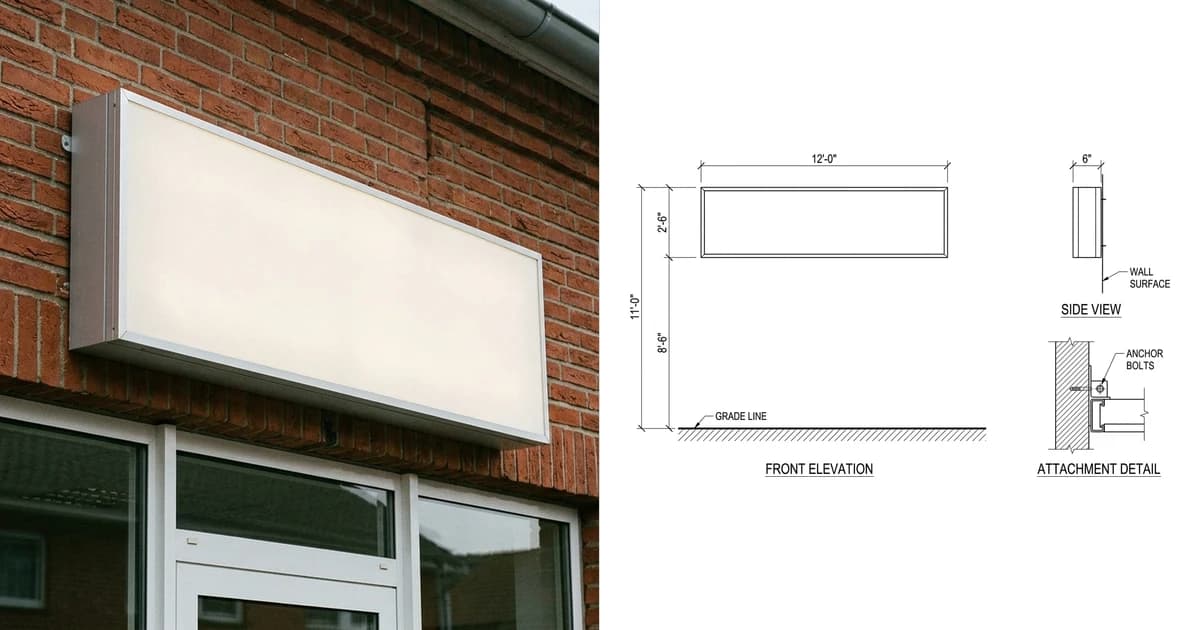
A sign drawing has an unusual problem. The same sheet has to satisfy a plan reviewer who cares about wind load and setbacks, and a shop that cares about return depth and weep holes, and neither of them wants to read the other one's information. Get that split wrong and you either fail the permit or fabricate something nobody can install. This is what each set has to carry, and which code sections a reviewer is actually reading when they look at yours.
Our articles are still written by humans!
Get human written articles in your Google feed.
You are drawing two sets, not one
Most trades produce a submittal for review and then fabricate from the same information. Signage is different, because two different authorities have to be satisfied and they want opposite levels of detail.
The same sign, two audiences, two sets drawn from one survey
The failure mode is drawing one set and hoping it covers both. A permit sheet crowded with weep hole positions and LED module counts irritates a reviewer looking for setbacks. A fabrication sheet that omits the return depth because the permit did not need it sends the shop looking for a phone number. Draw them separately, from one survey and one model, and keep the numbers in sync.
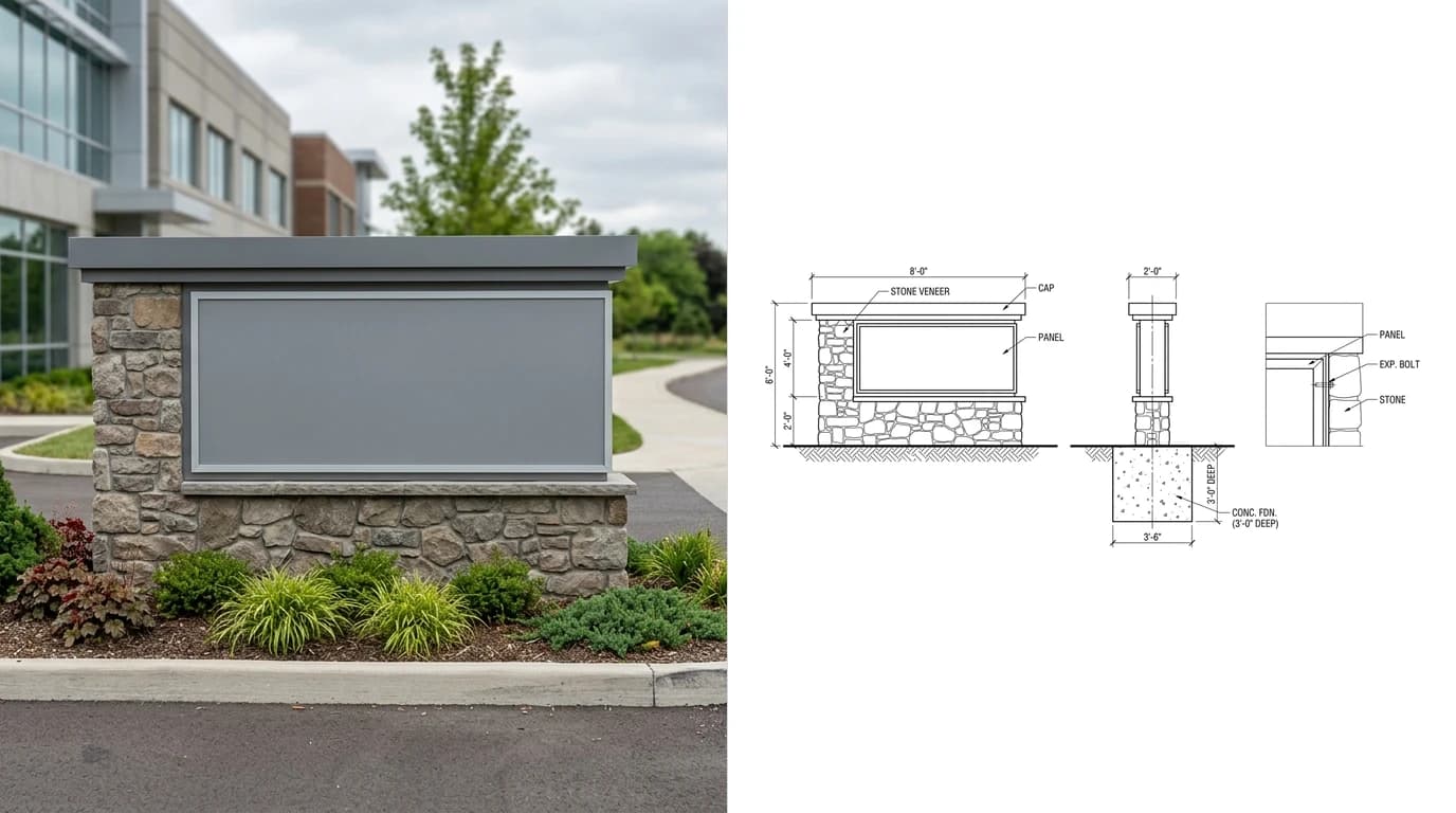
What the permit set has to show
The general requirement sits in IBC Appendix H, which is the model code chapter on signs. Two things are worth knowing about it before quoting it at anyone. First, Appendix H only applies where the jurisdiction has specifically adopted it, which many but not all have. Second, the local sign ordinance usually does the heavy lifting on what is allowed, while the building code covers whether it is safe. You need both.
On documents, Section H105.2 is direct: where a permit is required, construction documents shall be required showing the dimensions, material and required details of construction, including loads, stresses and anchors. That last clause is the one people skip. Loads, stresses and anchors are named in the code text itself, which is why a beautifully rendered elevation with no structural information behind it comes back with comments.
A permit set that clears review usually carries all of this:
- A site plan or building elevation locating the sign, with setbacks from property lines and distances to other signage.
- A dimensioned sign elevation with overall width and height, and the sign area calculated the way the local ordinance defines area, which is not always the rectangle you would expect.
- Height above grade to both the bottom and the top of the sign, measured from the finished grade or sidewalk the ordinance specifies.
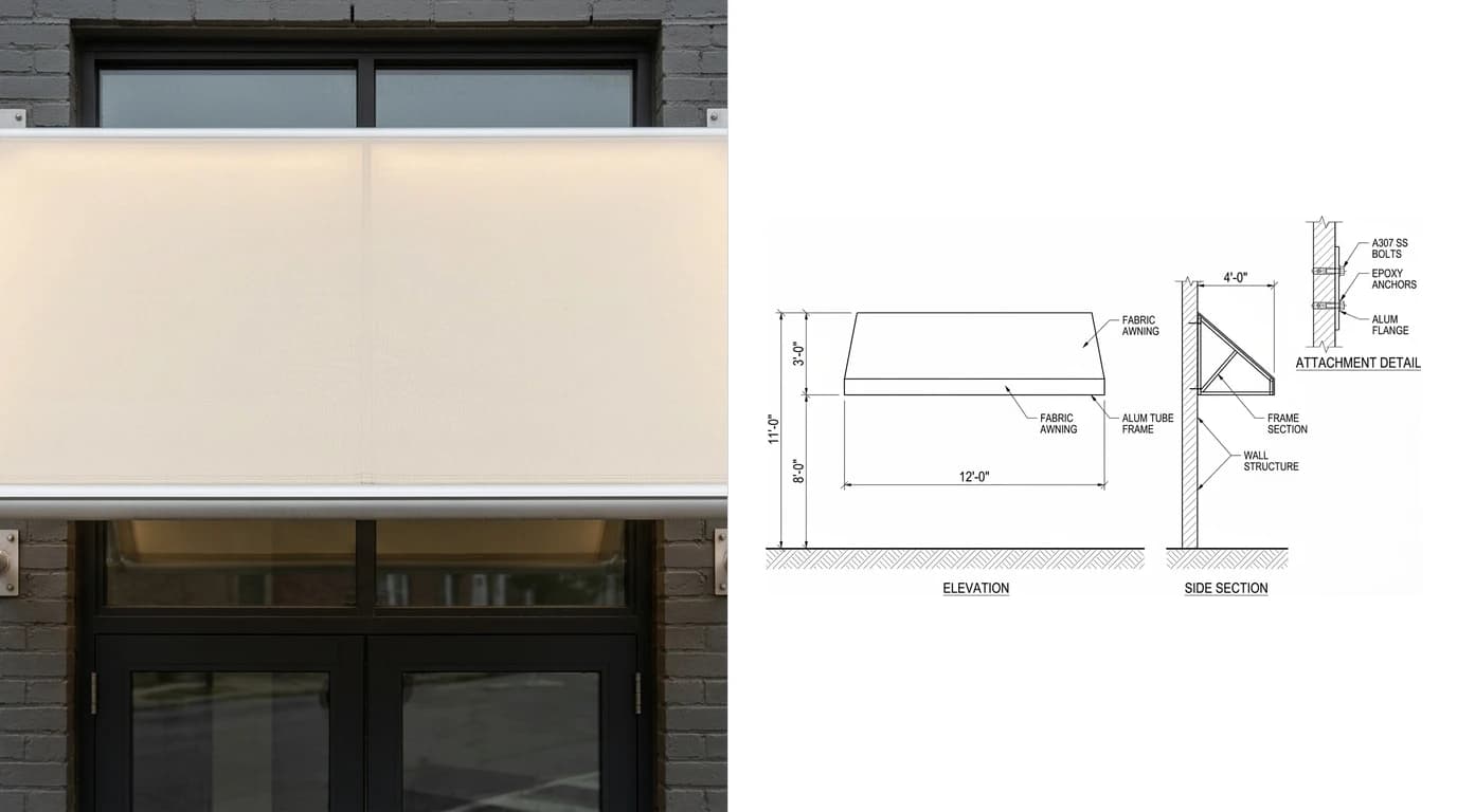
- A side view or section showing depth and projection from the wall face, which is what a projection limit is checked against.
- Materials and finishes named specifically, including the face material and the retainer.
- Structural support and an attachment detail, with the substrate identified.
- Electrical information for any illuminated sign, covering the listing, the supply and the disconnect.
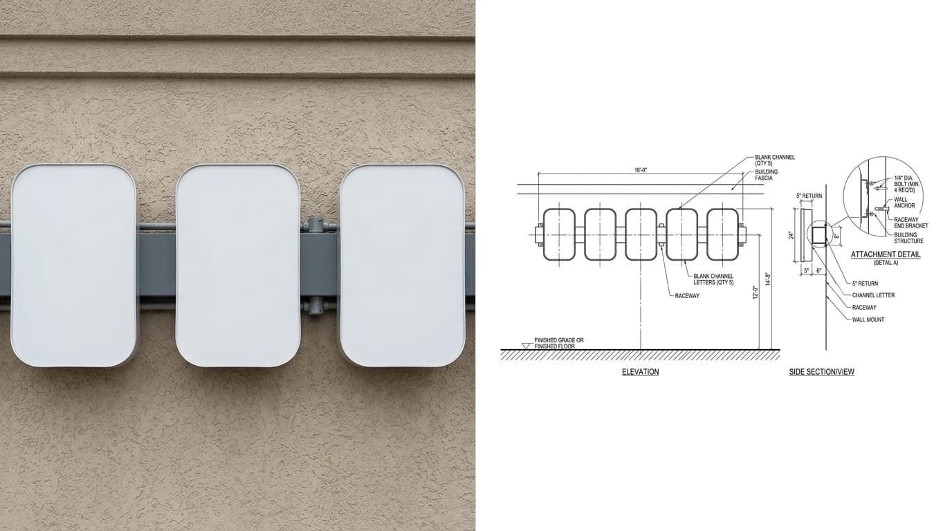
Wind, seismic and attachment
A sign is a structure that happens to have a graphic on it, and the code treats it that way. Section H105.1 requires signs to be designed and constructed to comply with the provisions of the code for use of materials, loads and stresses. Section H105.3 requires signs to be designed and constructed to withstand wind pressure. Section H105.4 requires signs to be designed to meet the seismic requirements of Chapter 16.
For a small wall-mounted cabinet this is usually satisfied by a standard detail and an anchor schedule. For a pylon on a single pole, a monument with a foundation, or anything large or tall, it means real engineering and often a stamped calculation. The drawing has to show the result: framing members and sizes, the pole or foundation, and the load path from the sign face into the ground or the building.
Attachment gets its own clause, and it is worth reading closely. Section H105.6 requires signs attached to masonry, concrete or steel to be safely and securely fastened by means of metal anchors, bolts or approved expansion screws of sufficient size and anchorage to safely support the loads applied. Note what the code assumes: masonry, concrete or steel. Modern storefronts are frequently none of those.
Why the attachment detail cannot be drawn before the survey identifies the substrate
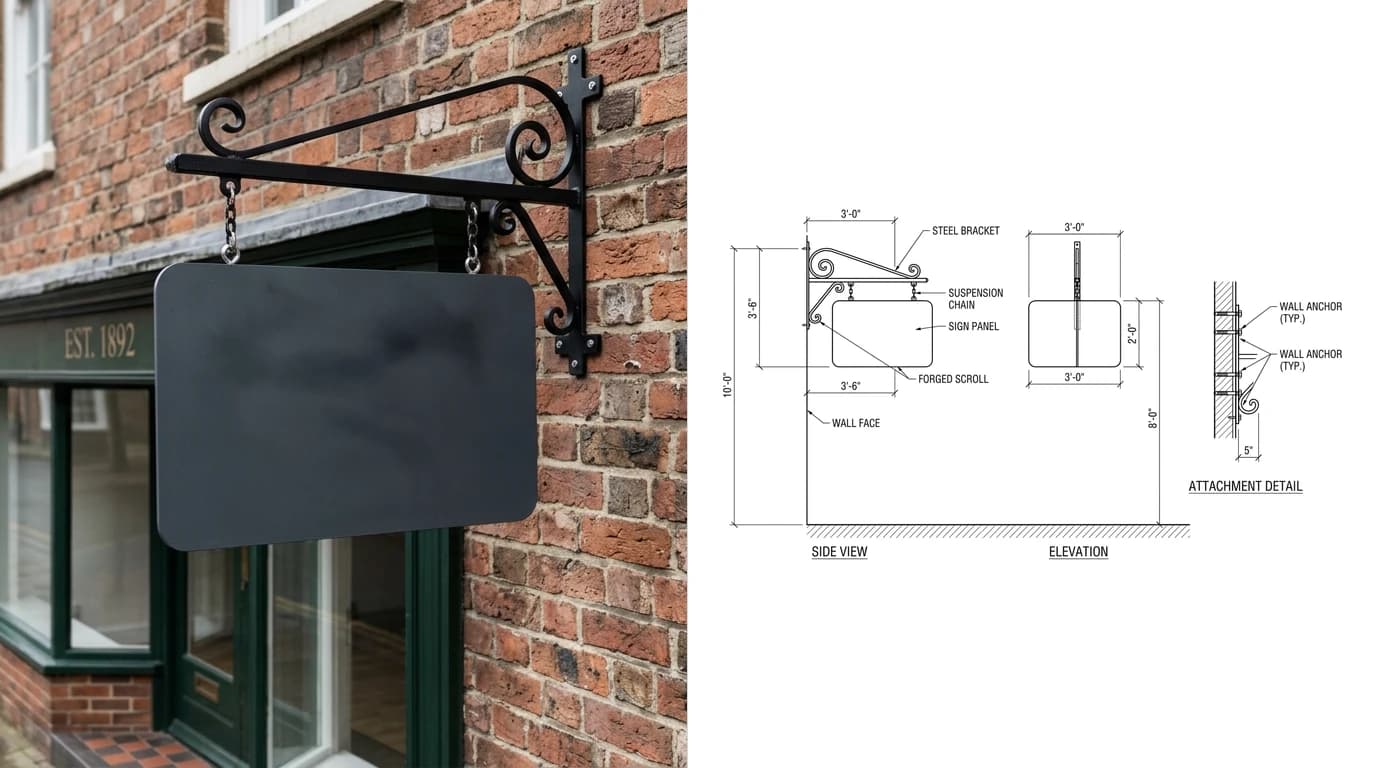
The electrical half nobody draws
Illuminated signs are electrical products, and two documents govern them. UL 48, the Standard for Safety for Electric Signs, governs the design and fabrication of the sign itself. NEC Article 600, in NFPA 70, governs the installation, conductors, equipment and field wiring. An inspector uses both.
The requirement that surprises people is listing. Electric signs, section signs and outline lighting are required to be listed and installed in accordance with the listing instructions. NEC Section 600.4 covers the required markings, including manufacturer identification and the electrical ratings, applied to the sign itself. A sign built in a shop that is not a listed manufacturer, or assembled from parts in a way the listing does not cover, is a real inspection problem rather than a paperwork one.
On the drawing, the electrical content that keeps submittals moving:
- The listing identified, with the mark that will appear on the finished sign.
- Voltage, current and circuit requirements, so the electrician sizes the supply correctly.
- The disconnect location, which the NEC treats as a real requirement rather than a convenience.
- The supply route and penetration, including how it crosses the building envelope and how that penetration is sealed.
- Power supply and module layout inside the cabinet or letters, on the fabrication set rather than the permit set.
The survey decides the drawing
Here is the sentence worth taking away from this article. Almost every expensive sign failure traces back to a survey assumption, not a drafting error. The drawing is only ever as good as what was measured and identified on site, and the things that hurt are the ones nobody photographed.
A survey that actually protects the job records:
- Fascia dimensions including the usable area between architectural features, not just the overall width.
- The substrate, established rather than assumed. If that means a small exploratory hole with the owner's permission, that is cheaper than a return visit with a crew.
- Existing signage on the property, because ordinances usually cap total area per tenant or per frontage.
- Grade conditions under the sign, since height is measured from grade and sites slope.
- Electrical availability, the panel location and a plausible route, not just that power exists somewhere.
- Access for installation: what equipment can reach the location, and whether a lane or sidewalk closure will be needed.
- Photographs from several distances, including one straight on and square to the fascia, which is the one you will actually draw from.
That last point matters more than it sounds. A photograph taken square to the wall, from far enough back that the perspective is mild, with one known dimension in frame, is a usable drawing input. One taken from ten feet away at an angle is a reference picture and nothing more.
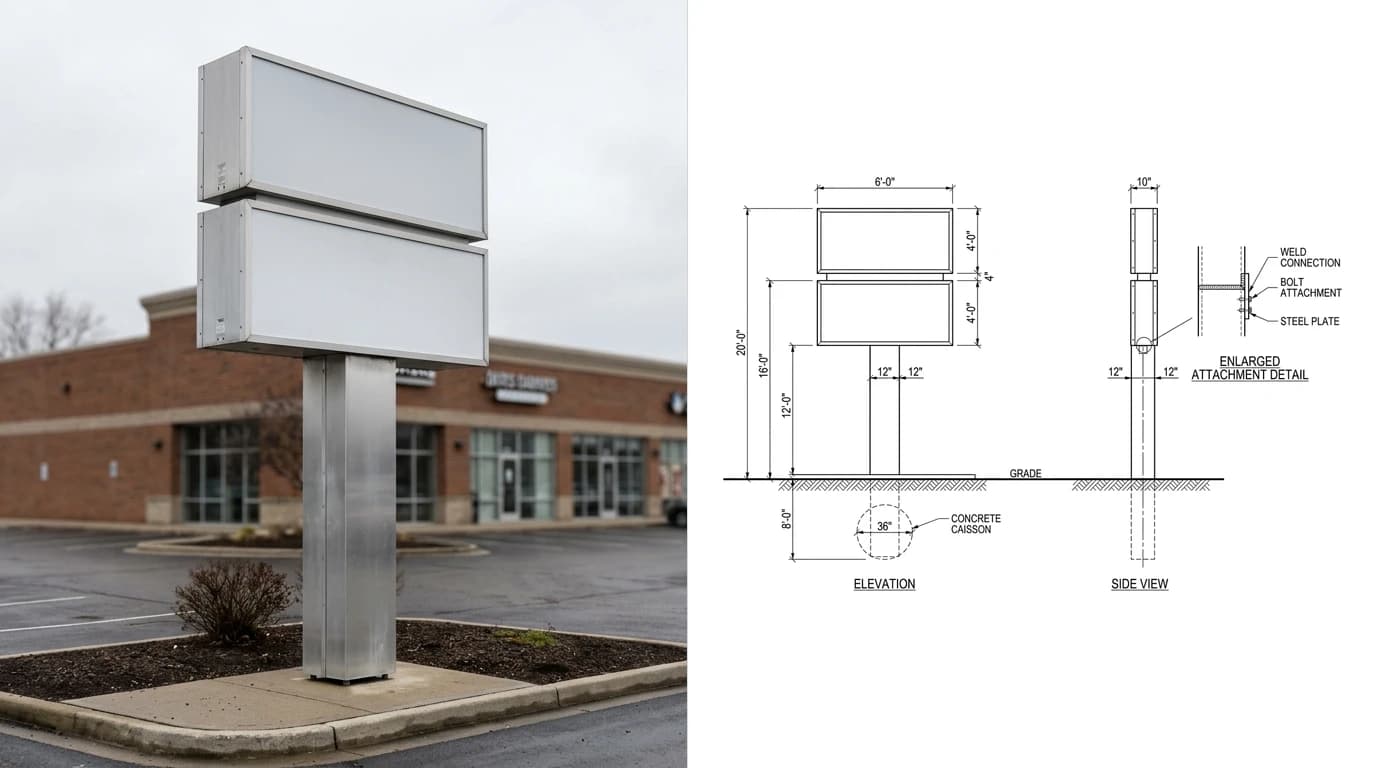
From the drawing to the router
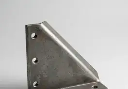
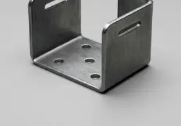
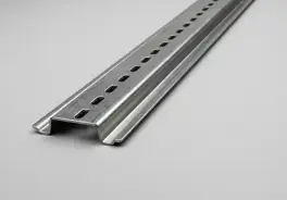
Once the permit is in hand, the same geometry has to reach the machines. A sign shop typically runs a CNC router for panels and letter faces, a channel letter bender for returns, and often a laser or plasma for brackets and steel frames. All of them want real vector geometry at true scale, which is a different discipline from drawing for a reviewer.
- Closed paths. A letter outline that looks closed but has a gap of a thousandth will not cut as a profile. This is the most common reason a file gets rejected at the machine.
- Real units. The file has to carry a known unit and a one to one scale. A traced outline that is roughly the right shape is not a cut file.
- Layers that mean something, separating cut, score, engrave and reference geometry, because the machine operator maps layers to tools.
- Letter geometry resolved: return depth, the back, the trim cap allowance and the weep holes, none of which appear on a permit elevation.
- Mounting hole patterns drawn as geometry, matching the pattern in the attachment detail, so what gets drilled matches what got approved.
The mechanics of getting clean vectors out are the same as any other cutting workflow. How to prepare a DXF for laser cutting covers closed paths and units, why your DXF will not cut covers the failures at the machine, and logo to vector for laser engraving covers the graphic side, which in signage is most of the work. For steel brackets and frames, DXF for plasma cutting covers kerf and lead-ins.
What gets a submittal rejected
- No height above grade. The single most common omission, and the first thing a reviewer looks for.
- Sign area calculated the wrong way for that ordinance, usually by measuring the cabinet when the ordinance measures the smallest rectangle enclosing the copy, or the other way round.
- No attachment detail, or a detail that names no substrate and no fastener size.
- No structural information on a sign large enough to need it, despite H105.2 naming loads, stresses and anchors.
- Electrical left blank on an illuminated sign, with no listing, no ratings and no disconnect.
- Existing signage not shown, so the reviewer cannot check the total area allowance.
- Drawings not to a stated scale, or a scale that does not survive being printed to a different sheet size.
- Projection over the public right of way not dimensioned, on a blade or projecting sign.
- Clearance above the sidewalk missing on anything pedestrians walk under.
- The rendering and the elevation disagree, which undermines confidence in the whole package.
Where AI fits, honestly
Signage is one of the better fits for photo-derived drawing, because the job genuinely starts from a photograph more often than in other trades. It is still worth being precise about the boundary.
What it does well
Turning a survey photograph into a scaled elevation you can detail over. You photograph the storefront square on, anchor the image to one dimension you actually measured, and get orthographic geometry at true scale that you export as DWG or DXF and open in your own template. That covers real sign work: drawing an existing sign you are replacing like for like, producing an elevation of a fascia you have to fit a new sign onto, documenting a multi-site rollout from photos, or pricing from a client's picture before anyone visits. That is what TechDraw AI does, and getting dimensions from a photo explains the scale reference that makes it work. If the input is a client's logo or artwork rather than a building, image to DXF converts the image itself into vector geometry, and cleaning up a jagged trace covers making the result cuttable.
What it does not do
Everything behind the surface. A photograph shows you a finish, not a substrate, and the substrate is what the attachment detail depends on. It carries no information about the electrical supply, the wind and seismic design, the anchor schedule, or the local ordinance limits on area, height and placement. It cannot tell you that the fascia is EIFS over studs, which is exactly the discovery that changes the job. And it cannot make the sign a listed product.
Pre-submittal checklist
- Local sign ordinance read for this jurisdiction, not assumed from the last job.
- Sign area calculated the way this ordinance defines area.
- Height above grade dimensioned to both bottom and top of the sign.
- Projection from the wall face dimensioned on anything projecting.
- Clearance above the sidewalk dimensioned where pedestrians pass under.
- Substrate identified from survey, not assumed from the finish.
- Attachment detail showing fastener type, size, quantity and spacing.
- Structural support shown, with calculations where the size warrants.
- Wind and seismic design addressed for the sign type.
- Listing, electrical ratings and disconnect shown for illuminated signs.
- Existing signage on the property shown for the area allowance.
- Every sheet at a stated scale that survives reprinting.
- Fabrication set separated, with return depths, weep holes and hardware.
- Cut files as closed paths at true scale in real units, layered by operation.
For the discipline in adjacent trades, the same submittal logic applied to structural steel is in structural steel shop drawings, to interior woodwork in millwork shop drawings, and the question of which of these documents is contractual at all is covered in shop drawings vs construction drawings.
Frequently asked questions
What are sign shop drawings?
Sign shop drawings are the technical documents a sign company produces for a specific sign on a specific building. In practice they serve two audiences at once. The permit set goes to the authority having jurisdiction and shows dimensions, placement, height above grade, materials, structural support and attachment. The fabrication set goes to the shop floor and adds the construction detail, the material schedule and the cut geometry the router and the channel letter bender need. The same project usually needs both, drawn from one survey.
What does a sign permit drawing have to include?
IBC Appendix H, Section H105.2 states that where a permit is required, construction documents shall be required showing the dimensions, material and required details of construction, including loads, stresses and anchors. In practice reviewers also expect the sign located on the building or site, its height above grade, the attachment method, and for illuminated signs the electrical information. Local sign ordinances then add their own limits on area, height and placement, and those vary by municipality, so the adopted local code always governs over any general description.
Does a sign need to be designed for wind load?
Yes. IBC Appendix H Section H105.3 requires signs to be designed and constructed to withstand wind pressure, and Section H105.4 requires signs to be designed to meet the seismic requirements of Chapter 16. Section H105.1 requires signs to comply with the code provisions for use of materials, loads and stresses generally. That is why a permit reviewer looks for support calculations, framing details and anchor specifications rather than only a pretty elevation, and why larger or pole-mounted signs usually need an engineer's involvement.
How is a sign attached and what does the drawing have to show?
IBC Appendix H Section H105.6 requires that signs attached to masonry, concrete or steel be safely and securely fastened by means of metal anchors, bolts or approved expansion screws of sufficient size and anchorage to safely support the loads applied. On the drawing that means an enlarged attachment detail showing the substrate, the fastener type and size, the quantity, and the spacing, not a general note saying the sign is securely mounted. The substrate matters: an anchor schedule that works into concrete is not the same schedule that works into hollow masonry or a metal stud fascia.
What is UL 48 and does my sign need it?
UL 48 is the Standard for Safety for Electric Signs, and it governs the design and fabrication of the sign itself, while NEC Article 600 governs the installation and field wiring. Together they are what an inspector uses to evaluate an electric sign. The NEC requires electric signs, section signs and outline lighting to be listed and installed according to their listing instructions, and NEC Section 600.4 sets out the required markings, including manufacturer identification and electrical ratings. Practically, this means an illuminated sign is a listed product and your drawing should identify the listing and the electrical characteristics rather than leaving them to the installer.
What is a sign survey and why does it matter?
A sign survey is the site visit where you record what is actually there: the fascia dimensions and construction, the substrate you will anchor into, the available electrical supply and its route, existing signage that may count against an area allowance, obstructions, and the sight lines. It matters because almost every expensive sign failure traces back to a survey assumption rather than a drawing error. A fascia that turns out to be EIFS over metal studs rather than solid masonry changes the attachment detail, the engineering and sometimes the whole mounting method.
Can I make sign shop drawings from a photo?
You can get a dimensioned starting point from a photo, and signage is one of the better fits for it because so much of the work starts from a photograph of an existing storefront or an existing sign. Anchor the image to one real measurement you took on site and you get a scaled elevation you can detail over. What a photo cannot give you is the substrate behind the finish, the electrical supply, the wind and seismic design, the anchor schedule, or the local ordinance limits. Those come from the survey, the engineer and the code, and they are what the permit reviewer is actually reading.
What file format does a sign router need?
Most CNC routers, laser cutters and channel letter benders in a sign shop take DXF, and many take vector formats such as EPS or AI for the graphic side. The important thing is that the geometry is real closed vector paths at true scale in a known unit, not an image traced loosely by eye. Letter returns, cutouts, weep holes and mounting hole patterns all have to be geometry the machine can follow, which is why the fabrication set is drawn separately from the permit set even when they show the same sign.
Sources
- 2021 International Building Code, Appendix H Signs (ICC Digital Codes)
- 2021 IBC Appendix H, Section H105 Design and Construction (ICC Digital Codes)
- Electric sign safety governed by UL 48 and NEC Article 600 (Eurofins Electrical & Electronics)
- NEC requirements for listed signs, NEC Section 600.1 (UL Code Authorities)
- National Electrical Code and signs (International Sign Association)