
The part is on the bench, the machine is down, and nobody can find a drawing. Getting a replacement made starts with measuring what you have, and measuring is where most reverse engineering quietly goes wrong. Not because people cannot read a caliper, but because they write down what the part is now instead of what it was designed to be.
Our articles are still written by humans!
Get human written articles in your Google feed.
The short answer
Sketch the part before you touch it with a tool. Measure the features that control function with a micrometer and the rest with a caliper. Round every reading to the nominal size it is obviously aiming at. Identify anything standard, threads, bearings, seals, by measurement plus a table rather than by drawing it. Take every dimension from one datum face. Then photograph the part and put the numbers on a drawing while it is still in front of you.
The kit that actually matters
You can reverse engineer most mechanical parts with a surprisingly small set of tools, and buying more precision than you can use is a common early mistake. What matters is knowing which tool is trustworthy for which measurement.
What to measure with what
Two habits matter more than the tools. Zero the instrument before every session and check it against a known gauge block or a new drill shank. And measure everything twice, ideally after putting the part down and picking it up again, because a caliper held slightly cocked reads consistently wrong in a way that looks perfectly convincing.
Read the number, then find the intent
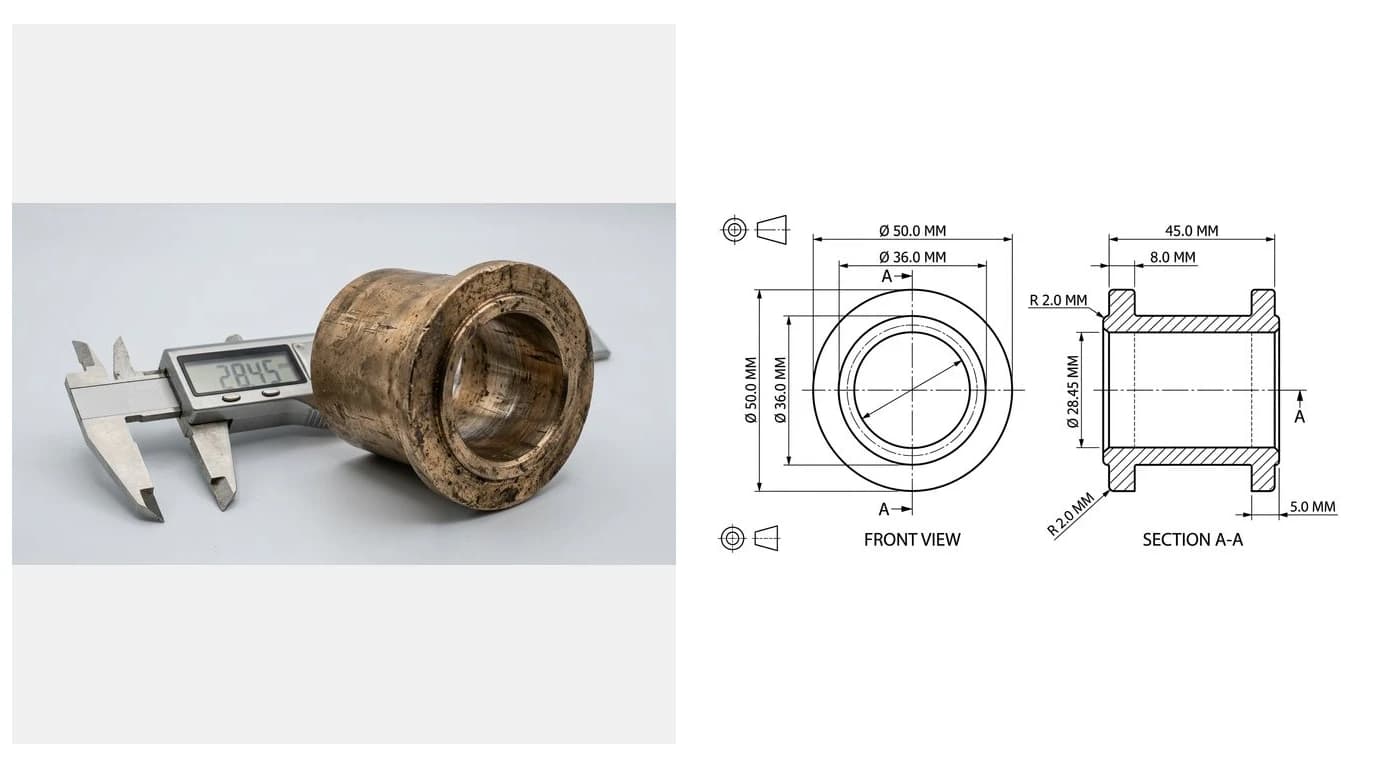
This is the single most important idea in this article. Your caliper reports the part as it exists: after machining tolerance, after wear, after a repair somebody made in 1994. Your drawing has to describe the part as it was designed. Those are different numbers, and copying the first into the second is how a replacement comes back worse than the one it replaced.
A reading of 24.94 mm on a shaft is not a 24.94 mm shaft. It is a 25 mm shaft, made to a fit, possibly with a few hundredths of wear. A hole reading 10.06 mm is a 10 mm hole. A wall reading 3.12 mm is 3 mm.
Where nominal sizes cluster
- Whole and half millimetres for most metric design work.
- Preferred metric bores and shafts at 5, 6, 8, 10, 12, 15, 16, 17, 20, 25, 30, 35, 40, which is also the bearing bore series and is not a coincidence.
- Inch fractions expressed in millimetres: 3.175, 6.35, 9.525, 12.7, 15.875, 19.05, 25.4. If your readings keep landing near these, you are holding an imperial part.
- Standard stock sizes for plate, bar and tube, since many parts start as bought material and one dimension is simply whatever the stock was.
Rounding to nominal does not mean guessing. It means separating two questions that get muddled: what size is this feature and how tightly does it need to be held. The first is the nominal. The second is a tolerance and a fit class you choose on purpose, in the way tolerances on a drawing describe, rather than something you inherit from a worn sample.
Measuring a part that is worn
You are usually reverse engineering a part precisely because it failed, which means the surfaces you most want to measure are the ones you can least trust. Wear is not evenly distributed, and that asymmetry is what saves you.
- Find the unworn region. Journals wear where the bearing ran, not under the shoulder. Bores wear in the loaded arc, not all the way round. Gear teeth wear on the working flank. Sealing faces wear in a band. Measure outside the worn zone and you get the original size directly.
- Measure in several planes. A bore measured in one direction tells you nothing about whether it has gone oval. Take it at zero and ninety degrees, and at both ends. The largest reading is usually the wear, the smallest is usually closer to nominal.
- Measure the mating part instead. If the shaft is ruined, the housing or the bearing that ran on it still knows what the shaft was. This is often faster and more reliable than any amount of careful work on the damaged item.
- Reassemble the broken pieces. For a cracked or snapped part, fit the fragments back together dry and measure across the assembly, then treat the crack as having zero width.
- Say so on the drawing. Note which dimensions were reconstructed rather than measured. The shop reads that note and knows where to ask.
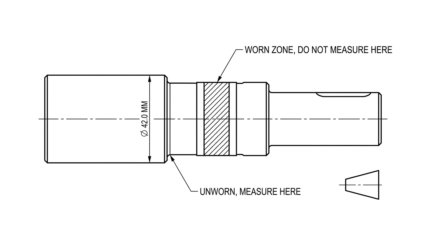
The wear trap is the reason a copied part often fails sooner than the original, and it is covered from the sourcing side in our guide to obsolete machine parts, which deals with what to do when the manufacturer will not supply one.
Threads: the one you cannot eyeball
Threads are where confident people get it wrong, because the common sizes are close enough together that a wrong answer still looks plausible until the part arrives.
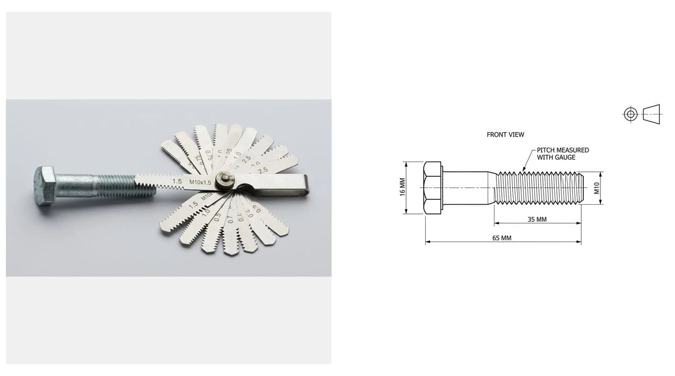
- Major diameter with a caliper, across the crests. A nominal M10 bolt measures around 9.8 mm, not 10.0, because the thread is cut slightly under.
- Pitch with a gauge, never by eye. Try leaves until one seats along the thread with no light under it. Metric leaves are marked in millimetres of pitch, imperial leaves in threads per inch.
- Check the family. 9.8 mm major with 1.5 mm pitch is M10 coarse. The same major with 1.25 mm is M10 fine, and the two do not interchange.
- Watch for pipe threads. A fitting called half inch BSP or NPT does not measure half an inch anywhere. It is named for a nominal bore, and NPT is tapered, so a caliper across the crests will not match the name at all. Measure it, then look up the designation.
Common metric threads and what a caliper actually reads
Bearings, seals and o-rings
Standard components are not drawn, they are identified. Getting this right removes whole features from your drawing and replaces them with a part number, which is both faster and far more likely to be correct.
Bearings
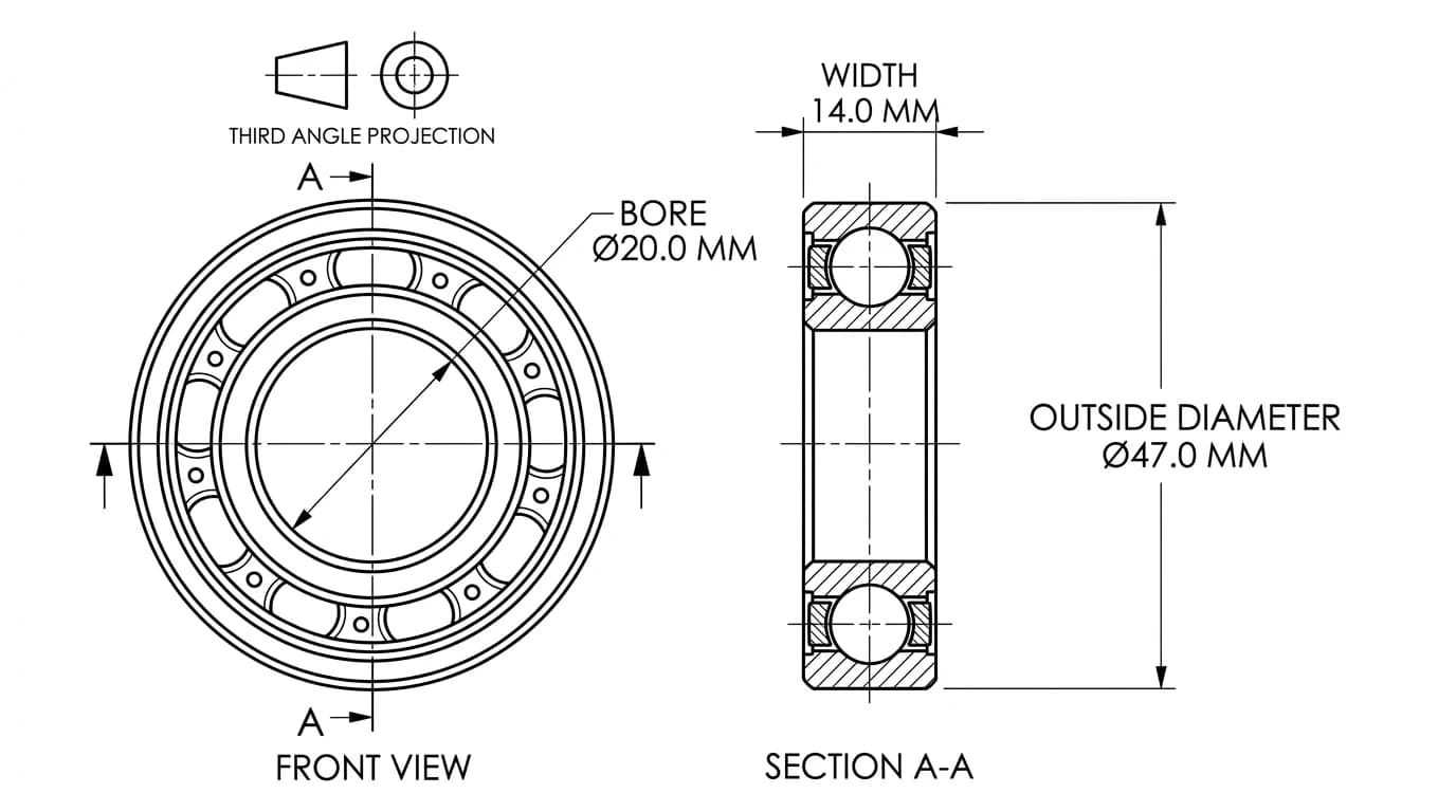
Boundary dimensions are standardised, so three measurements identify a bearing: bore, outside diameter and width. A bearing measuring 25 by 52 by 15 mm is a 6205. If any markings survive, read them first and use the measurements to confirm. What you then put on your drawing is the housing bore and the shaft diameter with their fit classes, not a drawing of the bearing itself.
Seals and o-rings
A radial shaft seal is identified by shaft diameter, housing bore and width, usually printed on the seal itself. O-rings are identified by inside diameter and cross-section, and the trap is that an o-ring that has been in service is stretched and set. Measure a relaxed one on a flat surface, or better, measure the groove it sits in and size the ring from that. Both metric and inch series exist and they interleave awkwardly, so quote the designation rather than the raw numbers.
Bores, holes and hole patterns
Internal features are where casual measuring falls apart, because the tool that is easiest to reach for is the one least suited to the job.
- Caliper jaws are not a bore gauge. The inside jaws have a radius at the tip and no way to find the true diameter, so they read small and inconsistently. Fine for a clearance hole, useless for a bearing seat.
- Use a telescoping gauge, lock it, and transfer to a micrometer. Rock it through the diameter to find the largest reading, which is the actual diameter.
- Measure hole positions, not gaps. Take centre to centre by measuring edge to opposite edge and subtracting one hole diameter, or measure both edges from the same datum face.
- Bolt circles are polar. For a circular pattern, count the holes, measure across two opposite ones if the count is even, and state a pitch circle diameter with an angular spacing rather than a list of coordinates.
- Check for counterbores and countersinks. They are easy to miss on a photograph and they change which fastener fits.
Measure from a datum, not from the last cut
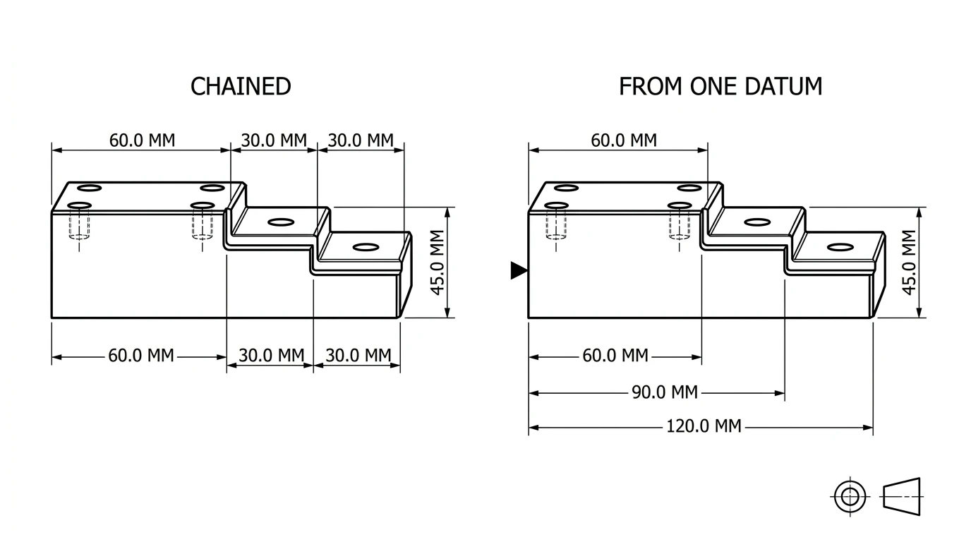
If you measure step to step along a part, every reading carries the error of the one before it. Five features later, the accumulated error can be larger than any tolerance you would have put on the drawing. This is the same failure as chained dimensioning, and it has the same fix.
Pick one face as the origin, ideally a face the part is actually located from in service, and take every longitudinal dimension from that face. Do the same for the two other axes. Each measurement now carries only its own error, and the drawing you produce tells the shop where to locate from, which is information the original drawing would have carried.
The features people forget
A drawing that is dimensionally perfect can still produce an unusable part, because the things that got left off are the things nobody thinks to measure.
- Chamfers and break edges. Usually 45 degrees by 0.5 or 1 mm. Leave them off and a shop either guesses or leaves sharp edges that will not assemble.
- Fillet radii. Internal corners carry stress. A radius gauge takes ten seconds and prevents a part that cracks where the original did not.
- Material. A magnet separates ferrous from non-ferrous, weight and colour separate aluminium from steel from brass from bronze, and a spark test narrows steels. If it matters structurally, get it analysed rather than assumed.
- Hardness and heat treatment. A shaft that was case hardened and is reproduced soft will fail quickly, and nothing about its dimensions tells you that happened.
- Surface finish and coatings. Anodising, plating and black oxide all add thickness as well as protection, so a plated part measures larger than the machined size underneath it.
- Direction and handedness. Left hand threads, one way bearings and asymmetric parts that look symmetric. Mark orientation on your sketch before the part goes back in the box.
Sketch first, measure second
The order matters more than it sounds. Draw the part freehand first, roughly to proportion, with every feature on it and no numbers. Then walk round the sketch adding measurements to the features you already drew.
Doing it this way catches the omissions while the part is still in your hand. If you measure first and sketch afterwards, you find out what you forgot at the point where the part has gone back into the machine, and every missing number costs a trip. Photograph the part from several angles at the same time, including the faces you think are boring, because those are the ones you will want later.
Getting it onto a drawing
Measurements in a notebook are not a deliverable. A shop quotes from a drawing, and the gap between the two is where most of the time in this job actually goes, since transcribing a known part into CAD is mechanical work rather than engineering.
- Take the measurements first, with the tools above, rounded to nominal, on your sketch.
- Photograph the part square on against a plain background, one shot per view you want, plus close-ups of anything fiddly.
- Generate the drawing and anchor the scale with one of your measurements, using TechDraw AI for machine parts. A photo has no absolute size on its own, which is why the anchor is not optional and why getting dimensions from a photo always starts with a known reference.
- Check the generated dimensions against your notebook, not against the photo. The part is the source of truth.
- Add what a photo cannot see: material, heat treatment, finish, tolerances on the fits, thread designations, the bearing part number.
- Export and send as PDF for reading and DXF or DWG for machining.
The wider workflow, including when a 3D scan is worth it and when it is not, is covered in how to reverse engineer a part without the original drawing, and what the finished sheet has to carry before a shop will quote it is in what makes a drawing manufacturing ready.
The measuring checklist
- Sketch drawn before any tool touched the part, every feature on it.
- Metric or imperial decided from three or more readings, not one.
- Every reading rounded to a nominal, with the odd ones out justified rather than copied.
- Worn surfaces avoided, or the original size recovered from an unworn region or the mating part.
- Fits measured with a micrometer and a bore gauge, not a caliper.
- Threads gauged, never estimated.
- Standard parts identified by designation rather than drawn.
- All dimensions taken from one datum face per axis.
- Chamfers, radii, material and finish recorded, not left for the shop to invent.
- Reconstructed dimensions flagged as reconstructed.
Work through that and the drawing you produce describes the part that was designed rather than the one that failed. Measure carefully, photograph the part while it is still on the bench, and let TechDraw AI do the drafting so your attention stays on the handful of numbers that decide whether the new part fits.
Frequently asked questions
What tools do I need to measure a part for reverse engineering?
A 150 mm digital caliper does most of the work. Add a 0 to 25 mm micrometer for anything that has to fit, a thread pitch gauge in both metric and imperial, a radius gauge set, and a small steel rule. Telescoping or small hole gauges used with the micrometer handle bores properly, because caliper jaws measure an internal diameter badly. That kit covers the large majority of mechanical parts.
How accurate is a digital caliper?
A decent digital caliper resolves to 0.01 mm and is accurate to roughly plus or minus 0.02 to 0.03 mm on an external measurement, which is fine for most reverse engineering. It is considerably worse on internal diameters and depths because of the jaw geometry and the leverage involved. For anything that has to be a fit, use a micrometer for outside diameters and a bore gauge or telescoping gauge for inside ones.
How do I know if a part is metric or imperial?
Measure several features and look at where the numbers land. If they cluster on whole and half millimetres, it is metric. If they cluster on multiples of 25.4 divided by simple fractions, it is imperial: 6.35 mm is a quarter inch, 12.7 mm is half an inch, 19.05 mm is three quarters. One imperial-looking value can be coincidence. Three in a row is an answer, and it changes every thread, bearing and fastener you then specify.
How do I measure a thread?
Take the major diameter across the thread crests with a caliper, then find the pitch with a thread pitch gauge by trying leaves until one seats with no light showing. Metric gauges read the pitch in millimetres, imperial gauges read threads per inch. A bolt measuring 9.8 mm major with a 1.5 mm pitch is M10 by 1.5. Never estimate a pitch by eye or by counting crests against a rule, because the common sizes sit close enough together to fool you.
How do I identify a bearing from the old one?
Measure three things: the bore, the outside diameter and the width. Those three numbers identify a standard bearing almost uniquely, because the boundary dimensions are standardised under ISO 15. A bearing that measures 25 by 52 by 15 mm is a 6205. If the old bearing still has legible markings, read them first and use your measurements to confirm rather than to guess.
Can I reverse engineer a part from a photo instead of measuring it?
Partly. A photo gives you geometry, proportion and feature layout, but it carries no absolute scale, so it cannot tell you how big anything is until you anchor it with at least one real measurement you took with a tool. The efficient workflow is to measure the handful of dimensions that matter, photograph the part, and let the drawing be generated with your measurements applied rather than transcribing every feature by hand.
Should I round a measurement to a nominal size?
Almost always, and this is the skill that separates a usable drawing from a bad one. A shaft that measures 24.94 mm was designed as 25 mm and has been machined to a tolerance or worn slightly. Copying 24.94 onto a drawing bakes somebody else's wear into your new part. Round to the intended size, then decide the tolerance and fit separately, and only keep an odd number when you have a reason to believe it was deliberate.
Sources
- ISO 286-1:2010 Geometrical product specifications (GPS), ISO code system for tolerances on linear sizes, Part 1: Basis of tolerances, deviations and fits
- ISO 15:2017 Rolling bearings, Radial bearings, Boundary dimensions, general plan
- ISO 3601-1:2012 Fluid power systems, O-rings, Part 1: Inside diameters, cross-sections, tolerances and designation codes
- Single View Metrology in the Wild (ECCV 2020): absolute scale cannot be recovered from one image without a known reference