
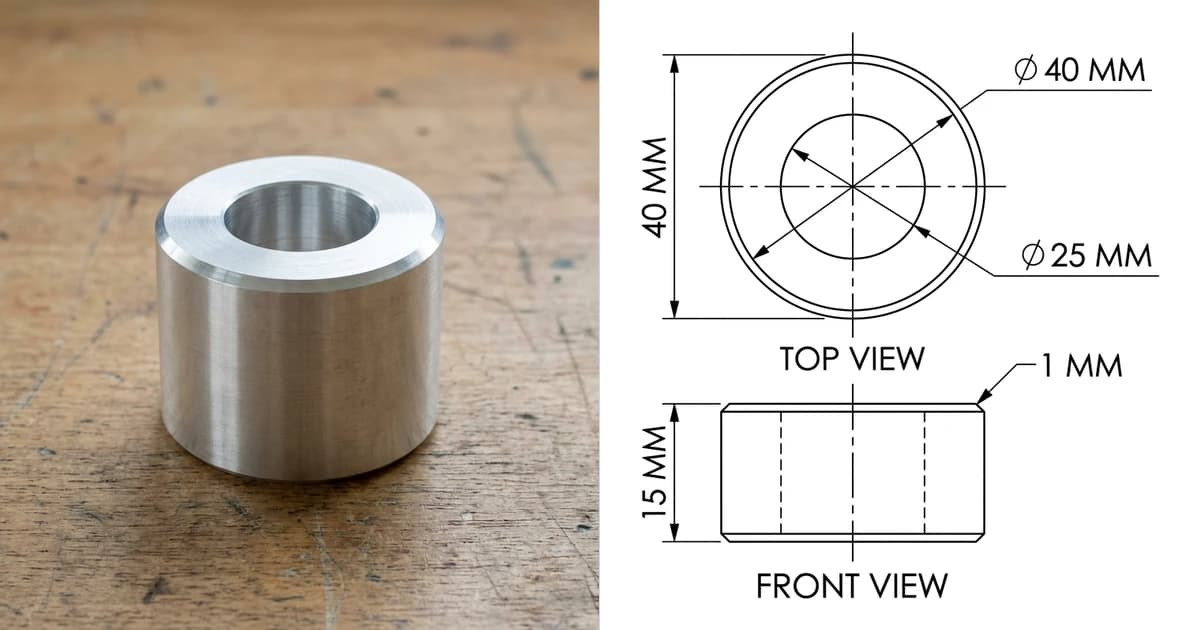
Every few minutes someone uploads an STL to a converter, downloads a STEP, opens it in CAD and finds a lumpy shell of a hundred thousand tiny flat faces that no command will touch. The converter did not fail. The conversion you wanted is not the one that exists, and understanding why takes two minutes and saves you an afternoon.
Our articles are still written by humans!
Get human written articles in your Google feed.
The short answer
You can always get a STEP file out of an STL. What you cannot get out of a converter is an editable solid, because the information you want back was destroyed when the STEP was meshed in the first place. Meshing is lossy in the same way that printing a photograph and scanning it again is lossy: the pixels are all there, the negative is gone.
So the practical question is never “which converter”. It is what do you need the model for, because that decides whether you need a rebuild, a reverse engineering pass, or nothing at all.
Why the conversion is hard
A CAD model stores a bore as a cylindrical surface with an axis and a radius. Export it as STL and that cylinder is replaced by, say, sixty narrow rectangles arranged in a ring, each a flat triangle pair. The file now says “these sixty flats exist”, and it no longer says “this is a cylinder of radius 10”.
Going back means guessing the intent. Were those sixty flats a cylinder, or a sixty-sided prism someone modelled deliberately? Is that slightly wavy region a plane with scan noise, or a real curve? Is the 0.4 mm step at the edge a chamfer or a meshing artefact? Software can make good guesses on regular machined shapes and poor ones everywhere else, and no guess is certain. That uncertainty is the whole story.
What the online converters actually do
Almost every free STL to STEP converter, and the free path in most CAD packages, runs the same operation:
- Read the triangles.
- Turn each triangle into a planar face bounded by three edges.
- Sew the faces into a shell, and if the shell closes, call it a solid.
- Write that out as a STEP file.
The result is a legitimate STEP that any CAD program will open. It is also a model where a round hole is not round, where Fillet and Shell have nothing sensible to work on, where clicking a face selects one triangle, and where the file is often ten to fifty times bigger than the STL it came from. If your only need is to hand a supplier something their system will accept, fine. If you intended to edit it, this is the point where people conclude the software is broken.
There is a middle step most converters skip
Between “one face per triangle” and “remodel it from scratch” sits something worth having, and it is the reason we eventually built our own converter rather than only writing this page. A flat surface arrived as hundreds of triangles only because STL has no other way to say “plane”. Those triangles can be grown back into single faces, the straight runs along their edges collapsed into one edge, and the edges shared between neighbouring faces so the shell closes into a genuine solid.
How much that wins is worth stating exactly rather than enthusiastically, because it depends entirely on how much of your part is flat. Take a 120 × 80 × 8 mm plate with four 10 mm holes, tessellated the way a CAD export tessellates it:
The same plate through both approaches
The flat surfaces collapse completely, and they come back as six faces whether the mesh was cut finely or coarsely. The holes do not move at all: at 96 segments each, those 384 strips genuinely are 384 distinct planes, and calling them a cylinder would be inventing a radius the file no longer contains. Take the holes away and a prismatic part goes from 768 triangles to 6 faces. Hand the same converter a 3D scan and it will do almost nothing, because a scan has no true planes in it.
That is a model you can select faces on, sketch on, cut and extrude, and it opens in under a second. What it still is not is parametric: there is no feature tree, no dimension to retype, and any curve is still the ring of flat strips the mesh already had, because a cylinder’s radius was destroyed at meshing time and no amount of processing invents it back. Our STL to STEP converter does this in the browser and tells you the two numbers that matter — triangles in, faces out — so you can judge the result before you open it. Going the other way, STEP to STL is the easy direction and loses nothing you will miss.
What you get from each approach
The three routes that work
1. Remodel it, using the mesh as a reference
The unglamorous answer, and usually the right one. Import the STL into CAD, measure it on screen, and rebuild the part with normal sketches and features. If the mesh came from CAD rather than a scan, the measurements are exact, so you are copying numbers rather than estimating them. For a bracket or a housing this is an hour of work and it leaves you with a proper feature tree, which the converted version never has.
2. Reverse engineer it, with tools that fit surfaces
Software that recognises regions of the mesh and fits real geometry to them: Fusion's prismatic conversion, SolidWorks ScanTo3D, Geomagic Design X, QuickSurface, Rhino with RhinoResurf. On a machined part with flat faces, cylinders and simple fillets, these are genuinely good. On an organic shape or a noisy 3D scan you are back to modelling by hand over the mesh. The full workflow is in how to reverse engineer a part.
3. Do not convert at all
Ask what breaks if the file stays a mesh. Printing, scaling, hollowing, repairing and rendering all work better on the mesh than on any solid you could convert it into.
Doing it in Fusion, FreeCAD and the rest
Autodesk Fusion
Insert the mesh, then Mesh tab, Modify, Convert Mesh. Three methods: faceted, organic and prismatic. Prismatic is the one worth having, because it recognises planar and cylindrical regions and produces a genuinely usable solid on mechanical parts, and Autodesk restricts it to commercial licences rather than the free personal one. It also fails on meshes it cannot make sense of, at which point Autodesk's own advice is to fall back to faceted. Then File, Export, STEP.
FreeCAD, free and open source
Switch to the Part workbench, select the imported mesh, then Part, Convert to shape. Run Refine shape afterwards, which merges coplanar faces and cuts the face count substantially on flat-sided parts. Then File, Export, STEP. This is the faceted route, so temper expectations, but on a simple prismatic part with large flats the refine step can leave something you can actually work with.
The browser converters
They run the same faceted operation with a nicer button. They are fine for small files and a quick result, and worth avoiding for anything confidential, since the model leaves your machine. Watch the file size after conversion: it is the fastest way to tell what you were given.
When you do not need a STEP at all
- You are printing it. The slicer wants a mesh. Keep the STL, or better, a 3MF.
- You are scaling or repairing it. Mesh tools, not CAD.
- You need one small change. Cutting a hole or trimming a boss is often easier as a direct mesh edit in Blender or Meshmixer than as a conversion.
- You need it cut flat. If the part is sheet material, what you actually want is a 2D profile in DXF, not a 3D solid, and you can check the result in the browser with the DXF viewer.
When the part is in your hand, not in a file
A surprising share of STL to STEP searches start with a physical object: someone printed a part, or scanned one, and now a supplier wants something a machine shop can quote. If that is you, the mesh is a detour. What the shop needs is the shape plus the numbers, and the numbers are the half no mesh contains.
Two honest routes. Measure the part properly and model it, which is the gold standard, or photograph it and let TechDraw AI produce the dimensioned 2D drawing, which exports as DWG, DXF, SVG or PDF and gives the shop something to quote from today. The same route is covered end to end in photo to CAD, and for a drawing that only exists on paper, in scan to CAD. Whichever you pick, send the mesh along with it: between the shape and the dimensions, a shop has everything it needs.
Photograph the part and get a dimensioned 2D drawing your shop can quote from, no mesh conversion involved.
Turn a photo into a drawingTwo smaller jobs come up constantly on the way there and neither of them needs a solid. If the mesh itself is the problem, and a slicer refusing it or a converter choking on it usually means it is, STL repair will tell you what is actually wrong with it before it changes anything: how many holes, how many faces are wound backwards, whether a shell is inside out. And if what you really need is not a solid at all but a flat profile to cut, take a section rather than a conversion — STL to DXF and STL to SVG slice the model with a plane you position yourself and give you the outline at true size, holes and all. For a plate, a bracket or a gasket that was modelled as a solid, that is exact geometry and takes about ten seconds.
Frequently asked questions
Can you convert an STL to a STEP file?
You can produce a STEP file from an STL, but it will not be the model you are hoping for. An STL is a mesh of flat triangles and a STEP holds exact surfaces, so nothing can recover the cylinder that the triangles approximate. The quick conversion wraps every triangle in a face and calls it a solid, which opens in CAD but cannot be filleted, dimensioned or machined sensibly. Getting a genuinely editable STEP means rebuilding the shape, either by hand or with reverse engineering tools that fit real surfaces to the mesh.
Why is my converted STEP file so huge and unusable?
Because it contains one planar face per triangle. A 200,000 triangle mesh becomes a STEP with 200,000 faces, which is why the file is enormous, why your CAD is slow, and why selecting what looks like a round hole selects one facet at a time. The geometry is correct in the sense that it matches the mesh, and useless in the sense that no CAD operation you want to run can work on it. That is not a bug in the converter, it is the honest limit of the operation.
What is the best free way to convert STL to STEP?
FreeCAD, which is free and open source, does the faceted conversion with Part then Convert to shape, then Refine shape, then export as STEP. Autodesk Fusion also converts mesh to BRep and offers a prismatic mode that produces real planes and cylinders on machined-looking parts, though that mode requires a commercial licence rather than the free personal one. Neither is magic: on an organic or scanned mesh you will still end up rebuilding the part.
Is there any way to get real cylinders and fillets back?
Yes, by fitting surfaces rather than converting facets. This is reverse engineering, and the tools that do it well are Fusion's prismatic conversion, SolidWorks ScanTo3D, Geomagic Design X, QuickSurface and Rhino with RhinoResurf. They analyse regions of the mesh, recognise that a group of facets is a cylinder of a particular radius, and build a clean solid from that. It works best on prismatic machined shapes and worst on organic ones.
Should I just remodel the part instead?
Very often, yes, and it is faster than people expect. If the mesh came from CAD it is dimensionally accurate, so you can measure it on screen, read off the real numbers and rebuild the part properly in an hour. What you get back is a parametric model with a feature tree, which is worth far more than any converted facet soup, especially if the part will be machined or needs changing later.
Do I even need a STEP file?
Check before you spend the afternoon. If you want to print the part, scale it, or repair it, stay in the mesh and use a mesh tool. If you want to 3D print with a slicer, an STL or a 3MF is what the slicer wants anyway. You need a STEP when someone will machine the part, when it has to mate with other CAD geometry, or when a supplier asks for one, and in that last case they usually want a dimensioned drawing with it.
Will a faceted STEP work for CNC machining?
Poorly. CAM software can generate toolpaths from faceted geometry, but the toolpaths inherit every facet edge, so surfaces come out visibly stepped, cycle times grow and the programmer has to fight the model. Most shops will ask for a proper solid or quote extra for the mess. If you cannot supply a rebuilt STEP, send the mesh plus a dimensioned drawing and let the shop model it from the numbers.
Can I convert a 3MF or an OBJ to STEP instead?
Same answer, same reason. 3MF and OBJ are meshes too, so they hit exactly the wall STL hits: triangles in, no exact surfaces out. Converting the 3MF to an STL first changes nothing about the problem. The difference between those mesh formats matters for printing, not for CAD, and it is covered in 3MF vs STL.
Sources
- Autodesk: how to convert a mesh to a solid or surface body in Autodesk Fusion
- Autodesk: compute failed during mesh to BRep prismatic conversion in Fusion
- Library of Congress, Sustainability of Digital Formats: STL file format family
- FreeCAD: free open source CAD, mesh conversion and STEP export
- Open Cascade: the geometry kernel behind most free STEP handling