
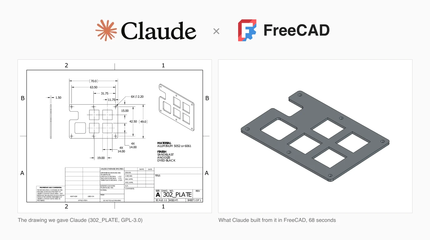
FreeCAD is the first program in this series we could actually run. SolidWorks and Revit need Windows and a licence, so in those articles we read the servers' code and tested files. FreeCAD is free and runs on a Mac, so this time we connected Claude to it, gave it a real engineering drawing to model, asked it for a TechDraw sheet of the original part, and then measured both results against the manufacturer's own model.
Our articles are still written by humans!
Get human written articles in your Google feed.

Is there an official connector?
No. FreeCAD is an open source project run by volunteers and the FreeCAD Project Association, not a company, and nobody has published a Claude connector for it. On 8 October 2026, Anthropic's connector directory listed Blender and Autodesk Fusion among its design tools and had no FreeCAD entry. So every route from Claude to FreeCAD goes through a community MCP server: a FreeCAD addon that accepts commands, plus a small program that Claude starts and that passes those commands on.
That sounds like a weakness, and for a firm that wants a vendor to call it is one. For everyone else it is less of a problem than with Revit or SolidWorks, because FreeCAD has a complete Python API. Anything you can do in the FreeCAD interface, a script can do, and Claude is good at writing those scripts.
The FreeCAD MCP servers
We cloned eight FreeCAD MCP servers and read their code. Star counts and dates are as of 8 October 2026. Only one is above 250 stars, and nothing else on GitHub came close.
FreeCAD MCP servers, from their source code on 8 October 2026
Two things stand out. Every one of them includes a tool that runs arbitrary Python inside FreeCAD, because that is the honest way to expose a program whose whole API is Python. And none of them has a TechDraw tool. TechDraw is FreeCAD's workbench for 2D drawing sheets, and in all eight codebases it appears only as a page type the screenshot tools refuse to capture, or as a name in a list. If you want a drawing, Claude has to write the TechDraw script itself, which is exactly what we tested below.
We used neka-nat/freecad-mcp. It has 17 tools: create, edit and delete objects, run code (live, in the background, or in a separate headless FreeCAD), take a screenshot of the 3D view, insert parts from the FreeCAD parts library, and run a CalculiX FEM analysis. It has no export tool either, so STEP, STL and PDF all go through the code tool too.
Wiring it up
This is what we did on an Apple silicon MacBook Air with FreeCAD 1.1.4 and Claude Code 2.1.294 running Claude Opus 5.5. Windows and Linux differ only in the folder in step 2.
- Install FreeCAD 1.1 (we used
brew install --cask freecad) and uv. The server needs Python 3.12 or later and uv fetches it for you. Do not install the server into FreeCAD's own Python, which the project's docs warn against. - Clone neka-nat/freecad-mcp and copy its
addon/FreeCADMCPfolder into~/Library/Application Support/FreeCAD/v1-1/Mod/. On Windows it is%APPDATA%\FreeCAD\v1-1\Mod\. If you are not sure, runprint(FreeCAD.getUserAppDataDir())in FreeCAD's Python console and addMod. - Restart FreeCAD, pick the MCP Addon workbench and click Start RPC Server. The status bar should show
127.0.0.1:9875. There is an Auto-Start Server option in the same menu if you do not want to click it every time; we used that. - For Claude Code, run
claude mcp add freecad -- uvx freecad-mcp. For Claude Desktop, add a server namedfreecadwith"command": "uvx"and"args": ["freecad-mcp"]undermcpServersinclaude_desktop_config.json, then quit and reopen it. - Ask Claude to list the FreeCAD tools, or to create an empty document. If it cannot connect, check that the RPC server is running in FreeCAD: the MCP server does nothing without it.
uvx, because apps launched from the Dock do not get your shell's PATH. Put the full path from which uvx in the command field instead.What we found in the code
In the Revit article the most popular server listened on the whole network with no password. FreeCAD's main server is the opposite, and it deserves saying so. We checked it two ways: in the code at commit 4751f95, and with lsof on our machine while it ran.
- It listens on 127.0.0.1 only. Other machines on your network cannot reach it. A Remote Connections option switches it to every interface, keeps an allow list that starts as 127.0.0.1, and warns you if no token is set. The docs suggest an SSH tunnel instead.
- It refuses web pages. Any request carrying a browser's Origin header, a non-XML body or a Host other than localhost is rejected, which closes the trick where a malicious website talks to a server on your own computer. It has tests for exactly that.
- A token is optional. Set one in FreeCAD and pass it in the
FREECAD_MCP_TOKENenvironment variable, which the docs prefer over a command line flag because flags show in the process list. It is compared in constant time. - The code tool cannot be switched off.
execute_codeis always available, and the project's own docs say it runs arbitrary Python inside FreeCAD with your user's permissions. That means files, network, everything your account can do.
The others are thinner. Only blwfish locks its socket so that other users on the machine cannot open it. contextform leaves its socket file in /tmp with no permission change we could find. spkane, bonninr and theosib have no authentication at all, although all of them stay on localhost.
execute_code, read what it is about to run when it touches anything outside the document, and work on a copy of files you care about.Test 1: model a part from a drawing
We reused the part from our SolidWorks test: the 302_PLATE from the open source fluxpad keyboard, a 1.5 mm aluminium plate published under GPL-3.0 with both a PDF drawing and the designer's STEP model. The drawing is a good test because it is real and imperfect. Its title block says “DIMENSIONS ARE IN INCHES”, which is wrong, and it gives no size at all for the slot, the large rounded cutout or any corner radius.
A fresh Claude in Claude Code, connected to FreeCAD and with no shell, got the drawing as a PNG and one instruction: model it as accurately as the drawing allows, export a STEP, and list every value you had to assume and anything you would ask the drafter. Then we loaded its STEP and the designer's STEP into FreeCAD, aligned them, and measured the difference.
Claude's FreeCAD model against the designer's STEP
That is a very good result. Everything that has a number on the drawing landed exactly on the original, to the thousandth of a millimetre. Where the drawing was silent, Claude worked out the scale of the image from the 70 mm width and measured, and its positions came within 0.2 mm. The two solids differ by 16.6 mm³, which is 0.5% of the part. Almost all of that is in the corners, where it guessed every radius smaller than the designer drew it.
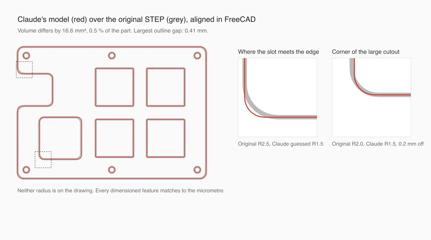
Its list of questions for the drafter was mostly what a checker would write: the inch note is a template leftover, the slot, cutout and radii are undimensioned, the vertical pitch of the squares is only implied, and Ø2.2 is an odd size that might be a tap drill. It also raised one false alarm: it said the isometric view seemed to be missing a hole. We checked the drawing, and all six are there. That is the same pattern as in the SolidWorks test, where the PDF reading produced one confident mistake among a lot of correct catches.
Test 2: make a TechDraw sheet
Then the other direction, which is what most people searching for this actually want from FreeCAD: a dimensioned drawing. A second fresh Claude got the designer's STEP and the request for an A3 ISO sheet with the main view, a side view for the thickness, and dimensions for the overall size, the thickness, and the mounting holes, exported as PDF and DXF.
It took 126 seconds and 14 calls to the code tool, one of which failed on a wrong attribute name and was fixed in the next call. Before placing anything it read the model's edges to find the holes, and afterwards it opened its own PDF three times and moved dimensions that overlapped. The sheet it produced is a real TechDraw drawing: FreeCAD's ISO 5457 template, a projection symbol, a 2:1 scale that suits a 70 mm part on A3, a filled title block, and nine dimensions, all of them correct.
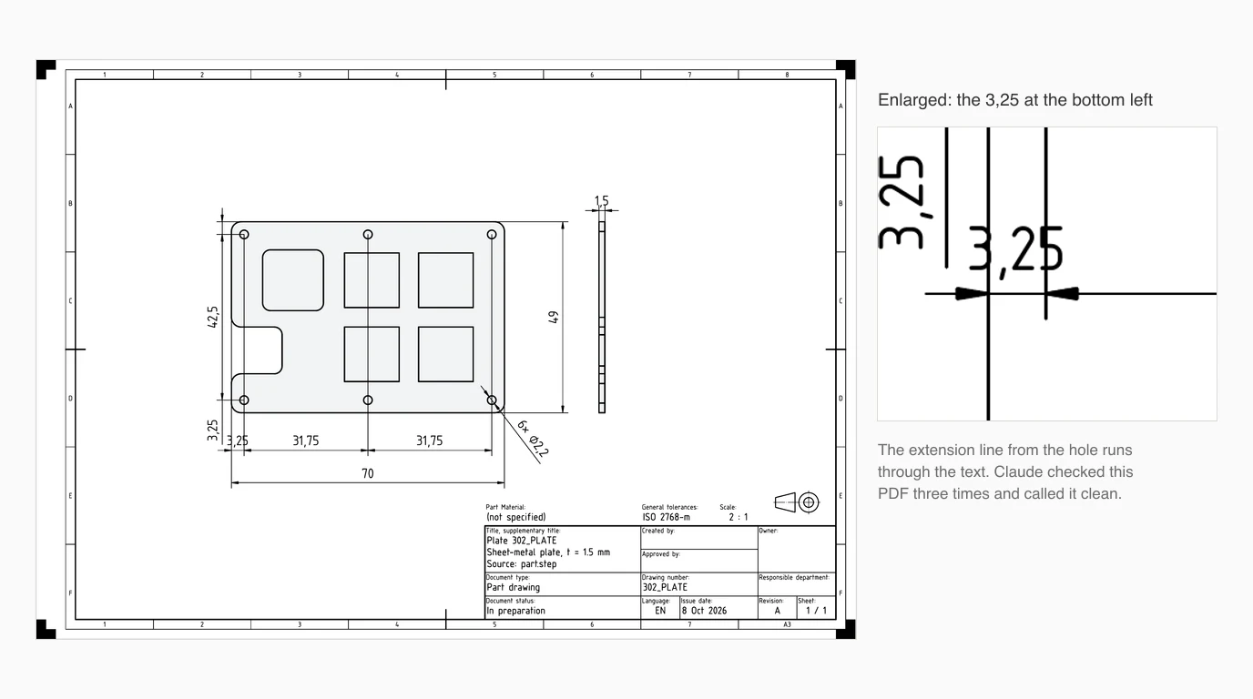
It is not a finished drawing, though, and some of what is wrong is what a person would catch in ten seconds:
- An extension line runs through a dimension. At the bottom left, the line from the first hole passes straight through “3,25”. Claude looked at the PDF after its last change and wrote “Layout is clean.”
- No centre marks. The holes have none, and the hole position lines are run right across the plate. Claude did mention the missing centre marks.
- Decimal commas. FreeCAD follows the system locale, so 31.75 came out as 31,75. Correct for much of Europe, wrong for a US shop.
- The part is drawn from the back. Compared with the designer's drawing, the slot and the rounded cutout have swapped top and bottom. For a plate cut straight through that changes nothing, and Claude said the choice of view was its own.
The DXF is the real trap
The PDF is fine to print. The DXF is where someone gets hurt, and it is not Claude's fault. FreeCAD's TechDraw export writes the page, not the part, so every line is at the sheet's 2:1 scale while the file declares millimetres. We read it back with ezdxf: the dimension labelled 70 measures 140. Send that DXF to a laser cutter and you get a plate twice the size. The hole note also came out as 6× ⌀2,2, because FreeCAD wrote the × and ⌀ characters as UTF-8 into a file that declares the Windows-1252 code page.
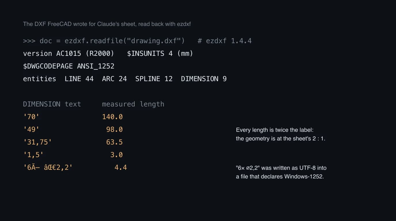
Claude noticed half of this. It reported that the DXF has no frame or title block, and it grepped the file for its dimension values. It did not notice the scale, because the numbers it searched for were the labels, which are right. If you need a DXF to cut from, export the part's outline at 1:1 from the 3D model, not the drawing page, and check the size before it goes anywhere. A DXF at the wrong scale is common enough that we have a whole guide to fixing it.
Have the STEP and need its views as a DXF at true size? Drop the model in your browser and get front, top and side views in real millimetres. Nothing is uploaded.
Open the orthographic projection toolWhat a FreeCAD file gives away
In the last two articles the native files leaked more than their owners would want: a Windows username and an OneDrive path in the SolidWorks part, login names and an office printer in the Revit model. So we opened the .FCStd that Claude saved. It is a zip with an XML description of the document, the geometry as BREP text, and a thumbnail.
It was clean. The FileName property, which holds the path while the file is open, is not written into it, and the CreatedBy, LastModifiedBy and Company fields were empty. What it does carry is the creation time with your time zone offset, and a PNG picture of the model. Those author fields fill in from FreeCAD's document preferences if you have set your name there, so check once before you send files out.
The FCStd format also makes FreeCAD the easiest program in this series for Claude to read without the program. The document XML and the geometry are plain text inside an ordinary zip, so a Claude with only a shell can open one and read every feature and value, which is not true of a SolidWorks or Revit file. We cover how that compares across formats in can Claude read CAD files.
What it is good at, and what it is not
- Good at: turning a dimensioned drawing into a solid, fast, and telling you what it had to guess.
- Good at: TechDraw scripting, which is tedious by hand: placing views, adding dimensions from edges, filling the title block, exporting.
- Good at: checking a drawing. Its list of questions for the drafter found every real gap in ours, along with one false alarm.
- Not good at: knowing what it did not see. It approved a layout with a crossed dimension and missed a DXF at double size. Somebody still has to look.
- Not good at: parametric models you can edit later. The model in our test was a plain solid built with Python, not a Part Design body with sketches and constraints. You can ask for that, but it is not what you get by default.
If you start from a photo or a sketch rather than a dimensioned drawing, Claude in FreeCAD has nothing to measure. That is the step TechDraw AI handles: it turns a photo of a part into a dimensioned drawing, which you can then give to Claude in FreeCAD as we did here. We have not run that hand-off end to end, so treat it as a route to try. Whether Claude can produce a drawing without any CAD program at all is a separate question, answered in can Claude make technical drawings. For other programs, see how to connect Claude to AutoCAD and our guide to CAD MCP servers.
FAQ
Frequently asked questions
Is there an official Claude connector for FreeCAD?
No. FreeCAD has no company behind it to ship one, and as of 8 October 2026 Anthropic's connector directory lists Blender and Autodesk Fusion but has no FreeCAD entry. You connect them with a community MCP server. The most used one is neka-nat/freecad-mcp, an MIT-licensed project with about 2,700 GitHub stars: a FreeCAD addon that Claude talks to through a small server started with uvx.
How do I connect Claude to FreeCAD?
Copy the FreeCADMCP folder from neka-nat/freecad-mcp into FreeCAD's Mod folder (on a Mac with FreeCAD 1.1 that is ~/Library/Application Support/FreeCAD/v1-1/Mod/), restart FreeCAD, switch to the MCP Addon workbench and click Start RPC Server. Then add a server called freecad with the command uvx and the argument freecad-mcp to Claude Desktop's config, or run claude mcp add freecad -- uvx freecad-mcp for Claude Code. You need uv installed, because the server needs Python 3.12 or later.
Can Claude model a part in FreeCAD from a drawing?
In our test, yes, and well. Given a PDF drawing of a 70 by 49 mm plate, Claude built it in FreeCAD in 68 seconds. Every dimensioned feature matched the original model exactly. For the features the drawing did not dimension it measured the picture and got within 0.2 mm on positions, but guessed corner radii 0.5 to 1 mm too small. The whole solid differed from the original by 0.5% of its volume. It also listed every value it had assumed, and raised one false alarm about a missing hole.
Can Claude make a TechDraw drawing in FreeCAD?
Yes, but none of the FreeCAD MCP servers we read has a TechDraw tool, so Claude writes TechDraw Python and runs it through the code tool. In our test it produced an A3 ISO sheet with two views, nine correct dimensions and a filled title block in about two minutes. It still needed a person: one extension line ran through a dimension, there were no centre marks, and the DXF that FreeCAD exported was at twice the real size.
Is the FreeCAD MCP server safe?
The neka-nat server is the most carefully built CAD server we have read in this series. Its addon listens only on 127.0.0.1 by default, refuses requests that come from a web browser, and supports an optional token. But it has an execute_code tool that runs any Python inside FreeCAD with your user's permissions, and there is no setting to switch that off. Treat it like giving Claude a Python prompt on your machine.
Does the FreeCAD MCP server work on a Mac?
Yes. We ran it on an Apple silicon MacBook with FreeCAD 1.1.4 from Homebrew, Claude Code and uvx. The addon goes in ~/Library/Application Support/FreeCAD/v1-1/Mod/. Unlike the SolidWorks and Revit servers, nothing here needs Windows.
Sources
- neka-nat/freecad-mcp on GitHub (commit 4751f95)
- neka-nat/freecad-mcp: installation guide
- neka-nat/freecad-mcp: configuration and security
- freecad-mcp on PyPI
- spkane/freecad-addon-robust-mcp-server
- blwfish/freecad-mcp
- bonninr/freecad_mcp
- contextform/freecad-mcp
- Anthropic: Claude connectors directory
- FreeCAD Wiki: TechDraw Workbench
- FreeCAD Wiki: Licence (logo and trademark)
- sssata/fluxpad: the open source keypad whose plate we tested (GPL-3.0)
- ezdxf: Python library used to read the exported DXF
- Model Context Protocol: official specification and docs