
The model was right. The print looks right. The pin will not go in the hole. Every person who has printed a functional part has had this afternoon, and the fix is almost never a better printer. It is knowing what your process actually holds, designing the gap on purpose, and writing the two or three dimensions that matter somewhere a person can check them.
Our articles are still written by humans!
Get human written articles in your Google feed.
The short answer
If you want the numbers and nothing else: on a healthy desktop FDM machine, expect about ±0.5% of the dimension with a floor of roughly ±0.5 mm, leave 0.3 to 0.4 mm of total gap between parts that should slide together, oversize any hole you care about by 0.2 to 0.4 mm, and print critical bores with their axis vertical. On SLA resin you can roughly halve the gaps. On SLS or MJF nylon, keep at least 0.3 to 0.5 mm so the unfused powder can get out.
Everything below is why those numbers are what they are, and how to write them down so the part comes back right the first time.
Why a print is never the size you drew
A printed part is a stack of decisions the slicer made on your behalf, and each one contributes a small error in a predictable direction. They are not random. Once you know which is which, most of them can be designed around instead of chased.
- The first layer is squashed. The nozzle presses the first layer into the plate so it sticks, and the plastic spreads outward. The base of the part ends up a few tenths oversize with a visible lip, which everyone calls elephant foot. It is why a part sits proud in a pocket that fits perfectly two millimetres up.
- Extrusion has a width, and it goes somewhere. The slicer places bead centrelines, not surfaces. Any mismatch between the assumed and the actual bead width biases every wall in the same direction, which is why a badly calibrated printer misses every dimension consistently rather than randomly.
- Curves are polygons. A circle is approximated by straight segments and the extruded plastic sits inside the ideal curve, so holes come out small and outside cylinders come out close to nominal. This is the single biggest surprise for people coming from machining.
- Material shrinks as it cools or cures. Shrinkage is a property of the polymer, not the printer, and it acts on the whole part, so a long dimension loses more absolute size than a short one.
- Z is quantised, XY is not. A height is built from whole layers, so a 10.05 mm feature at 0.2 mm layers becomes 10.0 mm. XY can land anywhere. Two dimensions on the same part genuinely have different achievable resolutions.
What each process actually holds
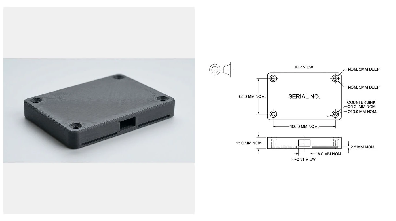
Tolerance specs for additive processes are almost always quoted as a percentage with a lower limit, and the lower limit is the part people miss. On a 20 mm feature a 0.5 percent spec works out at 0.1 mm, but the floor of 0.5 mm is bigger, so the floor wins. The percentage only starts to matter on parts over about 100 mm.
Typical dimensional accuracy by process. Treat as a starting expectation, not a guarantee.
Clearances that make parts fit
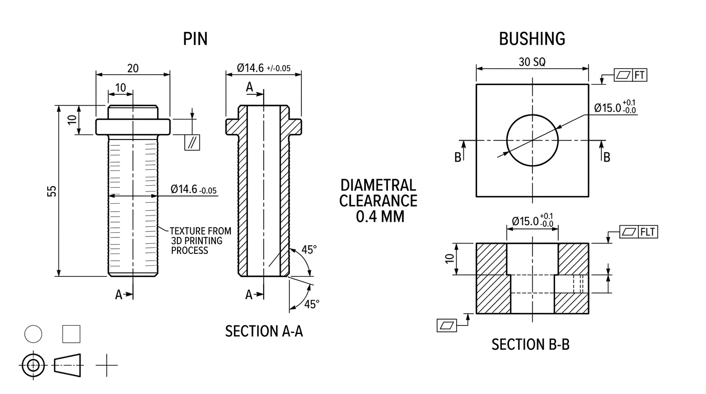
A clearance is the gap you deliberately model between two surfaces that have to meet. It is not slop and it is not a fudge factor. It is the allowance that absorbs everything in the section above, and it is the single most useful number in this whole article.
Total diametral or face-to-face gap to model in, by fit and process
Three things about that table decide whether it works for you. It is total gap, so on a pin in a hole you can take it all out of the hole or split it between both parts, but you only get to spend it once. It is per interface, so a lid that fits into a recess on all four sides needs the value on each side, not once across the width. And it assumes the parts come off the same machine in the same material, because mixing a resin part with an FDM part means the looser process sets the gap.
Holes, pins and threads
Round features are where additive processes are least like the CAD model, so they deserve their own rules.
Holes come out small
On FDM a nominal 5 mm hole commonly measures 4.6 to 4.8 mm. The polygonal approximation and the inward bulge of the bead both take material out of the bore. Your options, in order of reliability:
- Drill or ream after printing. Model the hole undersize on purpose, then open it with a drill. This is the only route that gets you anywhere near a machined fit, and it takes seconds.
- Oversize the model by 0.2 to 0.4 mm on diameter, measured once on your own machine and then reused.
- Use the slicer compensation if it has one, since most modern slicers expose a hole or XY size compensation value that fixes every hole at once.
Horizontal holes go oval
A hole printed with its axis parallel to the plate has an unsupported top, so the last layers sag into the bore and the section becomes an egg rather than a circle. Design the bore axis vertical wherever you can. Where you cannot, either make the hole a teardrop or a hexagon so there is no unsupported horizontal span, or accept it and drill.
Do not print small threads
Below about M6, printed threads on FDM are a false economy: the profile is coarser than the pitch and they strip. Use a heat-set brass insert, a captive nut pocket, or cut a thread into the printed plastic with a tap. M8 and above can work printed if the load is light and the axis is vertical. On resin, printed threads down to M4 are usable because the feature fidelity is genuinely finer.
Orientation decides which dimension is good
Build orientation is usually discussed as a strength and support question. It is equally a tolerance question, and unlike strength it is invisible once the part is in your hand.
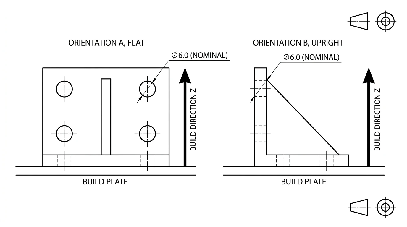
- XY beats Z for fine dimensional control on FDM, because Z is built in whole layers.
- Vertical bores stay round, horizontal bores sag.
- Supported faces are rough and oversize where the support was removed, so any surface that has to seat flat against another part should not be a support interface.
- Tall thin parts move more, because warp accumulates with height and every layer is another chance to shift.
Because orientation changes which dimension is accurate, it is a specification, not a preference. If a part has one bore that must be round, the drawing has to say which way up it is built. A bureau will otherwise orient for cost and packing density, and they are right to, because you did not tell them.
Shrinkage, warp and the first layer
Shrinkage is a material property and it applies to the whole part, so the absolute error grows with size. Warp is what happens when different regions shrink at different times, and it shows up as lifted corners and a part that is no longer flat.
Typical linear shrinkage and warp behaviour by material
Two practical consequences. First, a design that fits in PLA may not fit in ABS, so the material belongs in the specification alongside the dimensions. Second, elephant foot is a separate effect from shrinkage and needs a separate fix: a small chamfer of 0.4 to 0.6 mm on the bottom edge, or the elephant foot compensation setting in your slicer. Chamfer the model rather than the settings if the part will be printed by somebody else.
Measure your own printer, not a chart
Everything above is a starting expectation. Your machine, your material and your profile have their own numbers, and finding them takes one print and ten minutes with a caliper.
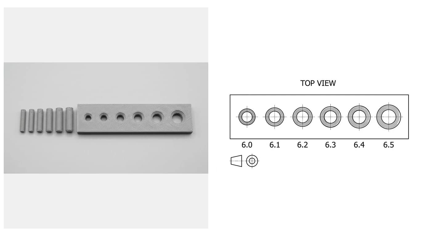
- Print a clearance gauge. A bar with a row of holes stepping up in 0.1 mm increments, plus matching pins, tells you in one go which gap slides and which one binds on your setup.
- Print a calibration cube and measure all three axes. You are not looking for perfection, you are looking for whether the error is the same in X and Y and different in Z.
- Measure the same part from three prints. If the three agree with each other but not with the model, you have an offset you can compensate. If they disagree with each other, fix the machine before you touch the model.
- Write the numbers down next to the material, the nozzle and the layer height, because they do not transfer between profiles.
Putting it on a drawing
An STL carries geometry and nothing else. No tolerances, no material, no orientation, no note about which bore matters. That is fine when you print it yourself an hour after modelling it, and it is the root cause of most bad outcomes any other time: a part reprinted next year, a job sent to a bureau, a design handed to a colleague, a file sold to a customer.
A drawing that goes with a printed part should carry:
- A general tolerance note in one place, covering every dimension that is not called out individually. Something like plus or minus 0.5 mm is honest for FDM and saves you tolerancing forty features.
- Two or three critical dimensions with their own tighter values, boxed or otherwise marked so they are visibly different from the rest.
- Process, material and layer height, because the tolerances above are meaningless without them.
- Build orientation, at least for the axis that matters, drawn as an arrow.
- Post-processing callouts: ream this bore to size, tap this hole M4, install a heat-set insert here, do not sand this face.
- Which faces are cosmetic, so the supports go somewhere you do not care about.
The discipline is the same one any manufacturing ready drawing follows, and if the tolerance notation itself is unfamiliar, reading tolerances on a drawing covers what the symbols mean before you start writing them.
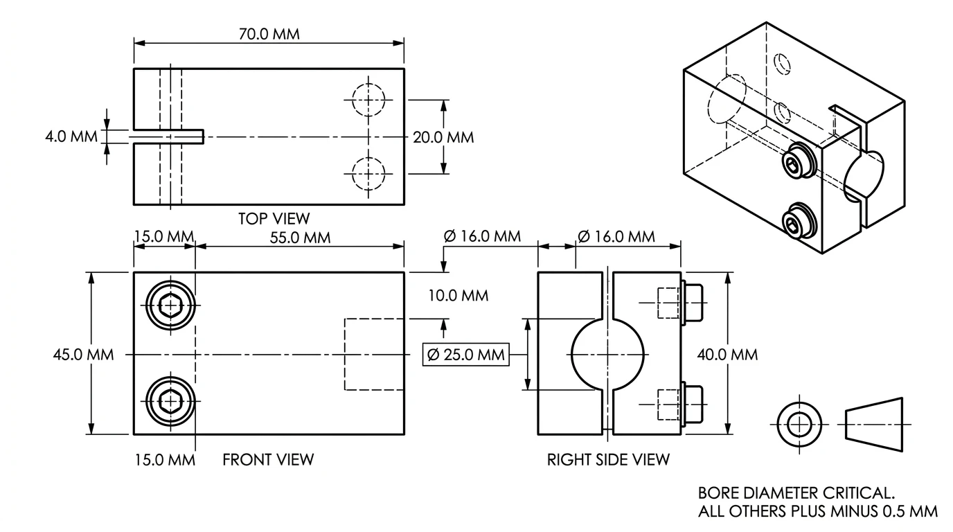
What a print service needs from you
Sending work out changes the economics of every decision above, because you are no longer the person who finds out the hole is tight. A bureau quotes from what you send, prints what you specified, and inspects against whatever you gave them to inspect against, which is often nothing.
What to send, and what happens when you do not
A STEP file is worth sending alongside the STL whenever you have one, because it carries real geometry rather than a triangle mesh, and it lets the bureau adjust or repair a feature without guessing. The difference between the two is the same one that separates STEP from DXF: one describes surfaces, the other describes an approximation of them.
The pre-print checklist
- Every mating gap is modelled, at the value for the fit you actually want, on one side or split across both.
- Critical bores are oversized or marked to be reamed.
- Bore axes are vertical where roundness matters, or teardropped where they cannot be.
- Bottom edges are chamfered 0.4 to 0.6 mm against elephant foot.
- Threads under M6 are inserts, nuts or tapped, not printed.
- Material chosen with shrinkage in mind, and the design checked against that material rather than the one you prototyped in.
- Seating faces are not support interfaces.
- A general tolerance note plus two or three called-out dimensions exist on a drawing, not just in your head.
- Build orientation is specified if any dimension depends on it.
- Your own printer numbers are measured, not inherited from an article like this one.
That last point is the one that matters most. The tables above will get a first print close, and a clearance gauge will get the second one right. Once you know your machine, write the numbers on a drawing so the knowledge survives the part, and let TechDraw AI turn the part you already printed into that drawing rather than remodelling it from scratch.
Frequently asked questions
What tolerance can a 3D printer hold?
A well-tuned desktop FDM printer holds roughly plus or minus 0.5 percent of the dimension with a floor of about plus or minus 0.5 mm, so small features are limited by the 0.5 mm floor rather than the percentage. Resin SLA is tighter, around plus or minus 0.5 percent with a floor near 0.1 to 0.15 mm. SLS and MJF nylon sit around plus or minus 0.3 percent with a floor near 0.3 mm. Industrial machines beat all of these, and any specific printer beats or misses its own spec depending on calibration.
How much clearance should I leave between 3D printed parts?
On FDM, start at 0.2 mm total gap for a tight press fit, 0.3 to 0.4 mm for a part that should slide, and 0.5 mm or more for anything that has to rotate or was printed in place. On SLA you can halve those. On SLS you need 0.3 to 0.5 mm minimum so unfused powder can escape. These are gaps between the two surfaces, so if you split the allowance across both parts, each gets half.
Why is my 3D print the wrong size?
Usually one of four things. The first layer is squashed into the plate and spreads, which makes the base a few tenths oversize, known as elephant foot. The material shrank as it cooled, which varies by polymer and is worst on ABS and nylon. Extrusion width or resin exposure is off, which biases every wall in the same direction. Or the model was measured in one axis and the error lives in another, since Z accuracy on FDM is quantised by layer height while XY is not.
Do 3D printed holes come out undersize?
Almost always on FDM, and by more than people expect. The slicer approximates a circle as a polygon and the extruded plastic bulges inward on the curve, so a nominal 5 mm hole often measures 4.6 to 4.8 mm. Holes printed with their axis horizontal are worse again because the top of the hole sags into an ellipse. The reliable fixes are to oversize the modelled hole by two to four tenths, print the axis vertical where you can, or drill and ream the hole after printing.
What is the difference between accuracy and precision on a printer?
Accuracy is how close a printed dimension is to the number you drew. Precision is how close ten copies of the same part are to each other. Printers are often far more precise than they are accurate, which is good news: a consistent offset can be measured once and compensated in your model or slicer, whereas random scatter cannot be designed around and has to be fixed mechanically.
Should I put tolerances on a drawing for a 3D printed part?
Yes, but only on the dimensions that matter. Put a general tolerance note in one place covering everything, then call out the two or three fits, bores and mating faces that actually control function with their own tighter values. Tolerancing every dimension tightly on a printed part is the fastest way to have a bureau either refuse the job or quote it as if it were machined.
Can I get a drawing of a part I have already printed?
Yes, and it is a common need when the CAD is lost, the part came from a downloaded model, or you want to document what you actually shipped. Photograph the printed part, anchor the scale with one caliper measurement, and generate a dimensioned drawing you can check against the print. That is what TechDraw AI does for the 3D printing vertical, and it is the same workflow used to reverse engineer any physical part.
Sources
- ISO/ASTM 52900:2021 Additive manufacturing, General principles, Fundamentals and vocabulary
- ISO 286-1:2010 Geometrical product specifications (GPS), ISO code system for tolerances on linear sizes, Part 1: Basis of tolerances, deviations and fits
- ISO 286-2:2010 Tables of standard tolerance classes and limit deviations for holes and shafts
- Single View Metrology in the Wild (ECCV 2020): absolute scale cannot be recovered from one image without a known reference