Laser Cutting Cost Calculator
Cut length, pierces and sheet area measured from your own DXF, priced with your own rates.
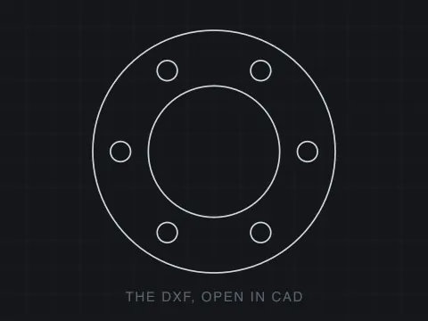
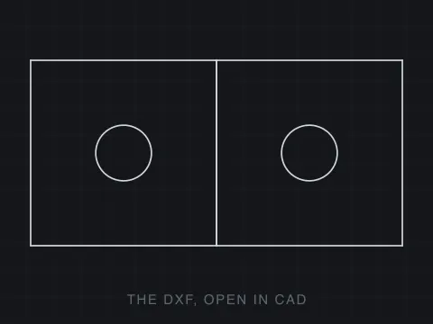
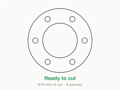
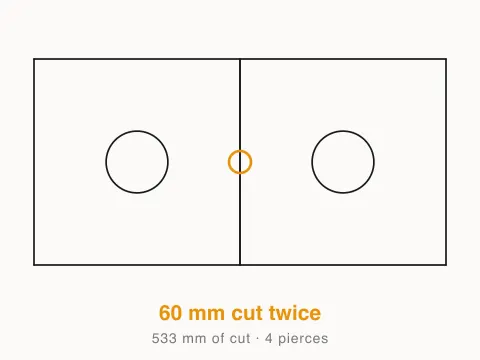
Drop a file here. It never leaves your browser.
No sign-up · no upload · no file size limit · priced with your own rates
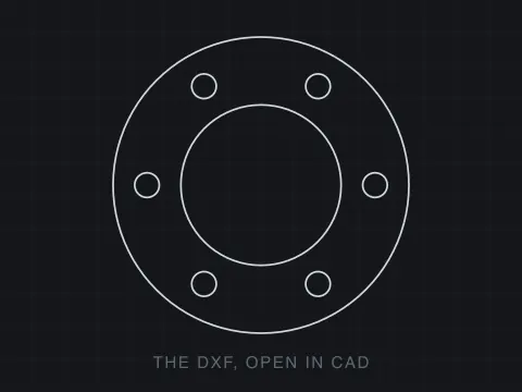
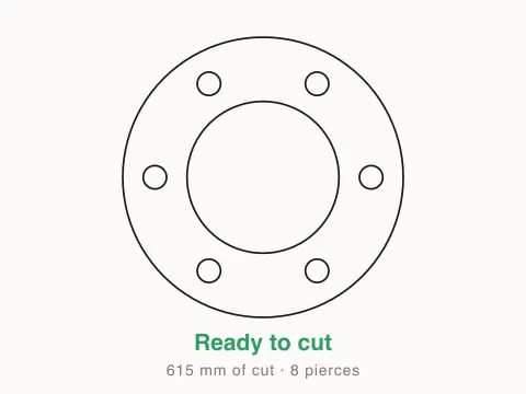
How to price a job from the file
Drop your file
A DXF, DWG or SVG. It is read in your browser and never uploaded, so nothing under NDA has to leave your machine.
Switch off what is not cut
Dimensions, hatches and the title block usually live on their own layers. Turning those off takes them out of every number below, not just out of the picture.
Type your rates
Feed rate, pierce time, machine rate and material price. The cut length, the pierces and the areas are already measured from the file; the rates turn them into money.
What is measured and what is guessed
Most cutting calculators ask you to type a cut length you do not have, or work one out from the bounding box, which is wrong by whatever fraction of the rectangle is actually holes. This one reads the geometry. Every arc and circle is flattened, every entity is welded into a contour, and the millimetres are added up along the path the beam will follow. Where a line was drawn twice, the doubled stretch is counted once, because the machine only travels it once even though a naive total charges for both.
Pierces are counted the same honest way: one per contour, because every closed profile and every open run has to be started. On a part with forty holes that is forty pierces plus the outline, and at a waterjet’s pierce time it can be most of the cycle. Areas are nesting-aware — a hole subtracts, an island inside that hole adds again — so the part area is the material you get back and the sheet area is the rectangle you had to buy.
One number here is a guess and it is marked as one. Rapid travel between contours depends on the order your CAM decides to cut in, which is not in the drawing and cannot be recovered from it, so the estimate charges half a bounding-box diagonal per pierce. That is deliberately pessimistic: a good nest beats it easily. If your quotes need to be tighter than that, the cut length and the pierce count on this page are the two numbers to take into your own spreadsheet.
About formats
DXF (Drawing Exchange Format) is a CAD data file format developed by Autodesk, first released in December 1982 with AutoCAD 1.0 to enable interoperability between AutoCAD and other programs. The format exists in two variants: ASCII DXF, a human readable text file organised into sections (HEADER, TABLES, BLOCKS, ENTITIES, OBJECTS), and binary DXF for faster parsing. Each geometric entity, including lines, arcs, circles, polylines, splines, text, dimensions and 3D solids, is described by group codes paired with values that specify coordinates and properties. DXF versions evolve alongside AutoCAD releases, adding support for new features with each edition. One major advantage is universal CAD compatibility, since DXF is supported by virtually every CAD, CAM and engineering application across all platforms, which makes it the most widely accepted exchange format for technical drawings. The ASCII variant is another strength, because drawings can be inspected, debugged and generated programmatically with text tools or scripts. DXF serves as a critical bridge that lets architects, engineers and manufacturers share precise drawings regardless of which software each party uses, and it remains the standard for cross platform CAD data exchange.
- Developer:
- Autodesk
- Initial release:
- December 1982
Frequently asked questions
How does it work out the cut length?
By measuring it. Every entity is flattened into segments, arcs and circles included, then welded into contours and added up in millimetres. Where a line was drawn twice the doubled stretch is counted once, because the beam only has to travel it once even though a naive total counts it twice. That is usually the difference between this and a quote worked out from the bounding box.
Is the estimate accurate?
The measurements are exact and the arithmetic on top of them is only as good as the rates you type. Cut length, pierce count, part area and sheet area come straight off your geometry. Cutting time is that length over your feed rate, which is real for a constant feed and optimistic on a part full of tight corners where the machine cannot hold it. The one genuine guess is rapid travel between contours, because the order the parts are cut in is decided by your CAM and is not in the drawing; it charges half a bounding-box diagonal per pierce, which is deliberately pessimistic.
Does it work for plasma and waterjet?
Yes. Nothing in the measurement is laser-specific: cut length, pierce count and sheet area are the same numbers whatever is doing the cutting. Change the feed rate and the pierce dwell to your machine's and the estimate follows. Waterjet pierce times are much longer than laser ones and plasma feed rates much higher, and both are just numbers in the boxes.
Why is the material cost based on the bounding box?
Because that is what a single part actually consumes when it is cut on its own: you buy the rectangle it has to come out of, not the shape you get back. The part area with holes subtracted is shown beside it, and the ratio between them is the yield. Nesting several parts together is what closes that gap, and nesting is a different job that depends on how many of each you are making.
Is my file uploaded anywhere?
No. The DXF is opened by code running in your browser tab and never sent to a server, so nothing is stored, logged or scanned. You can disconnect from the internet once the page has loaded and it keeps working. That also means a drawing under NDA can go through it without a conversation with anyone's legal team.
Is this calculator free?
Yes, and free in the way that matters: no account to see the result, no account to download the report, no watermark and no file size limit. There is no paid tier of this tool to upsell you to.
What can it open?
DXF of any version, DWG back to R14, and SVG. DWG is a closed format read here by a reverse-engineered parser, so a file AutoCAD saved yesterday occasionally reads better if you save it as DXF first. SVG is included because a lot of cut files arrive from Illustrator and Inkscape rather than from CAD.
My rectangle is drawn as four separate lines. Will it say the contour is open?
No, and getting that right is most of what this tool is. Before anything is measured the entities are welded: endpoints within 0.01 mm of each other are treated as the same point, and the chains are walked until they close or run out of neighbours. A rectangle drawn as four lines, drawn in any order, with any of them drawn backwards, comes back as one closed contour. Only after that does an open contour mean something is actually missing.
Why does it separate a 0.2 mm gap from a 30 mm one?
Because you do something different about each. Ends a fraction of a millimetre apart are a drafting slip — a snap that missed — and most CAM will bridge them on import, so you want to know before it does it silently. An end thirty millimetres from its partner means an entity is missing and no amount of bridging is going to invent it. Same defect class, two different afternoons.
What counts as a line cut twice?
Any stretch where two segments lie on the same infinite line and their spans overlap, not just identical entities. That catches the copy-paste, the two parts sharing an edge that both of them drew, and the half-overlap where one line runs past the end of another. The beam follows both: wider kerf, a burnt edge, and machine time on the invoice.
Does it check whether the part is any good?
No, and nothing that reads only a file could. It checks that the geometry is cuttable — closed, unambiguous, not doubled, in known units. Whether the part is the right size, whether a 2 mm web will survive in 6 mm steel, whether the material is right: none of that is in the DXF. It is a check on the file, not an opinion on the design.